Week 9 Machining with Planer Challenge
Expilicit Dynamic analysis of Machining with a Planar.
Aim: Expilicit Dynamic analysis of Machining with a Planar by taking Steel 1006 material for workpiece and veloctiy of cutter for case 1 as 20000 mm/s and case 2 as 15000 mm/s.
Steps followed:
1) Material selection:
Material of workpiece & cutter reamins same for case 1 & 2 as mentioned below.
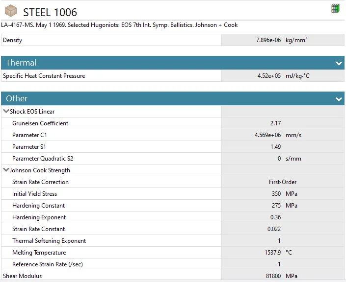
For workpiece Steel 1006 material is choosen with material specification as shown in the image below:
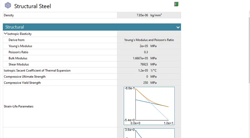
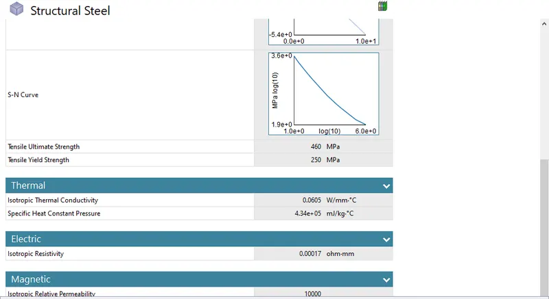
For cutter Structural steel is choosen with material specifications as shown in the image below:
2)Geometry:
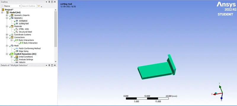
Geometry for Cutter-Workpiece assembly is imported from the CAD files with assembly as shown in the image below:
For both Case 1 & Case 2 geomerty are similar.
3) Models:
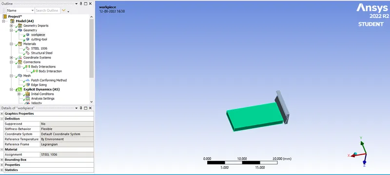
Workpiece is assigned with Steel 1006 as shown in the image below:
4) Connections:
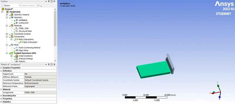
For both case 1 & 2 Bonded type contact between cutter & workpiece is deleted only Body interactions remains as shown in the image below:
5) Meshing:
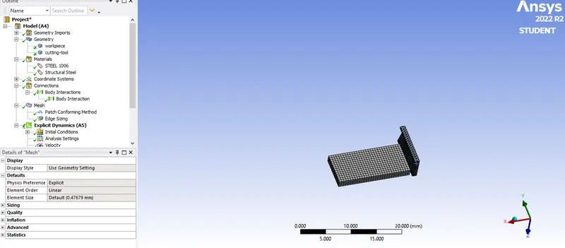
Tetrahedron meshing is applied by Body selecting the Cutter as it has complex geometry as shown in the image below:
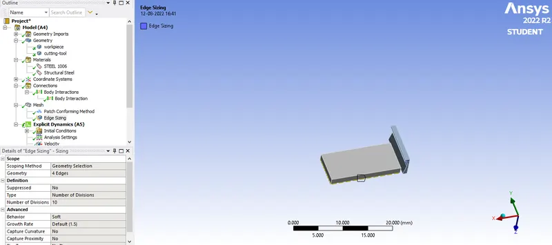
Edge sizing is applied by selecting the small edge of Workpiece with Type as Number of Divisions which is applied as 10 like shown in the image below:
6) Boundary canditions:
a)Analysis setting:
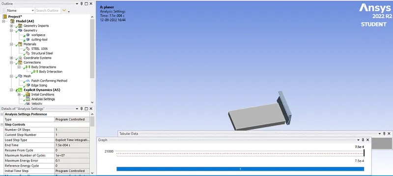
For both Case1 & 2 Number of steps taken as 1 with End Time is inputed as 7.5 e-04 s and Maximum number of cycles as 1E+07,Maximum Energy Error as 0.1. Intial time step,Minimum Time step & Maximum time step as Programme Controlled.
b)Fixed support:
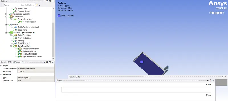
Fixed support for case 1 & 2 is applied to the workpiece with similar settings.
A fixed support is applied to the workpiece by selecting it's one of the faces as shown in the imge below:
c)Velocity:
Case 1:
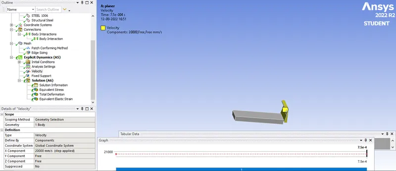
Velocity of 20000 mm/s is applied with the help of Body selection to the cutter along X axis by keeping the Y & Z axis at constant of 0 as shown in the image below:
Case 2:
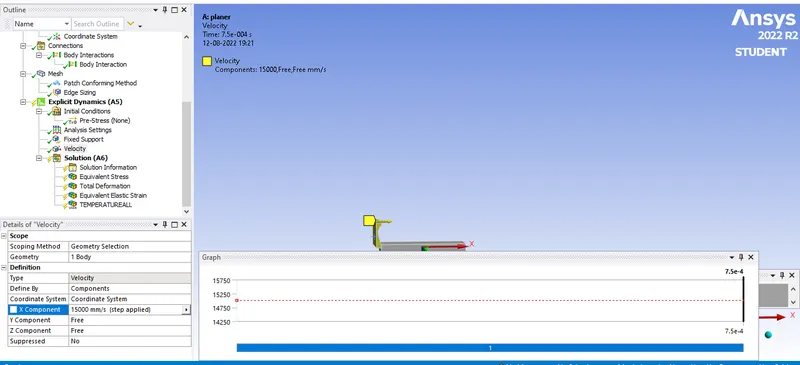
Velocity of15000 mm/s is applied with the help of Body selection to the cutter along X axis by keeping the Y & Z axis at constant of 0 as shown in the image below:
Results:
Case 1:
Equivalent Stress:
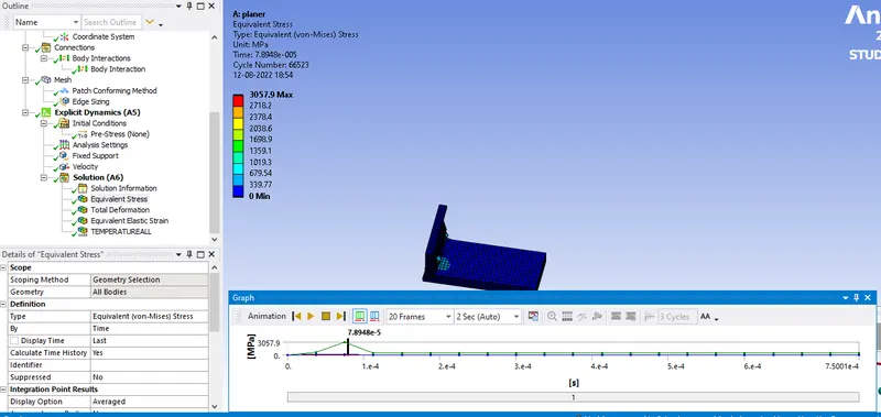
Equivalent Stress vs Time graph:
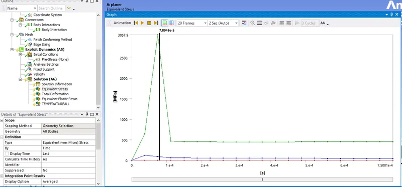
Maximum Equivalent stress:3057.9MPa.
Total Deformation:
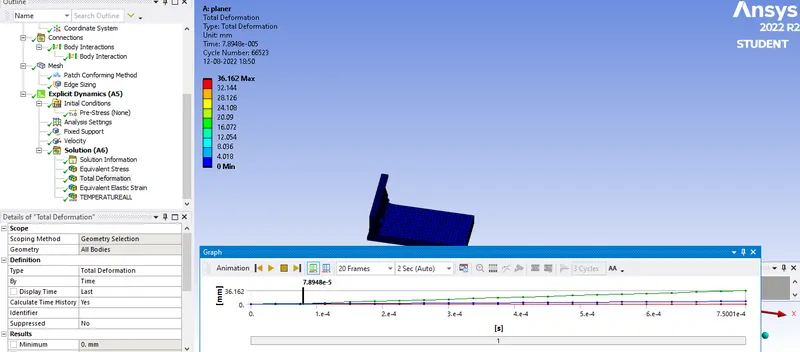
Total Deformation vs Time graph:
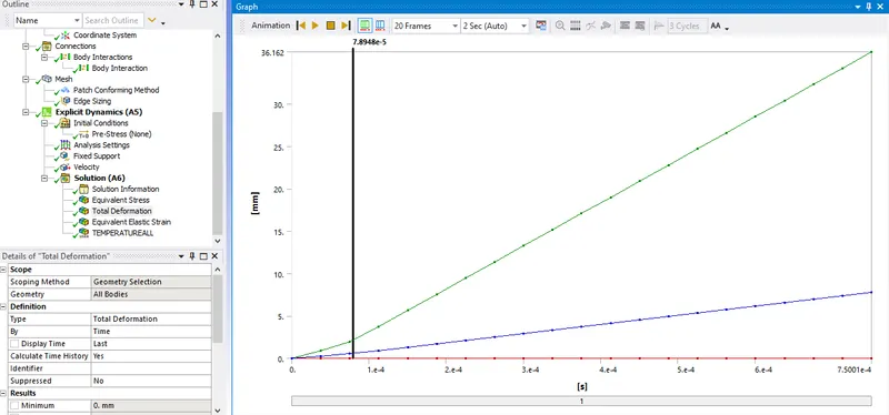
Maximum Total Deformation:36.162 mm
Temprature of Workpiece:
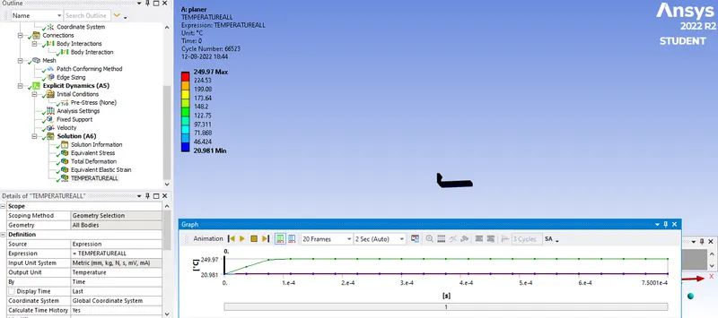
Temprature vs Time graph:
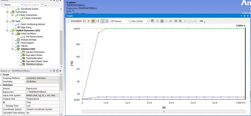
Maximum Temprature of workpiece: 249.97 C
Case 2:
Equivalent Stress:
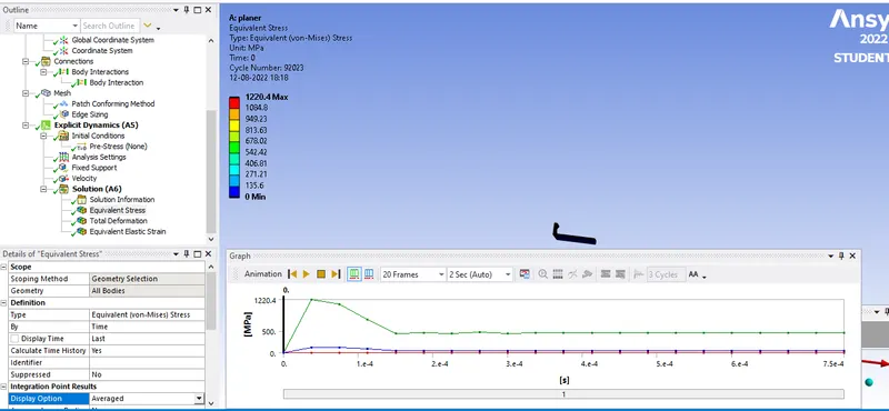
Equivalent Stress vs Time graph:
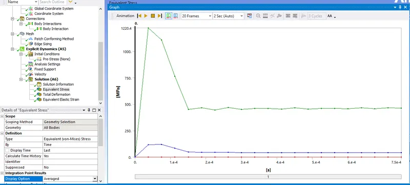
Maximum Equivalent stress:1220.4 MPa.
Total Deformation:
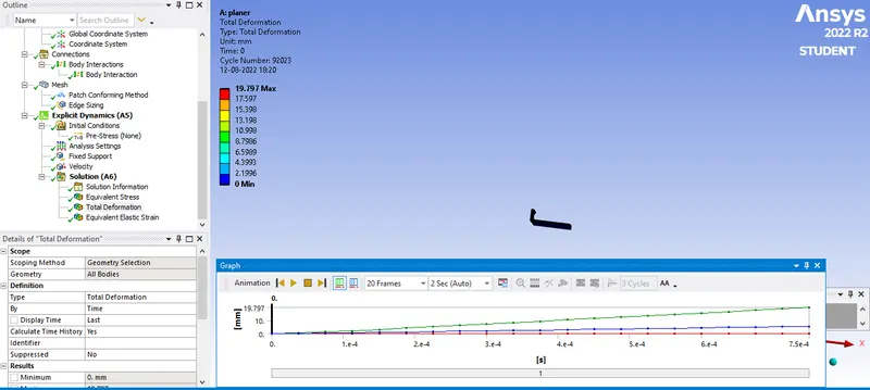
Total Deformation vs Time graph:
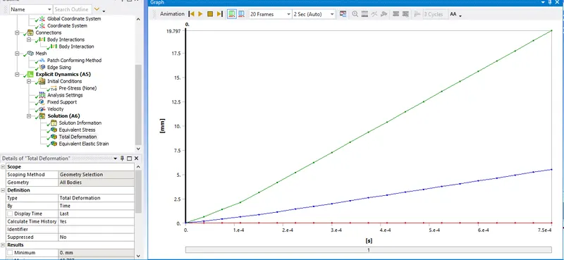
Maximum Total Deformation:19.797 mm
Temprature of Workpiece:
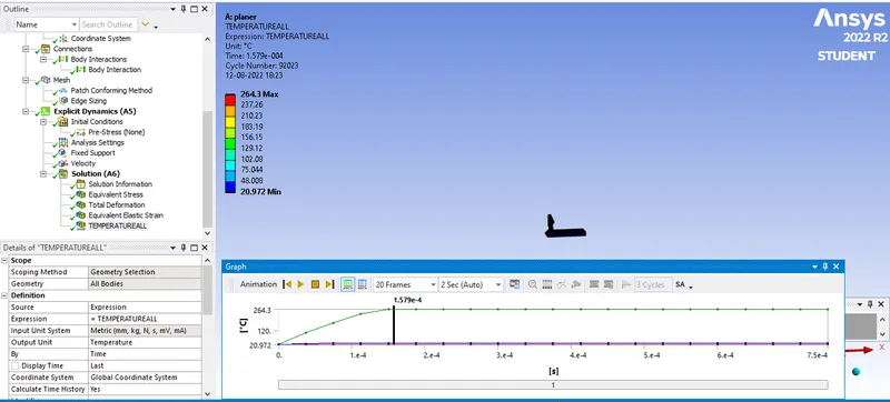
Temprature vs Time graph:
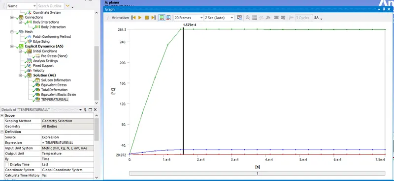
Maximum Temprature of workpiece: 264.3 C.
Comparison of Maximum equivalent stress, maximum total deformation & temprature of workpiece for case 1 & 2:
| Case | Maximum Equivalent Stress(MPa) | Maximum Total Deformation(mm) | Maximum Temprature(C) |
| 1 | 3057.9 | 36.162 | 264.3 |
| 2 | 1220.4 | 19.797 | 249.97 |
Conclusion:
- Maximum total deformation in case 1 than in case 2 because of high velocity of cutter.
- Maxiimum equivalent stress occurs in case 1 compared to case 2 again reason being high velocity of cutter.
- Maximum temprature in case 1 is higher than in case 2 because of high rate of chip removal by cutter due to its high velocity.