Week 9 Machining with Planer Challenge
Aim: The objective of this project is to run a simulation and compare results for a machining operation at two different velocities for the tool.
Model Setup: A CAD model has been imported into Explicit dynamics workbench. The tool was set to be rigid as we are not interested in the tool damage. Steel was assigned to the workpiece. The default interaction has been left to be frictionless.
Mesh: A mesh size was given to the edges of the workpiece as shown in image 1.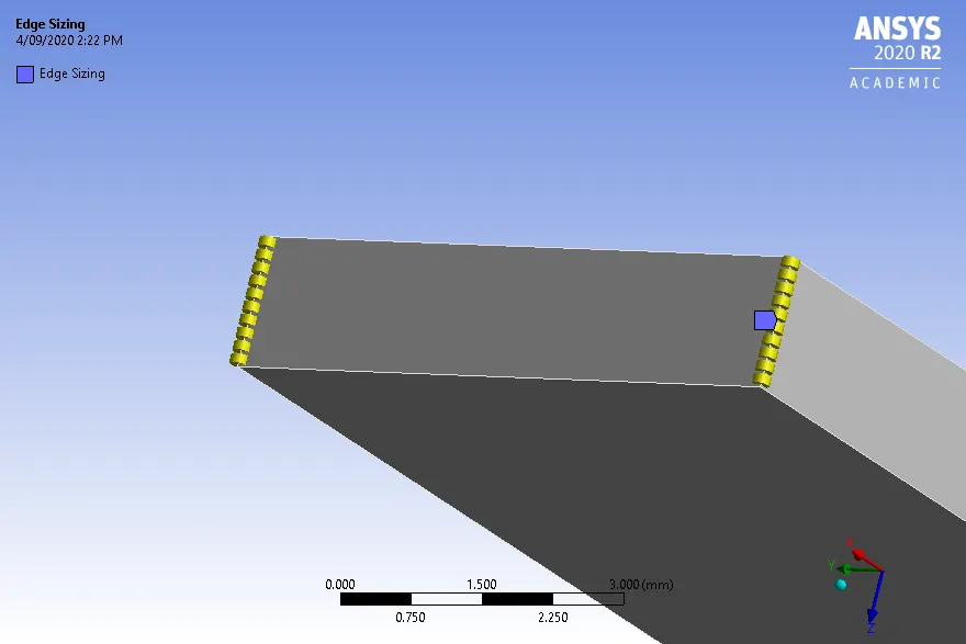
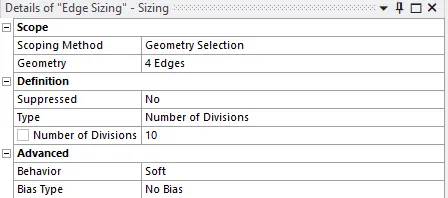
Image 1: Edge Sizing
A tetrahedron method was defined to the tool. These mesh settings gave resultant mesh as detailed in image 2.
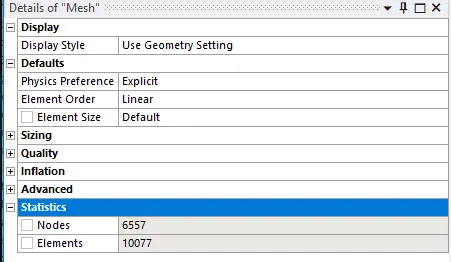
Image 2: Mesh details.
Analysis Settings: The analysis was set to end at 0.001seconds. The lower end of the workpiece was fixed as shown in image 3. The tool was set to move in negative x-direction with a velocity of 20000mm/s (case 1) and 15000 mm/s (case 2).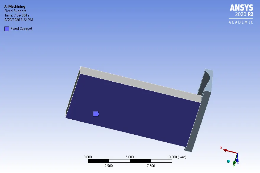
Image 3: Fixed support
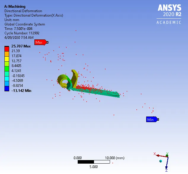
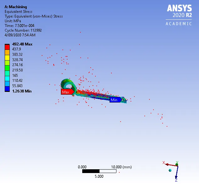
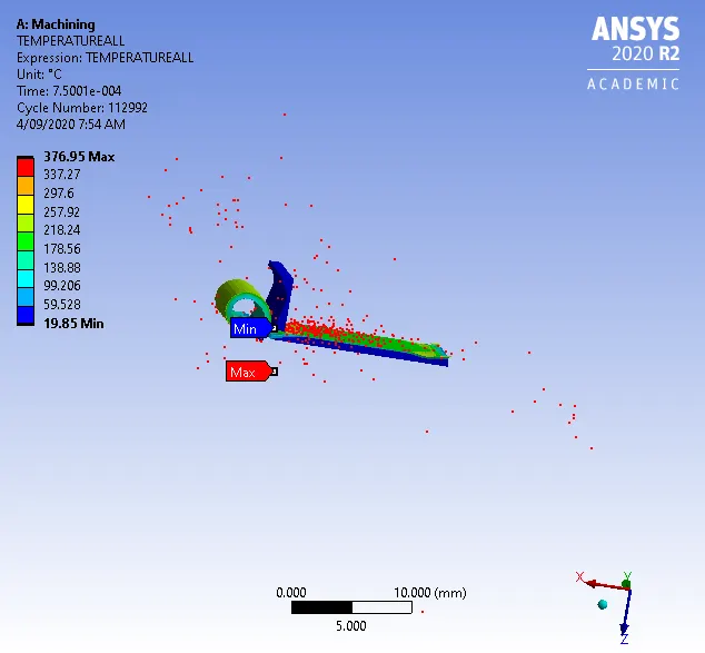
Results and Conclusions: The results for case 1 simulation are given below:
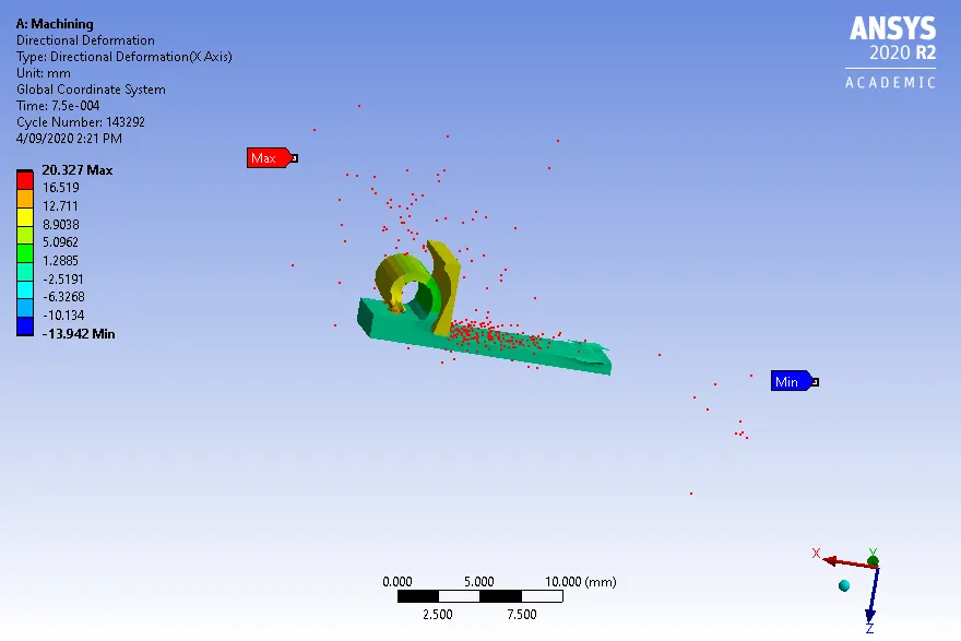
The results for case 2 simulation are given below:
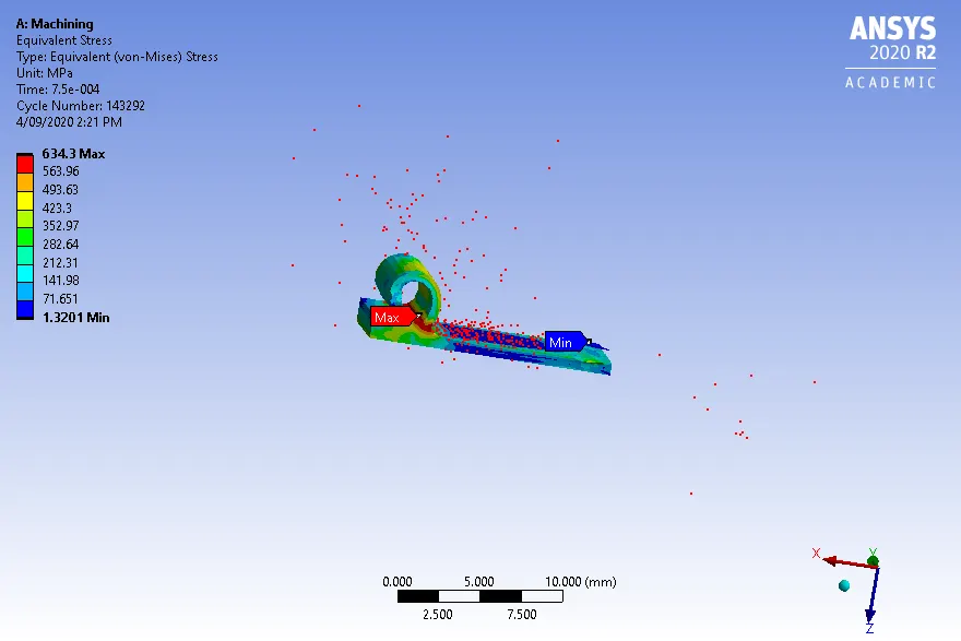
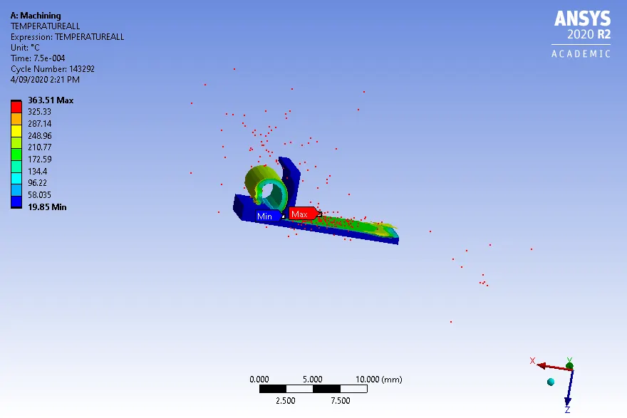
The results are tabulated below
| Deformation(mm) | Stress(MPa) | Temperature(Degree C) | |
| Case 1 |
Max 25.707 Min -13.142 |
492.48 1.2638 |
376.95 19.85 |
| Case 2 |
Max 20.327 Min -13.942 |
634.3 1.3201 |
363.51 19.85 |
From the above results, we can conclude that decreasing the velocity increases the smoothness of the workpiece. Deformation decreases as velocity decreases. Stresses increase and temperature decrease with an increase in velocity.