Week 9 - FVM Literature Review
Objective: -
To study and understand
1. The difference between FDM and FVM.
2. Interpolation scheme in FVM.
3. Flux limiters in FVM.
Description: -
There are total 4 numerical methods:
1. Finite Element Method (FEM)
2. Boundary Element Method (BEM)
3. Finite Volume Method (FVM)
4. Finite Difference Method (FDM)
FDM
Boundary conditions are needed to truncate the computational domain. They represent communication with the surrounding world, which is the part that we do not want included on our simulation. With the finite-difference method, we may easily run into problems handling boundaries for the purpose of defining boundary conditions.
The finite-difference method is the most direct approach to discretizing based upon the differential form of the PDE to be solved. We consider a point in space where we take the continuum representation of the equations and replace it with a set of discrete equations, called finite-difference equations.
The finite-difference method is typically defined on a regular/structured grid (i.e. the computational domain is usually divided into hexahedral cells (the grid), and the solution will be obtained at each nodal point.) and this fact can be used for very efficient solution methods. Regular grids are useful for very large scale simulations on supercomputers.
The method is therefore not usually used for irregular CAD geometries, but more often for rectangular or block-shaped models.
Examples include Formula 1 car computational-fluid-dynamic (CFD) simulations and space-shuttle CFD simulations. The finite difference method is more difficult to use for handeling material discontinuities. In addition, it does not lend itself for local grid refinement or anything similar to "adaptive mesh refinement". This may be needed to resolve local rapid variations in solutions such as around a corner of a complex shape, as described earlier.
But, if we can fit the simulation in a rectangular or box-shaped geometry using a regular grid, efficient implementations are much easier than finite-volume method.
If we can overcome the boundary-condition problem on curved boundaries, the method gives very efficient and high-quality results.
A finite volume method (FVM) discretization is based upon an integral form of the PDE to be solved (e.g. conservation of mass, momentum, or energy) and can handle discontinuities in solutions. The PDE is written in a form which can be solved for a given finite volume (or cell). The computational domain is discretized into finite volumes and then for every volume the governing equations are solved. The resulting system of equations usually involves fluxes of the conserved variable, and thus the calculation of fluxes is very important in FVM.
The finite-volume method's strength is that it only needs to do flux evaluation for the cell boundaries. This also holds for nonlinear problems, which makes it extra powerful robust handling of (nonlinear) conservation laws appearing in transport problems.
The local accuracy of the finite-volume method, such as close to a corner of interest, can be increased by refining the mesh around that corner. However, the functions that approximate the solution when using the finite-volume method cannot be easily made of higher order. This is a disadvantage of the finite-volume method compared to the finite-difference method.
The basic advantage of this method over FDM is it does not require the use of structured grids, and the effort to convert the given mesh in to structured numerical grid internally is completely avoided. As with FDM, the resulting approximate solution is a discrete, but the variables are typically placed at cell centers rather than at nodal points. This is not always true, as there are also face-centered finite volume methods. In any case, the values of field variables at non-storage locations (e.g. vertices) are obtained using interpolation.
FVM can guarantee the local and global conservation of the system.
Steps for FVM descritization:
1. We will write the required governing equation in its integral form.
2. Apply Gauss Divergence Theoram.
3. We obtain discretised form which can be solved using a computer('Flux Term').
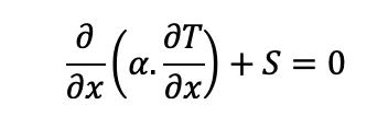
Consider a steady state heat conduction equation with a source term (heat generation source):
where
S is the source term
𝜶 is thermal diffusivity
∂T/∂x is temperature gradient along x direction.
The above governing equation is valid at every point in the domain, meaning it is valid for the entire control volume.
If we consider a small control volume (dv) and it is multiplied with the governing equation and integrated for entire volume then that should also be equal to zero i.e. the integral form of governing equation.
Taking the conservation equation validated at single point and if it is validated at single point then it is validated at entire volume and in this entire volume the properties are conserved.
Multiplying the equation by 'dv' and integrating it, we obtain,
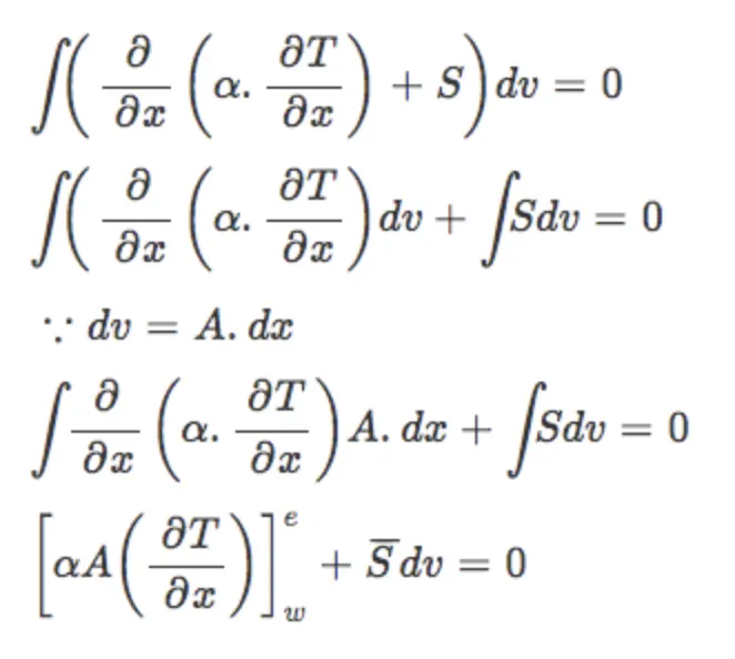
 is the average value of source term (S) which when multiplied by dv will be equal to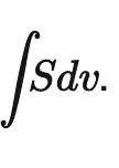
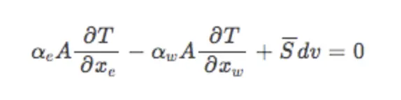
If we assume 𝜶 as a constant and not as a function of temperature,
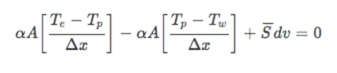
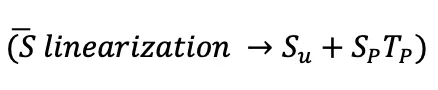
The source term which is to be added in a cell, if it is a function of temperature we have to linearize it. If we consider 𝜶 as a function of temperature we have to linearize it as well.
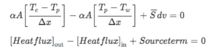
The amount of heat that is removed from a particular box is conserved.
Different schemes are used to solve this:
- Interpolation scheme
In the finite volume formulation, evaluation of surface and volume intergrals sometimes requires the values of unknown variables at locations other than the computational nodes of the control volume. These values are obtained by employing certain interpolation schemes.
As an example let us consider the simple case of steady state one dimensional convection and diffusion.
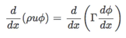
where
𝝓 is our solution variable (scalar)
ρ is the density
u is the velocity
 is the diffusion coefficient.
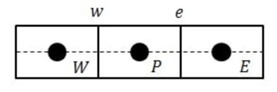
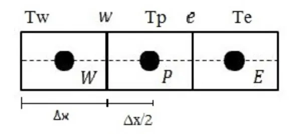
The above figure represents the three neighbouring control volumes, which we are going to use for deriving the discretization equation.
Integration of the governing diiferential equation over the control volume around grid point P yields:

Evaluation of LHS of the above equation requires values of 𝝓 over faces e and w. These values are estimated by employing certain interpolation schemes.
Some interpolation schemes used in CFD are as follows:
1. Upwind interpolation scheme.
2. Linear interpolation scheme.
3. Quadratic upwind interpolation for convective kinematics (QUICK) scheme.
4. Hybrid scheme.
5. Total variation diminishing (TVD) scheme.
a. Upwind interpolation scheme
This scheme takes into account the direction of fluid flow and based on it the value of solution variable at the face is approximated by its value at the upstream computational node. For example, if the fluid is moving from west to east then,
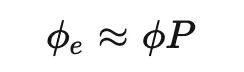
if the flow is moving from east to west, then
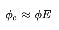
- Flux limiters
While calculating the variable gradients they tend to toggle and are not bounded to a particular value and keep jumping. This occurs due to discontinuity, having a flux limiter will help to bound the gradient value giving a stable solution.
Numerical approximation using higher order spatial discretization schemes results in better accuracy but exhibits spurious oscillations near discontinuities such as shocks. On the other hand, lower order spatial discretization schemes remain stable near discontinuities but dampen out the distributions due to their dissipative nature. Hence to capture discontinuities, high resolution schemes are required which are highly accurate and stable throughout the domain.
Flux limiters operate functionally as a switch and tune the numerical fluxes obtained from a lower order scheme and higher order scheme such that near the discontinuity lower order (stable) scheme is employed and away from it higher order (accurate) scheme is employed.
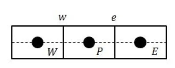
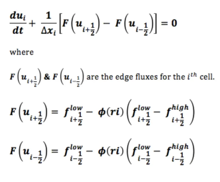
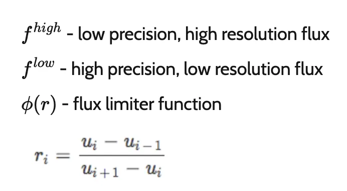
Suppose a flux at face e is calculated using a high resolution scheme, Le represents flux at e calculated using low order scheme and He represents flux at e calculated using high order scheme.

Flux limiter function depends upon the smoothness parameter r which is defined as:
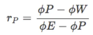
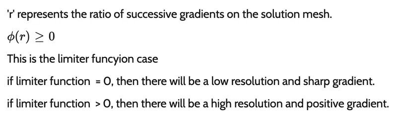
The flux limiter function is constrained to be greater than or equal to zero. It assumes a value of 0 near discontinuities and a value of 1 away from them. Hence it switches between higher order scheme and lower order scheme for numerical representation of flux, thereby keeping the scheme stable and accurate throughout.
Also the flux limiter are also reffered to as slope limiters because they both have the same mathematical form, and both have the effect of limiting the solution gradient near shocks or discontinuities. In general, ther term flux limiter is used when the limiter acts on system fluxes and slope limiter is used when the limiter acts on system states (like pressure, velocity etc.)
Considr 1D-semi discrete scheme,