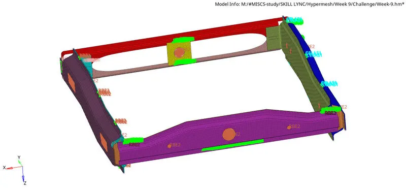
Week 9-Creation of 1D Connectors Challenge
Objective:
To mesh the given ggeometry by satisfying the required quality criteria and to create connectors and attach various parts of the model.
Procedure:
Import model:
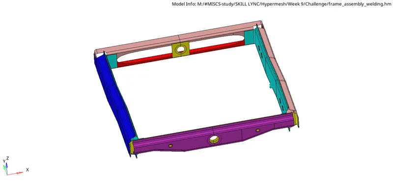
- To import the cad model, goto New model > Import geometry and select the file to import.
Geometry cleanup:
- To start with, goto Geometry > autocleanup and enter the target element size as 5 in the edit criteria & edit parameters menu.
- Select the surface to be cleaned up and click on autocleanup.
- The autocleanup function generates washers automatically.
- Manual cleanup can be done by using the quick edit > toggle edge, quick edit > split surf, quick edit > washer split, quick edit > unsplit surf, quick edit > project point & quick edit > replace point.
- Remove all the unnecessary points by using the quick edit > add/remove point.
- As only shell meshing is to be performed, Solids are not necessary. Hence, Goto Delete > Solids and delete all the solids present in the model.
Quality Criteria File settings:
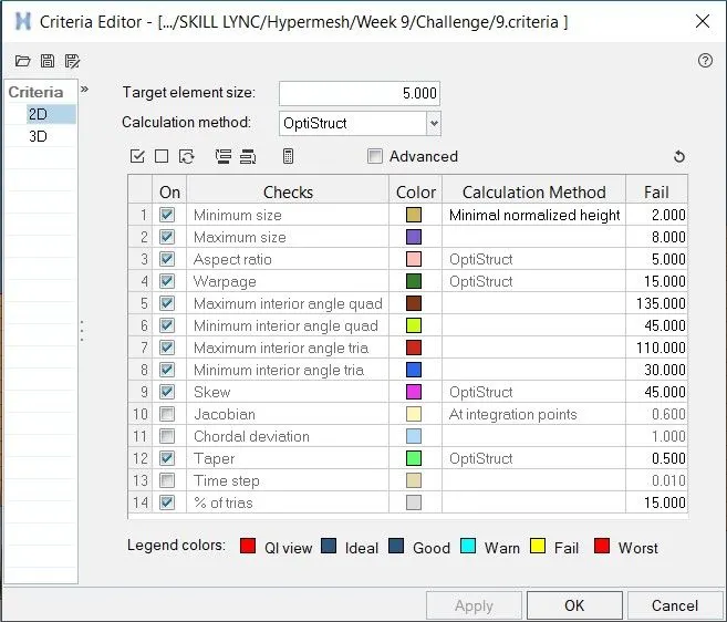
To define the required Quality criteria, goto Preferences > Criteria File settings > Criteria Editor and enter all the required criteria.
Mesh generation:
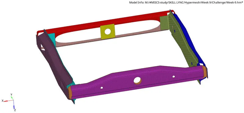
- Next in order to mesh the surfaces, goto 2D > Automesh and enter the mesh element size = 5.
- Choose the surface to be meshed and click on the mesh button.
- To check the element quality, goto Tools > Check elements or press F10 or goto 2D > elem cleanup.
- The failed elements can be corrected by using the elem cleanup or the elem quality index > cleanup tools or using any of the manual operations.
- To check if there are any duplicate elements present, press F10 > duplicates. If duplicates are present, then click on Save failed and goto Delete > elements > retrieve and delete the excess elements.
- Goto Tools > edges, select the surfaces and click on find edges to check if any of the elements are disconnected from the neighbouring elements. To rectify this, click on equivalance or goto > 2D replace and join the nodes manually.
- To check the normals of the elements, goto Tools > normals > elements > displayed elements and click on display. To invert the normals, click on reverse. If any of the elements are not aligned to the neighbouring element's normals, click on adjust or then select those elements and click on reverse.
- To check if the surfaces and the elements overlap each other correctly, goto Mesh > Check > Elements > comparison and choose the target & sources. Enter the tolerance value and click on Run.
Reflect:
To reflect the symmetrical portion of the components, goto Tools > reflect > elements, select the required elements and choose the nodes N1, N2, N3 & B or select the axis by which the elements have to be reflected upon. Click on reflect.
Connectors creation:
1. Right_Rail_2 & Front_truss_1:- Seam-Quad(angled+capped+L)
- Goto 1D > Connectors > Seam >node path, select the nodes and the components to which the connection has to be assigned.
- Enable retain nodes option and then choose the type as 'Seam-Quad(angled+capped+L)', enter the tolerance and spacing values.

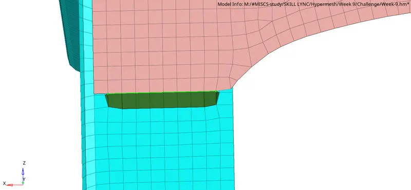
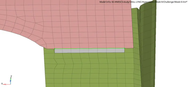
2. Left_Rail_2 & Front_truss_1:- Quad elements
- Goto 1D > Connectors > Seam >node path, select the nodes and the components to which the connection has to be assigned.
- Enable retain nodes option and then choose the type as 'Quad elements', enter the tolerance and spacing values.

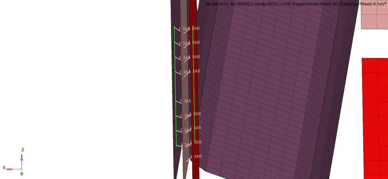
3. Front_truss_2, Front_truss_1 & Right_Rail_1:- Spot weld with 2 Layers and 5 mm Diameter
- Goto 1D > Connectors > Spot >node path, select the nodes and the components to which the connection has to be assigned.
- Enable retain nodes option and then choose the type as 'weld', enter the tolerance and spacing values.

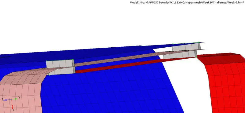
4. Front_truss_2, Front_truss_1 & Left_Rail_1:- Hexa (Adhesive)
- Goto 1D > Connectors > Seam >node path, select the nodes and the components to which the connection has to be assigned.
- Enable retain nodes option and then choose the type as 'Hexa (Adhesive)', enter the tolerance and spacing values.
- Enter the width of the adhesive and the number of coats & strips.

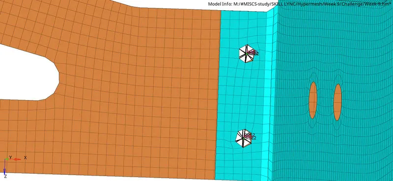
5. Rear_truss_2 & Right_Rail_2:- Bolt Connector
- Goto 1D > Connectors > Bolt >nodes, select the node and the components to which the connection has to be assigned.
- Enable retain nodes option and then choose the type as 'Bolt (general)' and enter the tolerance values.
- Select the 'create hole, if none' option since there are no holes on the geometry.

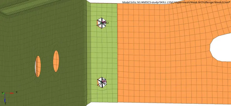
6. Rear_truss_2 & Left_Rail_2:- Bolt Connector
- Goto 1D > Connectors > Bolt >nodes, select the node and the components to which the connection has to be assigned.
- Enable retain nodes option and then choose the type as 'Bolt (general)' and enter the tolerance values.
- Select the 'create hole, if none' option since there are no holes on the geometry.
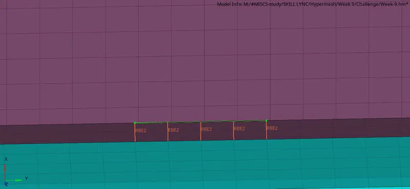
7. Right_Rail_1 & Right_Rail_2:- Spot-weld with Rigid Elements
- Goto 1D > Connectors > Spot >node path, select the nodes and the components to which the connection has to be assigned.
- Enable retain nodes option and then choose the type as 'rigid', enter the tolerance and spacing values.

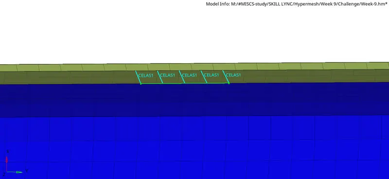
8. Left_Rail_1 & Left_Rail_2:- Spot-weld with Spring Elements
- Goto 1D > Connectors > Spot >node path, select the nodes and the components to which the connection has to be assigned.
- Enable retain nodes option and then choose the type as 'weld', enter the tolerance and spacing values.

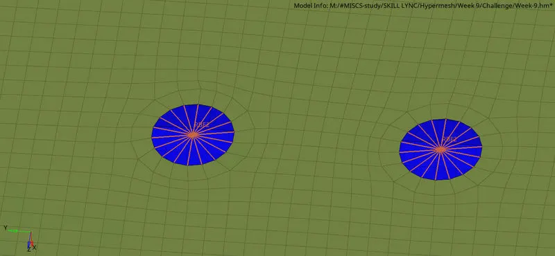
9. RBE2 elements:
- Goto 1D > Rigids > Calculate nodes > loops, select the nodes to which the connection has to be assigned.
- Choose the type as 'RBE2'.

Result:
Thus, the given ggeometry is meshed by satisfying the required quality criteria and the various parts of the model are attached by assigning the suitable connectors.