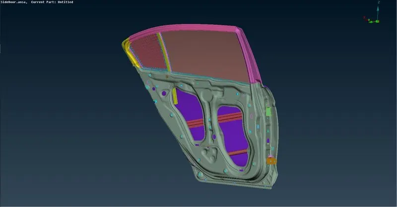
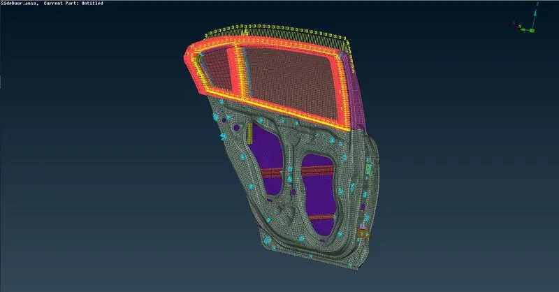
Week 6 - Creating connection for Rear door
Aim:
To Create and Apply different PIDs for different components and to deploy suitable connections for the given Rear door FE model.
Procedure:
- Import Geometry: Go to File > Open > Select file to import.
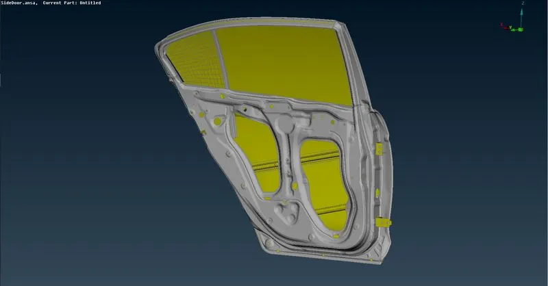
- Set PID: Select the different parts of the rear door model and assign separate PIDs for each of the parts.
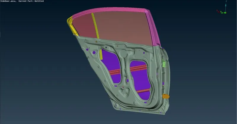
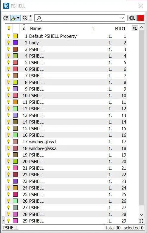
- Assign Connections: In this model I have used the following types of connections.
- RBE2 cluster
- Goto Nastran deck > RBE2 > Many Nodes and select the nodes where RBE2 connection needs to be established.
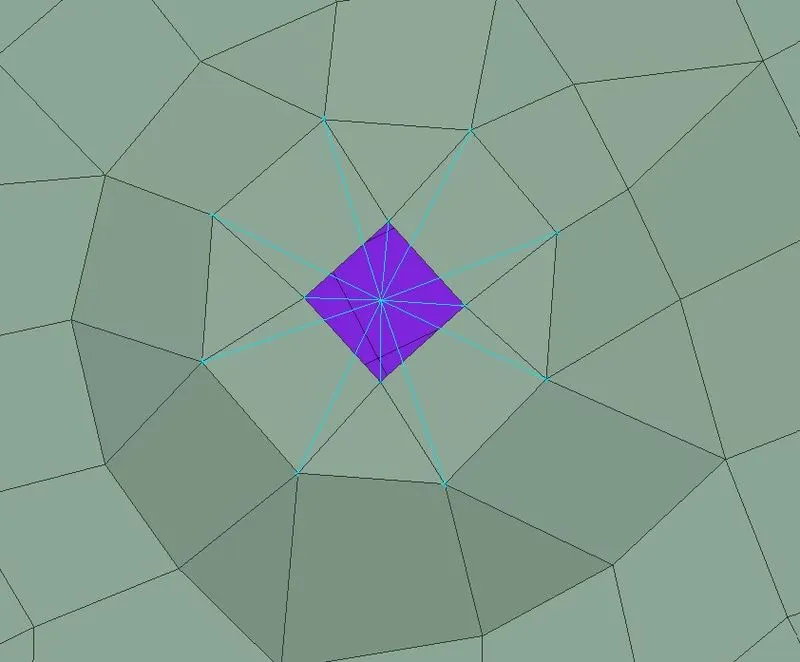
- Click Next > Next > Finish.
- RBE2 with 2 Node RBE2
- Goto Nastran deck > RBE2 > Two Nodes and select the nodes where 2 node RBE2 connection needs to be established.
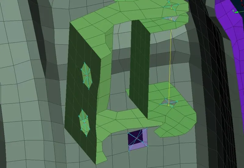
- Then, Middle mouse Click > Enter name > Enter the degree of freedom and click on OK.
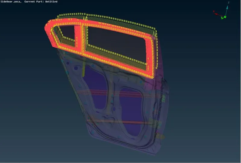
- RBE3-CBUSH-RBE3
- Select the edges where the CBUSH connection needs to be established and convert those edges into curves.
- Then use Convert option to convert the curves into Seam line.
- Open connection manager and select the seam line and choose the parts to be connected (in this case the Window glass and the body Shell part).
- Select RBE3-CBUSH-RBE3 as the FE rep type.
- Enter the search distance, PBUSH ID and pinflags.
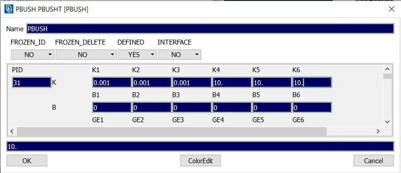
- Select Keep all branches and then click on Apply and then Realize to deploy the CBUSH connection.
- Spot Weld
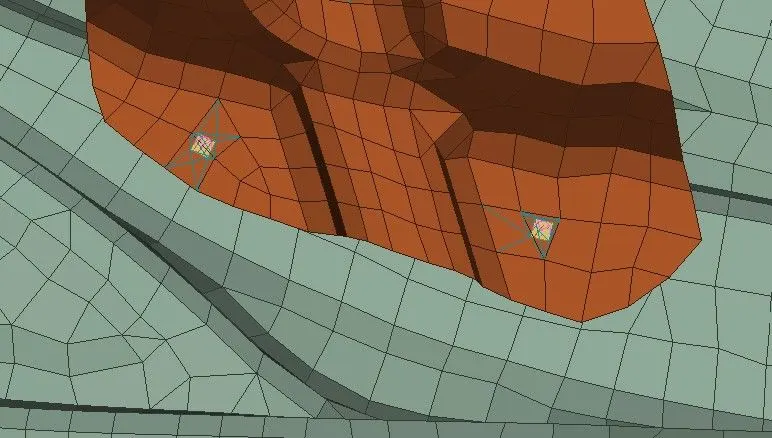
- Goto Topo deck > Points > On COG > select the entities to which the COG point is to be created.
- Click Convert > 3D points > Spotweld point.
- Open Connecion manager > select the spotweld point > select the different parts to be connected with each other > Select RBE3-HEXA-RBE3 as the FE rep type.
- Enter the search distance and then enter the pinflag value as 123456.
- Then choose a PSOLID by pressing Shift+?
- After entering all the necessary values, click on Apply and then Realize in order to deploy the spot weld connection.
- Seam Weld
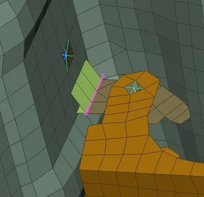
- Select the edges where seam weld connections need to be established and convert it into curves using the Feature2curve option.
- Then Goto Convert > Curves > Seam line to convert the curve into Seam line
- Open connection manager and select the seam line and middle click on the mouse. Then select P1 and P2.
- Select Y-JOINT-SHELL in the FE rep type drop down menu.
- Enter all the required parameters and click on Apply and then Realize to deploy the connection.
- RBE2 cluster
Learning Outcomes:
- Gained knowledge on the different types of connections available and the various approaches to assign the connections.
Conclusion:
Thus, the appropriate onnections were assigned to the given Rear door FE model.