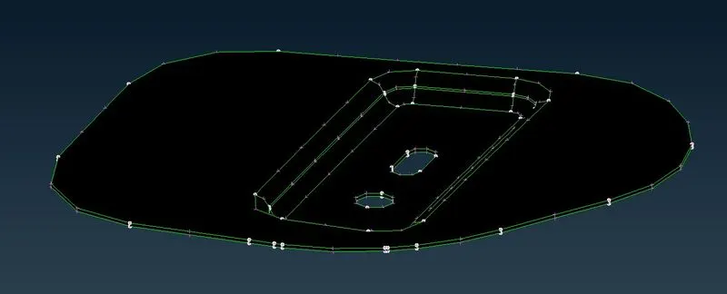
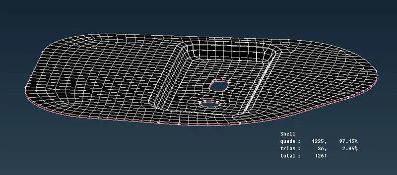
Car Hood Mid-surfacing and 2D Meshing
Aim:
To generate mid surface for all the components in the given Hood model after verifying the geometrical errors and to do 2D mesh on the generated mid surface that satisfies the given Quality criteria.
Procedure:
Since all the components in the model have thickness less than 5mm, 2D meshing can be done.
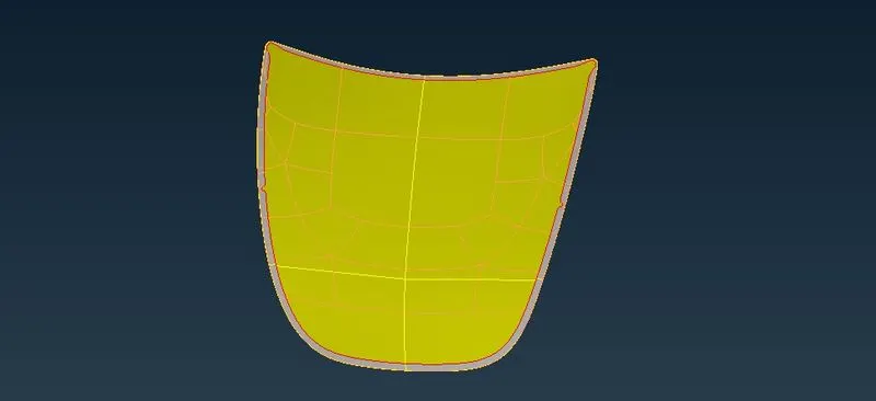
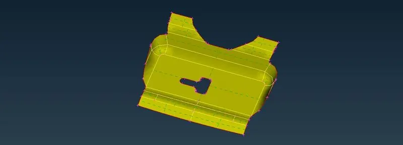
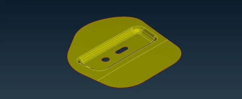
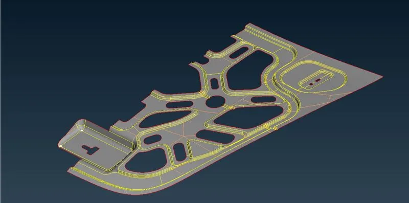
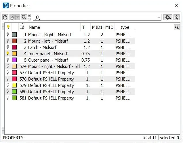
The Model has 5 different components such as Outer panel, Inner panel, Latch reinforcement, Right side mount reinforcement and Left side mount reinforcement.
The process of 2D meshing the components from scratch is as below:
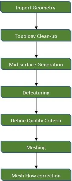
Import Geometry:
Go to File > Open > Select file to import
Topology clean-up:
- Initially when the model is opened, perform Checks > Geometry on each and every component that are present in the model to make sure there are no irregularities present. If any errors occur, we can use Auto fix to solve them or do it manually by using various commands in the Topo deck.
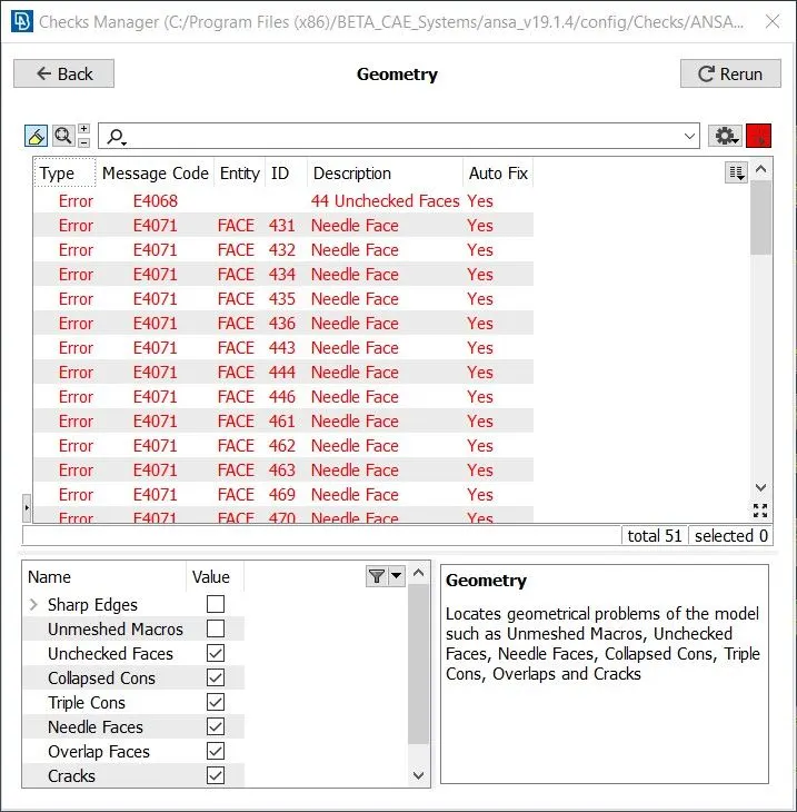
- After the geometry check is done, Measure command is used to estimate the thickness of the components.
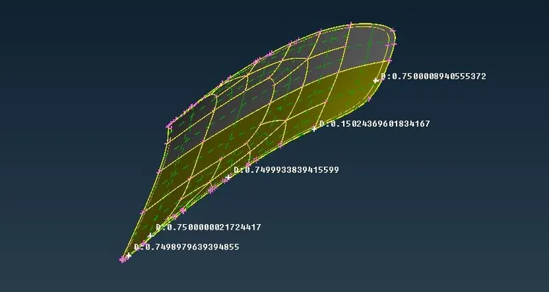
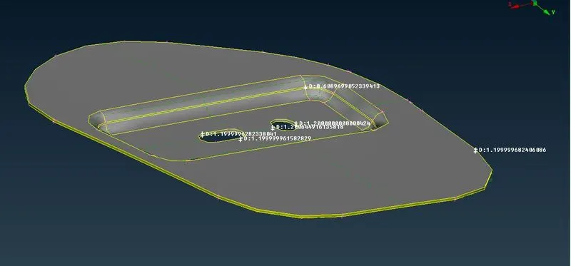
- At times when some of the features are not appearing in their original form, the Auxiliaries > Fine command can be used to increase the resolution at that particular area and check the original shape of the feature.
- Then, the Faces > Orientation command is performed to make sure that all the faces are in same orientation (i.e., positive or negative).
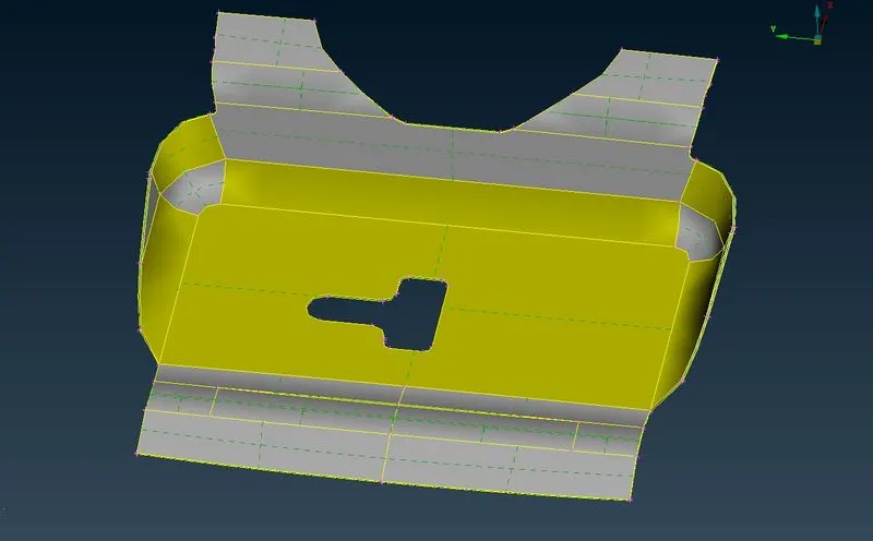
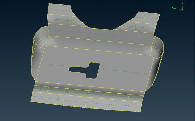
- We can also create individual Locks for different PIDs for better accessing of the components.
Mid-surfacing:
- To create the mid-surfaces, Midsurf > Skin command can be used as it automatically considers the thickness of the component.
- The Faces> Topo command can be used to make sure that all the adjoining mid-surfaces are stitched together.
- For identical/repetitive surfaces, Transform > Copy is used to replicate the generated mid-surface.
- To remove symmetric surfaces, use Faces > Rm.Dbl.
- After generating mid-surface for all the components, individual PIDs for the different components is created.
- Geometry check can be performed once again to eliminate any errors that are present.
Defeaturing:
- Switch to Mesh deck.
- Go to Perimeters > Length and Enter the mesh size as length.
- Perform Measure command at minute edges and make sure it is closer to required mesh size.
- Use Perimeters > Slide for all holes present in the model and align any one side of the hole parallel to the closest perimeter.
- Then use Hot points > Mark/Unmark command to fix the hole.
- Make sure that all the holes are having even number of edges.
- To change the number of edges, Perimeters > Number can be used.
- We can use Macros > Cut to split any large surfaces or to simplify the complex surfaces.
- After performing Cut operation, use Hot points > Insert to remove the excess Hot points.
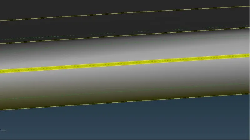
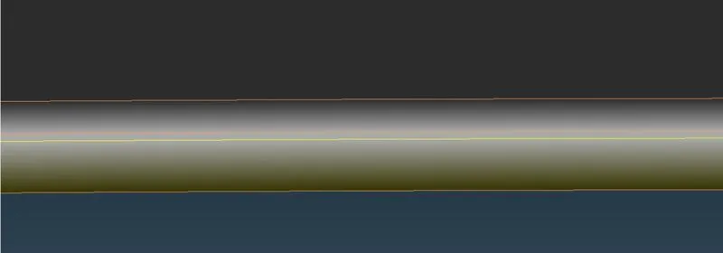
- Always capture the peak of the bead & fillet (using Cut option).
Define Quality Criteria:
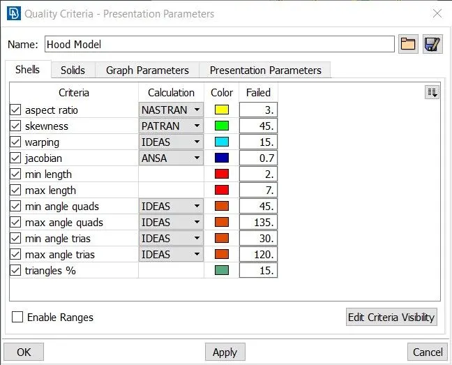
Press F11 to open Quality criteria window. Then, Select and define the required criteria.
Meshing:
- Open Mesh parameters and enter appropriate values.
- For meshing the surfaces, Use Best Mesh algorithm from the Mesh generation panel.
- Always start meshing from the features.
- To view the mesh quality, Toggle Hidden mode.
- Use Shell mesh > Reconstruct to reform the mesh elements.
- Use Shell mesh > Smooth to smoothen the mesh element structures.
- To copy the mesh generated on the features to other identical features, use Transform > Copy (delete the unmeshed identical features before using Copy option since it'll copy along with the geometric surfaces).
- Perform Topo after copying.
Some of the basic conditions to be kept in mind while meshing are as follows:
- No Tria elements should be present at the perimeter and the holes.
- No Tria elements should be connected back-to-back or present opposite to each other.
- No Tria elements should be on the features and fillets.
- Max no. of elements should be perpendicular to each other (Minimise wavy mesh flow patterns).
Mesh Flow Correction:
- Use Zone cut to create washer around holes.
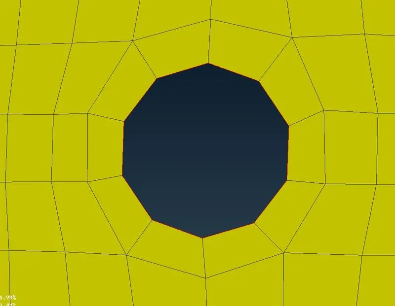
- Use Elements > Split command to move the Tria elements forward.
- Use Elements > Swap command to move the Tria elements sideward.
- Use Grids > Paste command to move the Tria elements backward.
- After meshing, Reconstructing & smoothing operation are completed, Use Macros > Join (change Reconstruct to Keep in options list).
- Stitch all the independent feature meshes using Paste option.
Learning Outcomes:
- Gained better fluency with the ANSA GUI.
- Acquired aptitude on identifying and improving failing and bad quality elements.
- Became familiar with various ANSA commands like Split, Swap, Paste, Origin, Smooth, Reconstruct, Cut, Edge2Perimeter, etcetera.
Conclusion:
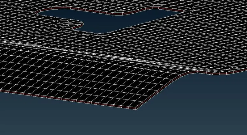
Thus, the given Hood model is meshed with 2D meshing technique satisfying the required Quality criteria by following all the necessary procedure.