Week 9-Creation of 1D Connectors Challenge
Aim-To attach the parts of given model using specific connectors after clean up and meshing said parts.
PROCEDURE
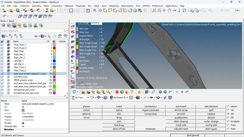
1. The model is cleaned up and meshed with proper mesh flow. The mesh type is mixed and element size is taken as 5 mm. It is a 2D mesh since the entire model comprises of extracted midsurfaces.
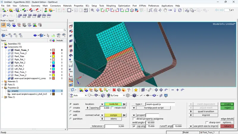
2.a. Right_Rail_2 & Front_truss_1:- Seam-Quad(angled+capped+L)
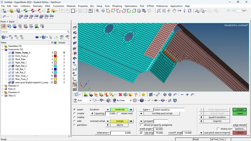
For this, we can isolate the Right_Rail_2 and Front_truss_1 surfaces and find the region of possible connection to add connectors.This is a seam connector so the seam option is selected. (2D > Connectors > seam),The location option lets us select which nodes will involve the connectors and the 'connect what' lets us select the components that need connecting. Furthermore, we need to specify the time of seam connector through 'type' where we can select 'seam-quad (angled+capped+L). If specified, we can alter other options like weld angle, cap angle and runoff angle. Furthermore, tolerance needs to be varied accordingly so the connector option can find the next part to connect and ensure realization.
3.The same process is followed in isolating and picking the nodes to be connected. The quad connectors is under the same seam options. It just needs to be selected from the 'type' menu.It's the same procedure again with picking the nodes and selecting the components and assigning the tolerance
c. Front_truss_2, Front_truss_1 & Right_Rail_1:- Spot weld with 3 Layers and 5 mm Diameter
Again, the particular components are isolated. This connector will involve 3 layers
The elements are selected along with the 3 layers. And the tolerance is assigned along with the diameter. The process is again, pretty straightforward.
d. Front_truss_2, Front_truss_1 & Left_Rail_1:- Hexa (Adhesive)
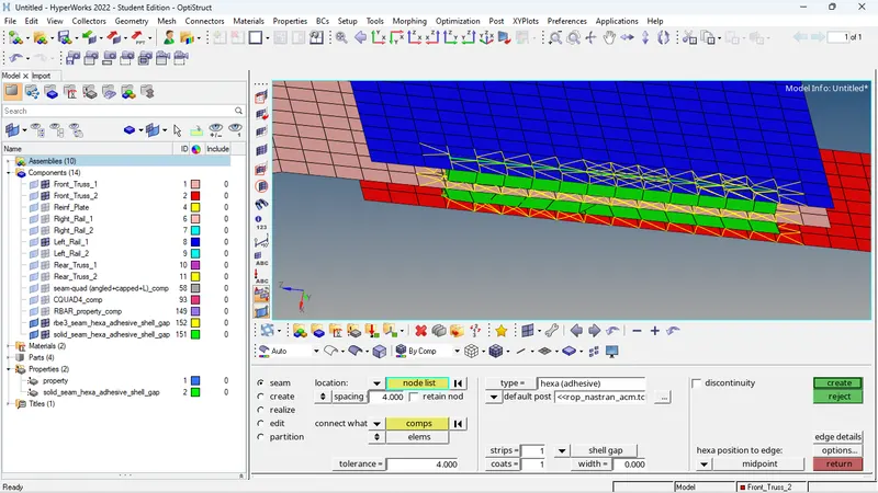
To access the adhesive connector, it is under the seam connector options. 2d > connectors > seam and the type needs to be hexa (adhesive). We again get to input the criteria and select the nodes and components.
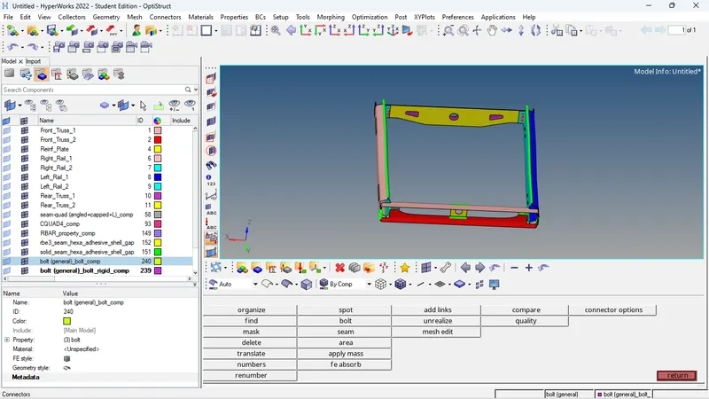
e. Rear_truss_2 & Right_Rail_2 & Rear_truss_2 & Left_Rail_2:- Bolt Connector
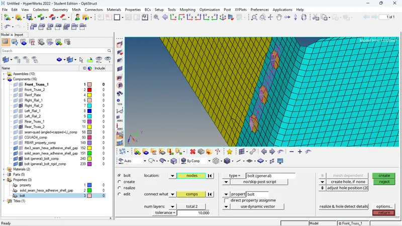
Similar process again. The two components to be connected are isolated and we pick the nodes through which the connectors will be placed. Since this is a bolt connector, two should be adequate. The bolt options can be accessed from the connectors menu (2D > connectors > bolt),We can assign the tolerance, select the nodes and components. Also, the 'create hole, if none' option is selected. For type, I have gone for bolt (CBAR).
f. Right_Rail_1 & Right_Rail_2:- Spot-weld with Rigid Elements & Left_Rail_1 & Left_Rail_2:- Spot-weld with Spring Elements
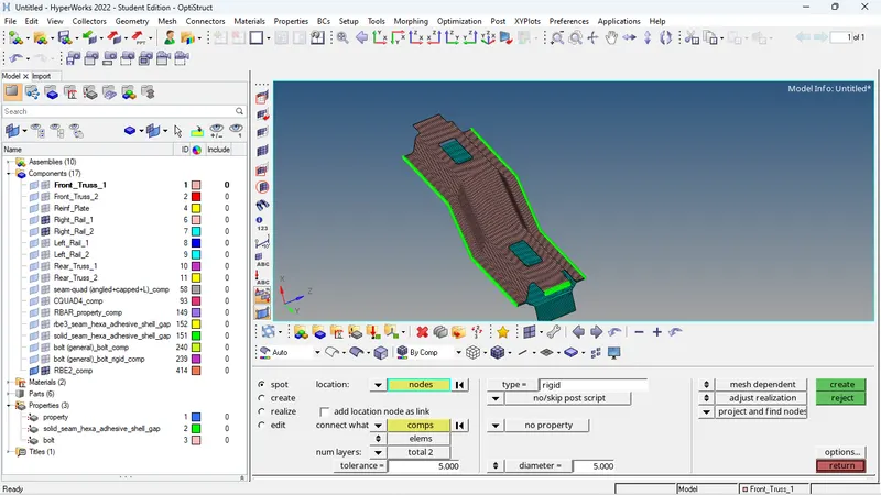
The elements are isolated and all the nodes along a single line of the entire components are selected for spot welding (on both sides). The only difference being the type in these cases. The first case will have 'rigid' for type and the second will have 'spring'.
3. The rest of the components are joined using suitable connectors based off information from previous connectors used in similar regions of other components.
RESULT
The given model was meshed and after meshing, the components included were connected using specified connectors and were realized. Accordingly, appropriate connectors were used on other components of the same model.