Week 9-Creation of 1D Connectors Challenge
AIM: To Create 1D connectors for given components by different types of connectors
For the component, they have given some quality criteria to assign for the element as given below:
|
S.N |
Quality Criteria |
Value |
|
1 |
Aspect Ratio |
5 |
|
2 |
Skewness |
45 |
|
3 |
Warping |
15 |
|
4 |
Taper |
0.5 |
|
5 |
Min. Length |
2 Units |
|
6 |
Max. Length |
8 Units |
|
7 |
Min angle Quad |
45 |
|
8 |
Max angle Quad |
135 |
|
9 |
Min angle Tria |
30 |
|
10 |
Max angle Tria |
110 |
|
10 |
Tria % |
15 |
Create a connector and Attach the various parts of the given model :
1. Right_Rail_2 & Front_truss_1:- Seam-Quad(angled+capped+L)
2. Left_Rail_2 & Front_truss_1:- Quad elements
3. Front_truss_2, Front_truss_1 & Right_Rail_1:- Spot weld with 2 Layers and 5 mm Diameter
4. Front_truss_2, Front_truss_1 & Left_Rail_1:- Hexa (Adhesive)
5. Rear_truss_2 & Right_Rail_2:- Bolt Connector
6. Rear_truss_2 & Left_Rail_2:- Bolt Connector
7. Right_Rail_1 & Right_Rail_2:- Spot-weld with Rigid Elements
8. Left_Rail_1 & Left_Rail_2:- Spot-weld with Spring Elements
9. Rest all the components left Join them with suitable connectors.
Procedure:
Setting up the Model:
Import the model into the hypermesh as a .hm file to it.
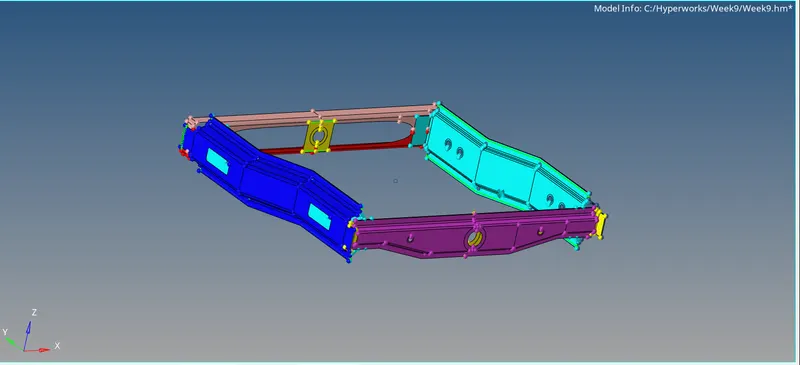
Here each component are been meshed separately as per topology errors and defeatured using the manual auto cleanup method.
To clean geometrical errors: "Geom -> auto cleanup -> Set parameter -> cleanup"
2D surface meshing & mesh refine:
To generate a 2D shell mesh over each component
2D -> Automesh -> Surf(display) -> Target length as 5 -> choose mesh "Mixed" -> mesh
If there is any quality error as mentioned above, select the element to rebuild or elems check.
For the surface, we have to build up the mesh for every component:
Front Truss 1:

Front Truss 2:

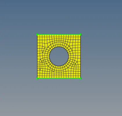
Reinf Plate:
Right Rail 1:
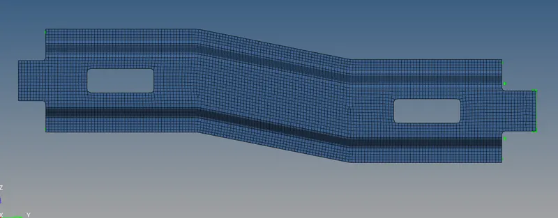
Right Rail 2:
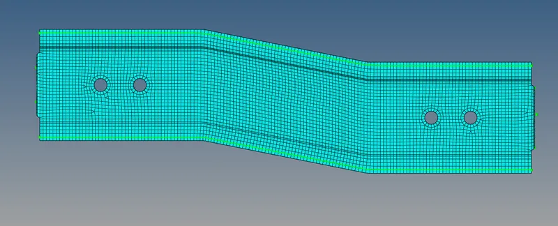
Left Rail 1:
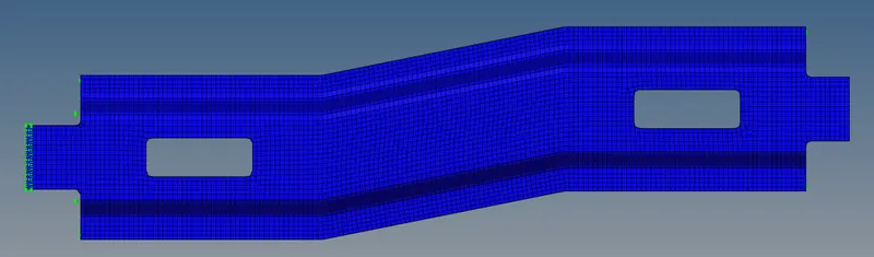
Left Rail 2:
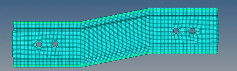
Rear Truss 1:
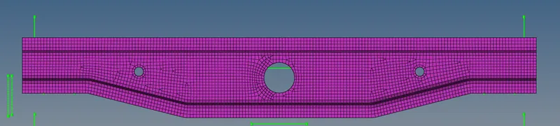
Rear Truss 2:

Assigning the property card to the components:
To create the property for all the components and assign the thickness to it.
Here I have assigned a thickness of 1mm as steel to it, as PSHELL.
Each card is assigned the property card which is linked to the material card.
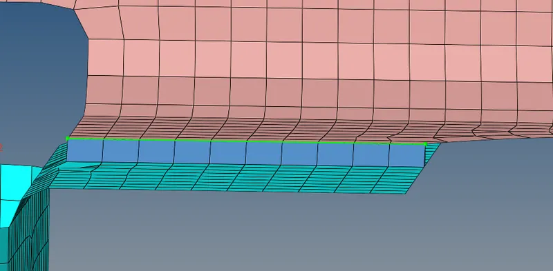
1. Right_Rail_2 & Front_truss_1:- Seam-Quad(angled+capped+L):
First, select the Element to create a Seam Quad as angled+capped+L, and then give the tolerance as 10.
Selecting the Components to create a Seam element among both components.
Select the "Imprint" enable to mesh it properly.
To realize the mesh of the component.
2. Left_Rail_2 & Front_truss_1:- Quad elements:
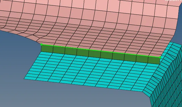
To create a seam weld: Connectors -> seam
Select the nodes (by path) on one of the components.
Tolerance = Specify the search distance (10mm).
Select the two components and keep the imprint in check.
The weld type is set as a quad and the spacing (distance between the two adjacent weld elements) is kept as 5mm.
3. Front_truss_2, Front_truss_1 & Right_Rail_1:-
Spot weld with 2 Layers and 5 mm Diameter:
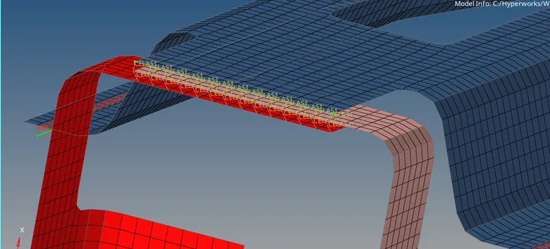
To create a spot weld: 2D -> connectors -> spot -> type -> weld.
Select all the required nodes where the location of the spot weld has to be placed.
Then select all the 3 components.
Specify a diameter of 5mm and a number of layers as 3.
NOTE: Since the layer is set as 3, a minimum of three components have to be selected and in case only two components are present then the layer has to be set as auto.
4. Front_truss_2, Front_truss_1 & Left_Rail_1:-
Hexa (Adhesive):
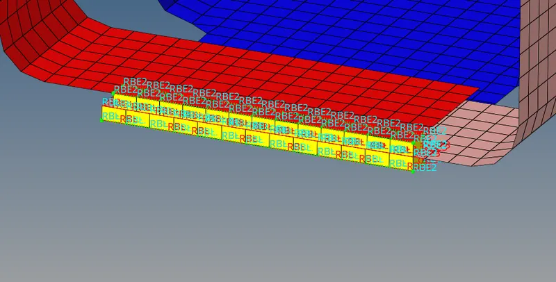
To create a Hexa element in the Front truss 1,2 & Left rail over it.
Select the elements to create a Hexa element "Area -> Choose the elems -> Hex RBE2 & RBE3 -> select the component".
Select the specified tolerance of 10mm.
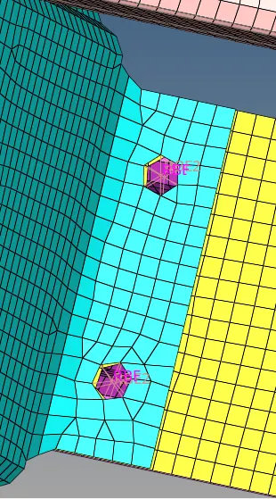
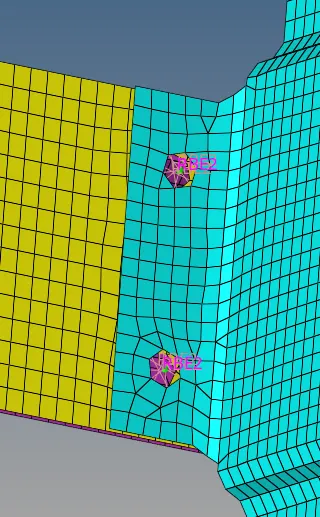
5. Rear_truss_2 & Right_Rail_2:-
Bolt Connector:
To create a bolt connector: Connectors - bolt
Specify the location of the bolt by selecting two single nodes at a certain distance in one of the components since two bolt connectors are being realized.
Select the two components which have to be fixed by the bolt.
Select the option to create a hole to define the bolt as a physical element (Note that this will modify and alter the neighboring mesh).
Specify the search length (about 10mm).
6. Rear_truss_2 & Left_Rail_2:-
Bolt Connector
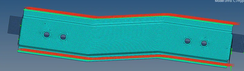
7. Right_Rail_1 & Right_Rail_2:-
Spot-weld with Rigid Elements:
Similar to previous spot weld creation, this spot weld is created using rigid instead of weld.
To create a spot weld: "2D -> connectors -> spot -> type -> rigids.
Select all the required nodes where the location of the spot weld has to be placed. (by path).
Then select all the 2 components.
Specify the diameter and number of layers as 2 (since only two components are present).
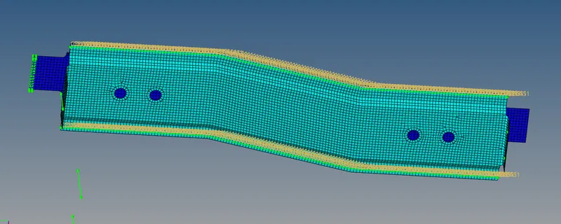
8. Left_Rail_1 & Left_Rail_2:-
Spot-weld with Spring Elements:
As in the above component, in here in this Spot weld is created using Spring instead of the weld.
To create a spot weld: "2D -> Connecters -> Spot -> Springs"
Select all the required nodes where the location of the spot weld has to be placed as "By Path".
After that select the 2 components.
Specify the diameter and no of layers to auto.
9. Rest all the components left Join them with suitable connectors:
For the below elements here I have chosen the "Quad".
From the Seam -> Quad -> nodes by path -> select the tolerance -> create.
If the connectors are been created it shown in green color.
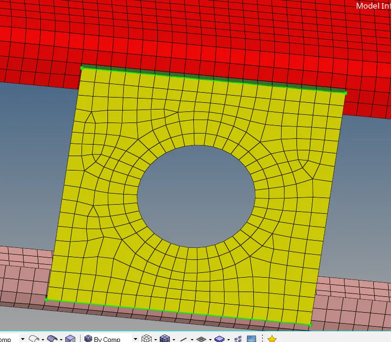
Here Left rail 1 & Rear Truss 2 are been created as Quad elements:
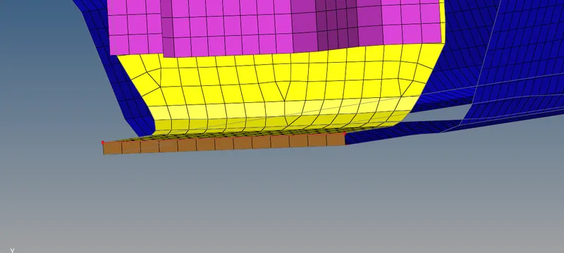
A seam weld with a Vertical+angled type is created as shown below:
"2D -> Connectors -> seam -> Quad(Vertical+Angled).
Conclusion:
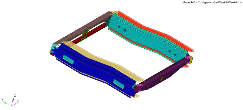
Here every component have been meshed as per quality criteria & required connection are been created & realized it, here in below image I have attached the entire connection which was made in the component shown: