SIMULINK Week -2 making a simulink model of a doorbell & Thermistor sensor to Turn On or OFF Fan
AIM:
- Make a Simulink model of a Doorbell using a solenoid block with the following details
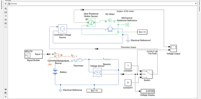
2. Use a thermistor to sense the temperature of a heater & turn on or turn off the fan as per the below conditions
Make a Simulink model of a Doorbell using a solenoid block with the following details
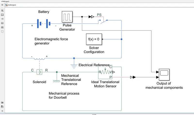
In this model, we are going to simulate a doorbell using a solenoid block by using a different type of Simulink and sim space block diagram.
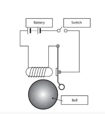
In the above figure, this Block diagram is constructed by using solenoids to act as an electromagnet field in which current passes through the wires as a magnetic field is generated around it, which will attract magnetic materials.
DOORBELL USING SOLENOID:
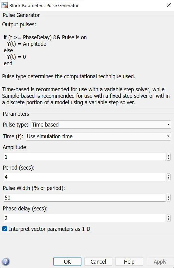
The Solenoid is an electromagnetic source. An ideal translational motion sensor is used to sense the motion of the solenoid as a mechanical convert. The pulse generator is used to generate values in a graphical form in which the PS switch is used to sub-connect with the pulse generator. parameters such as Amplitude, Periods(in secs), Pulse Width, Delay of the frequency are given.
There are 2 categories in the construct of the Doorbell simulation.
i) Electromagnetic force generator
ii) Mechanical Process for a doorbell
i) Electromagnetic force generator
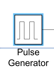
PULSE GENERATOR:
It is used to generate both input and output in the waveform, in that various inputs are given to it to perform such operation as per requirements.
Battery:

It is the main power source to perform the operation which is connected to Switch as a positive terminal.
Simulink PS- Converter:
This block is used to connect the Simulink block to the Simspace block as an inter-connecter, in which the pulse generator is connected at one end and another is connected to the switch.
Solver Configuration:
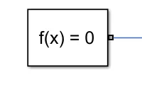
The Solver Configuration block specifies the solver parameters that your model needs before you can begin the simulation. Each topologically distinct Simscape block diagram requires exactly one Solver Configuration block to be connected to it.
Electrical Reference:
The Electrical Reference block represents an electrical ground. Electrical conserving ports of all the blocks that are directly connected to the ground must be connected to an Electrical Reference block. A model with electrical elements must contain at least one Electrical Reference block.
"The output of this whole circuit is been connected to Scope which acts as an output of the pulse generator"
ii) Mechanical Process for a doorbell:
Solenoid:
The solenoid is modeled as an inductance whose value L depends on the plunger position x. The back emf for a time-varying inductance is given by: As L depends on x, this becomes: can be derived from manufacturer force-stroke data using the relationship: can then be integrated to get L as a function of x.
This is also used to connect to different processes to compute.
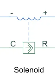
Ideal Translational Motion Sensor:
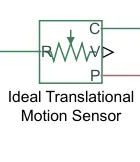
The Ideal Translational Motion Sensor block represents a device that converts an across variable measured between two mechanical translational nodes into a control signal proportional to velocity or position.
PS Simulink Convertor:

"The output of this whole circuit is been connected to Scope which acts as an output"
OUTPUT:
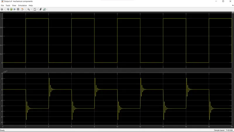
Output is been attached below by performing the block diagram.
Input of Parameters:
1st Graph represents the pulse generator block
2nd Graph represents the plunger varies for 20sec with an interval of 2sec in between.


The Resistor block models a linear resistor described with the following equation:
V=I·R
where:
-
V is voltage.
-
I is current.
- R is resistance.
By convention, the voltage across the resistor is given by V(+) – V(–), and the sign of the current is positive when flowing through the device from the positive to the negative terminal.
Switch:

To turn on or off the terminal we need a switch, in Simulink, there are many types of switches, for this function I have chosen two ways switch for this operation.
Controlled Voltage Source:

The Controlled Voltage Source block converts a Simulink input signal into an equivalent voltage source. The generated voltage is driven by the input signal of the block. You can initialize the Controlled Voltage Source block with a specific AC or DC voltage.
Ideal rotational motion sensor:

The Ideal Rotational Motion Sensor block represents an ideal mechanical rotational motion sensor, that is, a device that converts a variable measured between two mechanical rotational nodes into a control signal proportional to angular velocity or angle.
DC motor:

Basically motor is used to convert electrical output that will convert it into mechanical terms to perform that rotor runs.
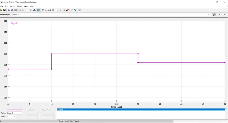
Input of Signal Builder:
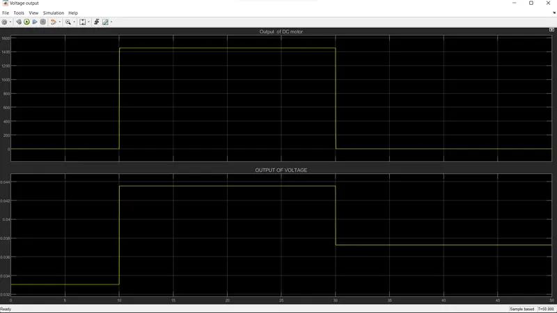
Temperature source: 20 °C from 0 to 10 seconds, 27 °C from 10 to 30 seconds, 23 °C from 30 to 50 seconds
Fan conditions: ON if the temperature is above 25 °C, OFF otherwise
OUTPUT OF VOLTAGE & DC MOTOR(rpm):