Week 9-Creation of 1D Connectors Challenge
OBJECTIVE :
To create the mesh on the given model and create the connector and attachment of various components.
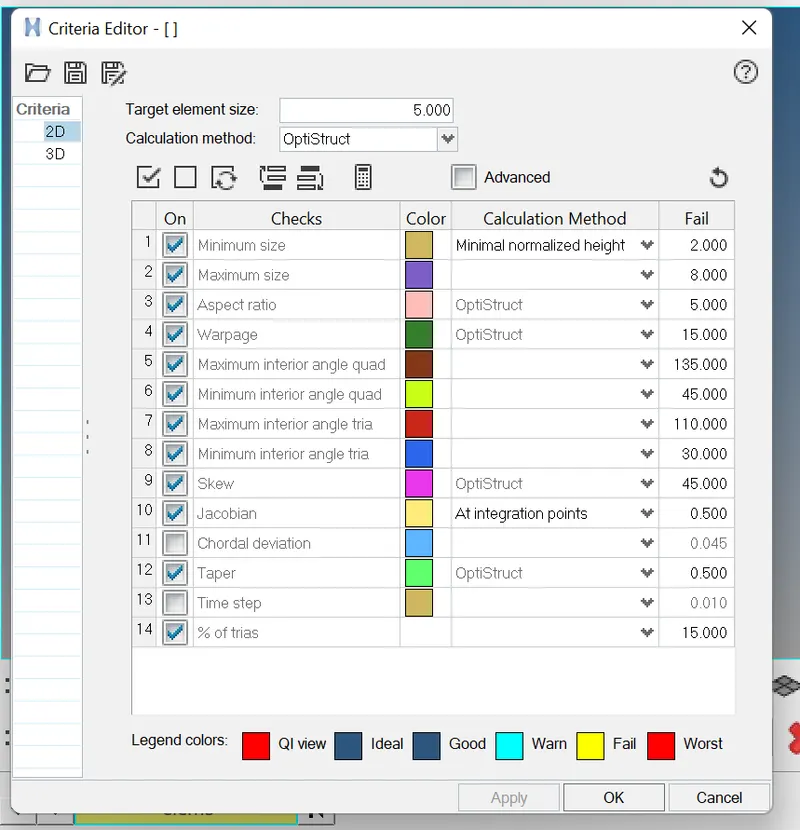
Target Element size - 5 Units
|
S.N |
Quality Criteria |
Value |
|
1 |
Aspect Ratio |
5 |
|
2 |
Skewness |
45 |
|
3 |
Warping |
15 |
|
4 |
Taper |
0.5 |
|
5 |
Min. Length |
2 Units |
|
6 |
Max. Length |
8 Units |
|
7 |
Min angle Quad |
45 |
|
8 |
Max angle Quad |
135 |
|
9 |
Min angle Tria |
30 |
|
10 |
Max angle Tria |
110 |
|
10 |
Tria % |
15 |
Create connector and Attach the various parts of the given model
1. Right_Rail_2 & Front_truss_1:- Seam-Quad(angled+capped+L)
2. Left_Rail_2 & Front_truss_1:- Quad elements
3. Front_truss_2, Front_truss_1 & Right_Rail_1:- Spot weld with 2 Layers and 5 mm Diameter
4. Front_truss_2, Front_truss_1 & Left_Rail_1:- Hexa (Adhesive)
5. Rear_truss_2 & Right_Rail_2:- Bolt Connector
6. Rear_truss_2 & Left_Rail_2:- Bolt Connector
7. Right_Rail_1 & Right_Rail_2:- Spot-weld with Rigid Elements
8. Left_Rail_1 & Left_Rail_2:- Spot-weld with Spring Elements
9. Rest all the component left Join them with suitable connectors
CAD MODEL:
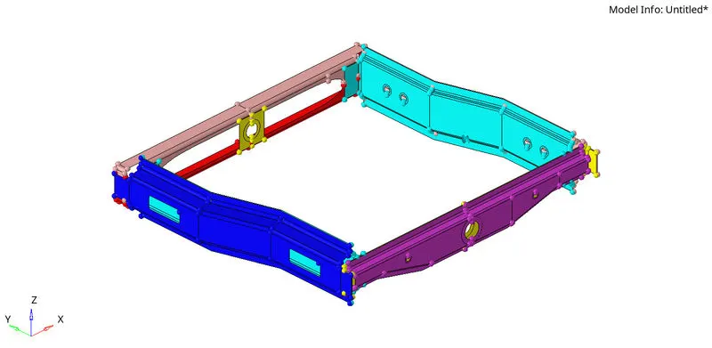
PROCEDURE :
1. Import the cad model in hypermesh.
2. Make a 2D mesh on the every components of the model by the given quality criteria.
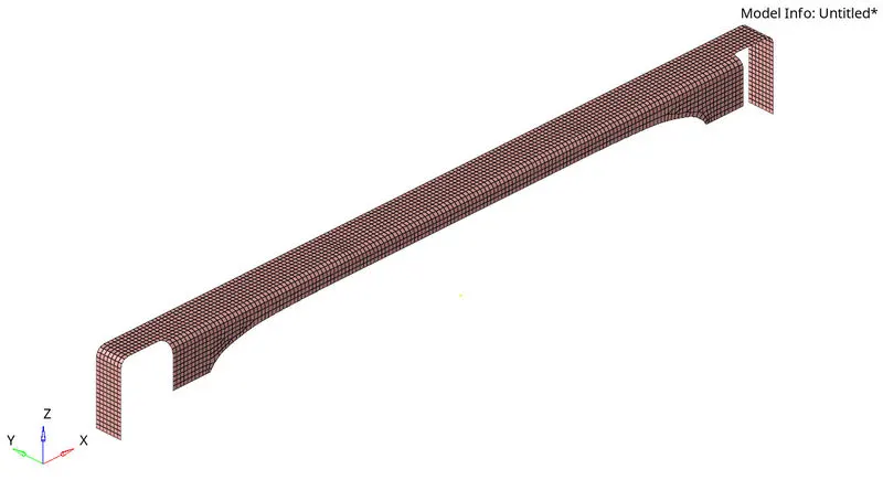
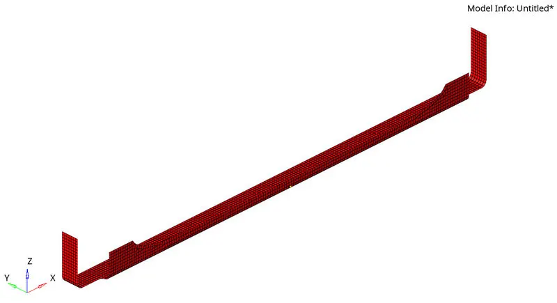
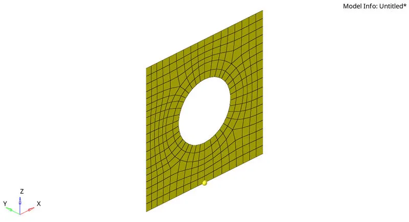
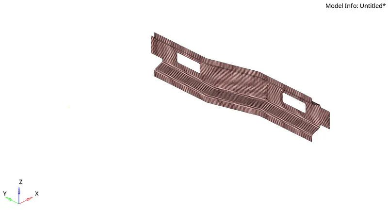
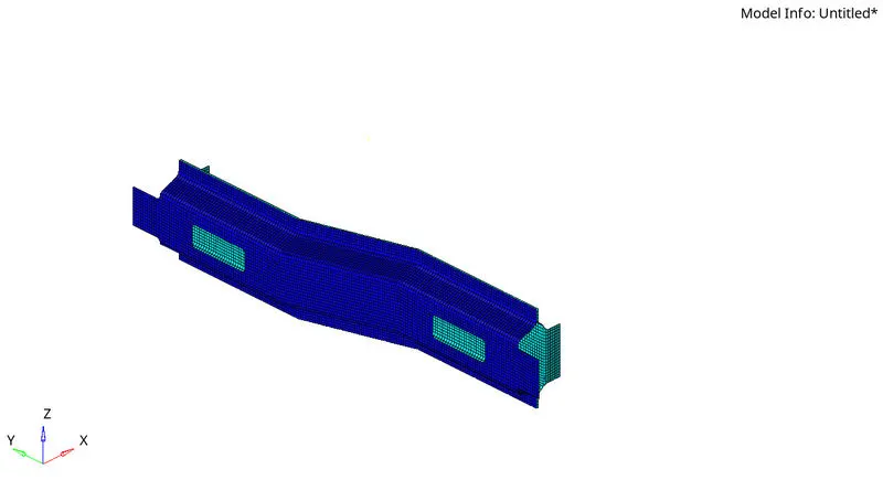
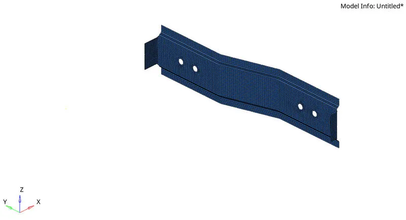
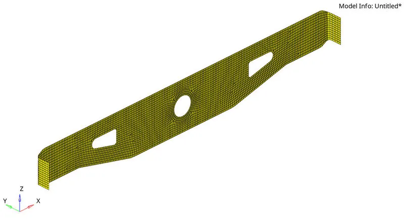
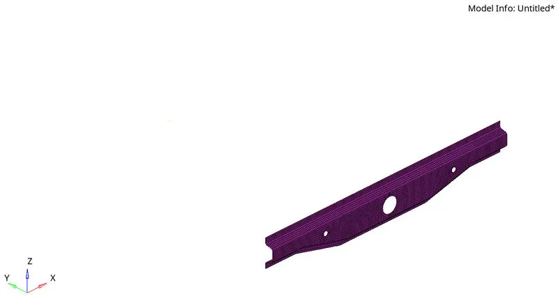
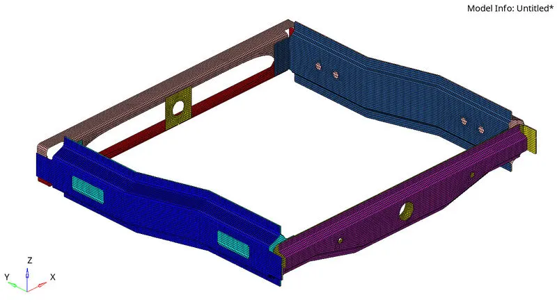
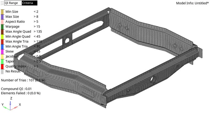
Here the given components are meshed with 0 % of failing elements.
CONNECTION :
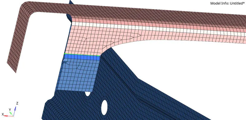
1. Right_Rail_2 & Front_truss_1:- Seam-Quad(angled+capped+L)
- To create a seam weld: Connectors - seam
- Select the nodes (by path) on one of the component and tolerance = Specify the search distance (10mm)
- Select the two components and keep the imprint check on
- weld type is set as seam-quad (angled+capped+L)
- The spacing is set a 5mm. Spacing defines the distance between the two adjacent weld
elements
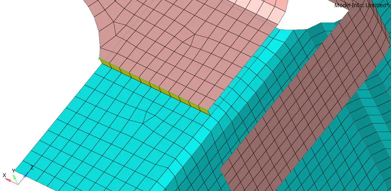
2. Left_Rail_2 & Front_truss_1:- Quad elements
- To create a seam weld: Connectors - seam
- Select the nodes (by path) on one of the components and tolerance = Specify the search distance (10mm).
- Select the two components and keep the imprint check on.
- weld type is set as quad and the spacing (distance between the two adjacent weld
elements) is kept as 5mm.
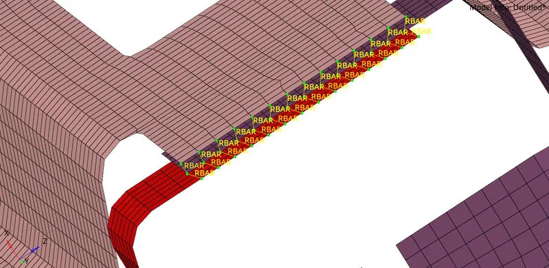
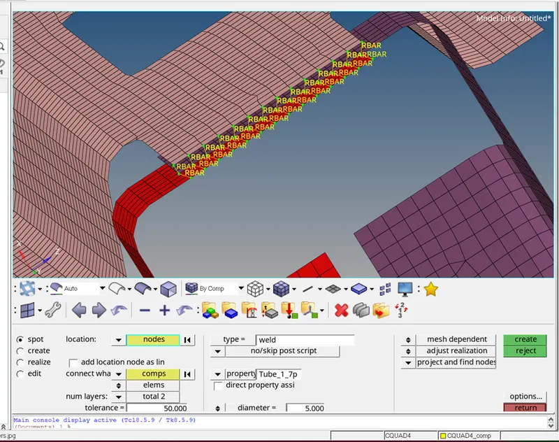
3. Front_truss_2, Front_truss_1 & Right_Rail_1:- Spot weld with 2 Layers and 5 mm Diameter
- To create a spot weld: 2D - connectors - spot - type=weld
- Select all the required nodes where the location of the spot weld has to be placed.
- Then select all the 3 components
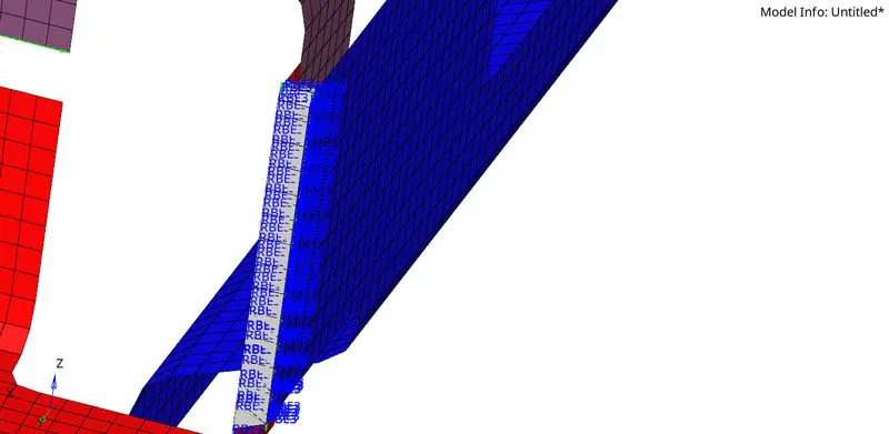
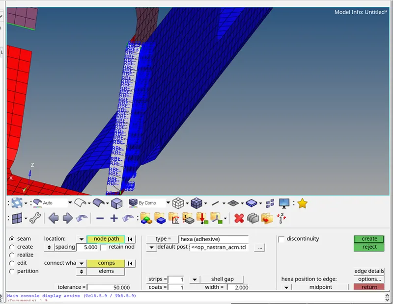
4. Front_truss_2, Front_truss_1 & Left_Rail_1:- Hexa (Adhesive)
- To create a seam weld: Connectors - seam
- Select the nodes (by path) on one of the component and tolerance = Specify the search distance (10mm).
- Select the two components and keep the imprint check on.
- weld type is set as hexa (adhesive) under the weld type category.
- The strips and coats of the weld can be altered. In this case, the strip is set as 2 and a single
coating is specified and width is 2 mm.
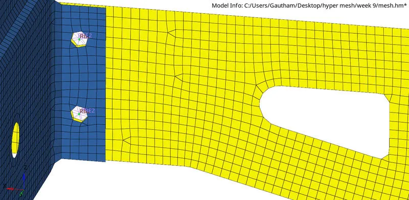
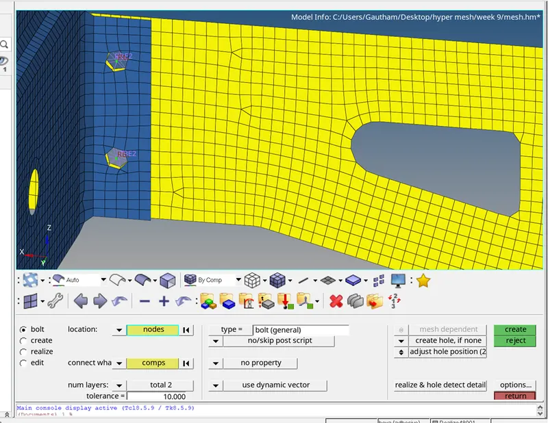
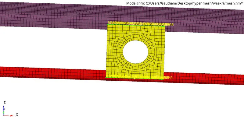
5. Rear_truss_2 & Right_Rail_2:- Bolt Connector
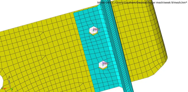
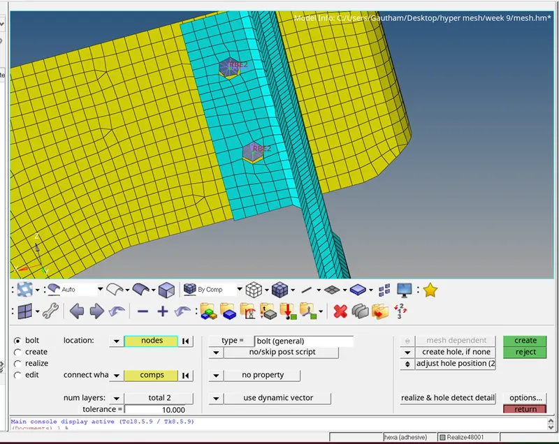
- Specify the location of the bolt by selecting two single nodes at a certain distance in one of the component since two bolt connectors are being realised.
- Select the two components which has to be fixed by the bolt.
- Specify the search length (about 10mm)
- If the hole is not there select the option create hole,if none.
- The realised bolt connection is shown below.
6. Rear_truss_2 & Left_Rail_2:- Bolt Connector
Same the step followed by previous Rear_truss_2 & Right_Rail_2.
7. Right_Rail_1 & Right_Rail_2:- Spot-weld with Rigid Elements
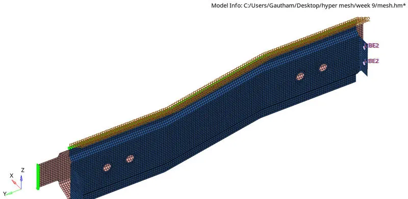
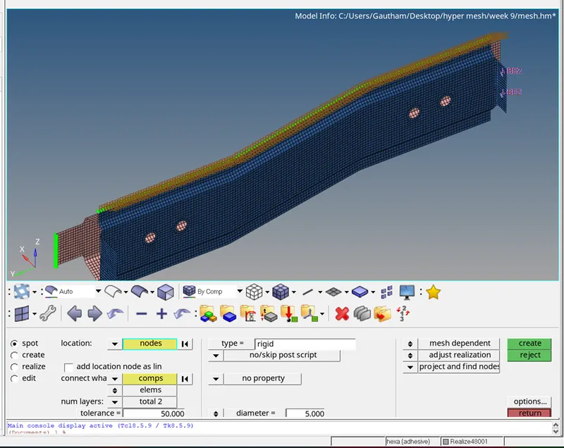
- To create a spot weld: 1D - connectors - spot - type=rigids
- Select all the required nodes where the location of the spot weld has to be placed.
- Specify the diameter and number of layers as 2.
- select the components.
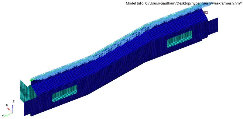
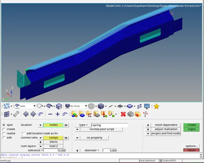
8. Left_Rail_1 & Left_Rail_2:- Spot-weld with Spring Elements
- To create a spot weld: 1D - connectors - spot - type=spring
- Select all the required nodes where the location of the spot weld has to be placed.
- Specify the diameter and number of layers as 2.
- select the components.
9. Rest all the component left Join them with suitable connectors
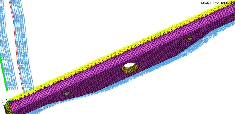
FINAL MODEL IMAGE:
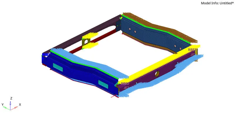
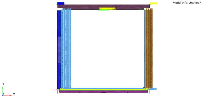
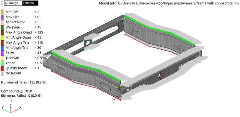
RESULT :
The given model is meshed with the given qality criteria and 1D connections are created and the parts were attached with various connections.