Week 9-Creation of 1D Connectors Challenge
CONNECTIONS.
What are connectors?
Connectors are the geometric entities which is required to join two parts or surfaces. Connection can be seam weld, spot weld, adhesives, masses and bolt etc. Proper realization of connection is very important. If, connection is not properly realized than it will throw errors while carrying analysis. The surface or structure will be hanging.
AIM: To deploy connection such as bolt, seam, adhesives and spot for frame assembly.
PROCEDURE: 1) Open the frame assembly in hyper works desktop student version 2021 and import the model.
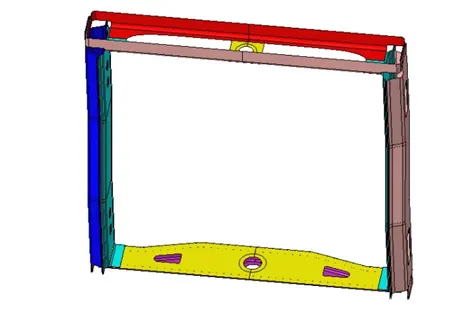
2) The mid-surface of the given assembly is already generated. We will proceed with meshing the component one by one.
3) Enter the quality criteria value.
PREFERENCES→ CRITERIA FILE → ENTER THE VALUES → APPLY →OK.
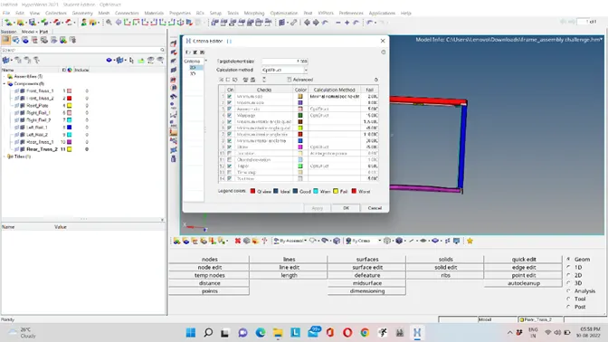
4) Now generate the mesh on each component by specifying the target length as 5.
2D→ AUTOMESH (F12) → SELECT THE SURFACE → ENTER TARGET VALUE → CREATE.
We can use rebuild option to improve the mesh flow in one short.
2D→ REBUILD → SELECT THE ELEMENTS→ REBUILD.
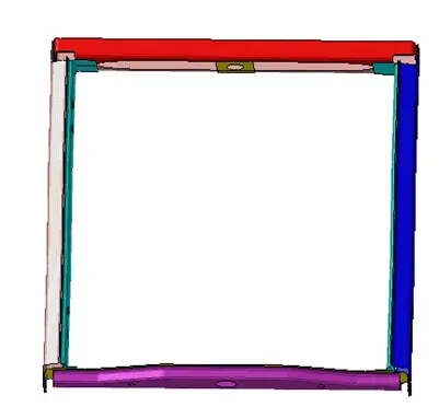
Hence, mesh is generated.
Now we will do connections.
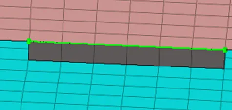
1)For right rail 2 and front truss 1 component we will deploy seam quad (angled + capped +l)
1D→ CONNECTORS→ SEAM→ SELECT THE TYPE OF ELEMENT → SPECIFY SPACING (SAME AS TARGET) → ENTER THE TOLERANCE VALUE (SAY 50) → SELECT THE NODES → SELECT THE COMPONENTS → SPECIFY RUN OFF ANGLE, CAP ANGLE AND WELD ANGLE → CREATE.

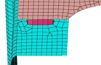
Hence, the connection is realized now re mesh the mesh flow which is affected.
2) For left rail 2 and front truss 1 we will deploy seam weld with quad elements.
Select the element type as quad. Rest of the procedure will be same.
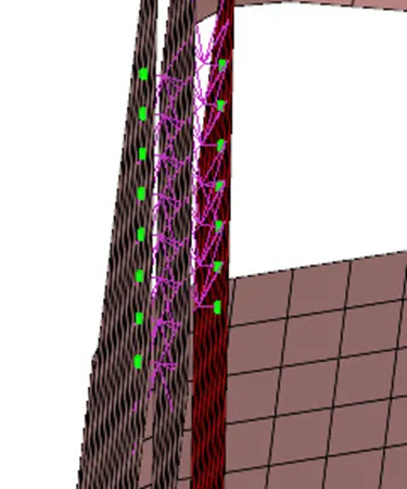
3) for front truss 1 and 2 and right rail 1 we will be deploying spot weld with number of layers as 2 and the diameter as 5.
1D→ CONNECTORS → SPOT → SELECT THE NODES → SELECT THE COMPONENTS → WE CAN YOU THE ELEMENT TYPE AS RIGID → ENTER THE DIAMETER VALUE AS 5→ CREATE.
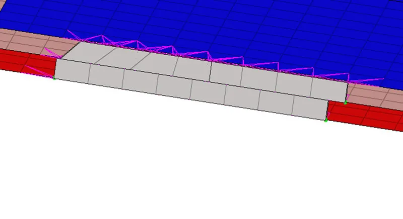
4) For front truss 1 and 2 and left rail 1 we will be creating hexa adhesive seam weld.
1D→ CONNECTORS → SEAM → SELECT THE ELEMENT TYPE AS HEXA ADHESIVE → SELECT THE NODES→ SELECT THE COMPONENTS → SPECIFY THE SPCAING AND THE TOLERANCE → CREATE
5) Rear truss 2 and right rail 2 and also between rear truss 2 and left rail 2 we will be generating bolt connection.
1D→CONNECTOR → BOLT→ SELECT THE NODES→ SELECT THE COMPONENT → CREATE HOLE, IF NONE → SPECIFY THE TOLERANCE VALUE → ELEMENT TYPE (BOLT GENERAL) → CREATE.


6) For right rail 1 and 2 we will be deploying spot mesh with rigid elements.
Same procedure needs to be followed as we did previously just change the element type.

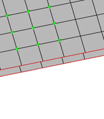
7) For left rail 1 and 2 we will be deploying spot weld with spring element.


Hence, connection is generated.
If any connection failed to realize we can change the tolerance value, spacing or the proper selection of the nodes.
To see the connection tree:
VIEW→ BROWSER→ HYPERMESH→ CONNECTORS
Now save the component.
LEARNING OUTCOMES: 1) To deploy different type of connections such as spot, seam, adhesives and bolt.
2) How to realise, if any connection failed to realised.
3) Why connection is needed.
CONCLUSION: Hence, connection for the frame assembly is generated.