Week 9-Creation of 1D Connectors Challenge
AIM :
To mesh the given geometry by the given quality parameters with target element size as 5 units.Create connector and Attach the various parts of the given model.
OBJECTIVES :
a) mesh the given geometry with,
Target Element size - 5 Units
|
S.N |
Quality Criteria |
Value |
|
1 |
Aspect Ratio |
5 |
|
2 |
Skewness |
45 |
|
3 |
Warping |
15 |
|
4 |
Taper |
0.5 |
|
5 |
Min. Length |
2 Units |
|
6 |
Max. Length |
8 Units |
|
7 |
Min angle Quad |
45 |
|
8 |
Max angle Quad |
135 |
|
9 |
Min angle Tria |
30 |
|
10 |
Max angle Tria |
110 |
|
10 |
Tria % |
15 |
b) Create connector and Attach the various parts of the given model
1. Right_Rail_2 & Front_truss_1:- Seam-Quad(angled+capped+L)
2. Left_Rail_2 & Front_truss_1:- Quad elements
3. Front_truss_2, Front_truss_1 & Right_Rail_1:- Spot weld with 2 Layers and 5 mm Diameter
4. Front_truss_2, Front_truss_1 & Left_Rail_1:- Hexa (Adhesive)
5. Rear_truss_2 & Right_Rail_2:- Bolt Connector
6. Rear_truss_2 & Left_Rail_2:- Bolt Connector
7. Right_Rail_1 & Right_Rail_2:- Spot-weld with Rigid Elements
8. Left_Rail_1 & Left_Rail_2:- Spot-weld with Spring Elements
9. Rest all the component left Join them with suitable connectors
PROCEDURE :
a) for meshing the given geometry,
1. open the given model named frame assembly welding by going through, file - open - model - select file and open.also make the component as by topo and by component option for proper view.
2. visually inspect the model for any missing surfaces,free edges and non manifold lines.
3. make the model in to the wire frame mode and enable suitable visualization options and find out all the free edges and missed surfaces.
4.clear all the geometrical errors with suitable options.
5. also use the toggle edge option by going through, quick edit - toggle edge - apply tolerence - select free edges and clear it.
6. go to edge edit and replace unwanted free edges.
7. after making geometry cleanup go to meshing.before meshing toggle the ines that are fail to the minimum length.toggle all the unwanted lines and prepare a neat geometry to mesh.
8.after that apply the given quality criterias.for that go to, preference - criteria file settings - 2D - apply quality - ok.
9.then select the surfaces and mesh by going through 2D - automesh - srfaces - mixed - mesh.
10.mesh all the components and clear all the quality errors.rebuild the mesh for getting etter mesh flow and cear quality.for that go to, 2D - rebuild mesh - slect elements/surfs - edit parameters - rebuild.
11.by going through quaity index - clean up tools - smooth/place node/swap edge/node optimize/element optimize..etc clear all the quality criterias and improve the mesh.
12.also use replace node,combine,align options to improve the quality of the mesh.
b) for Create connector and Attach the various parts of the given model.
1. Right_Rail_2 & Front_truss_1:- Seam-Quad(angled+capped+L)
for connecting the components by Seam-Quad(angled+capped+L) go to, 2D - connectors - seam - node list - components - spacing - tolerence - type - Seam-Quad(angled+capped+L) - remesh - create.
2. Left_Rail_2 & Front_truss_1:- Quad elements
for connecting the components by quad elements, go to for connecting the components by Seam-Quad(angled+capped+L) go to, 2D - connectors - seam - node list - components - spacing - tolerence - type - quad - remesh - create.
3. Front_truss_2, Front_truss_1 & Right_Rail_1:- Spot weld with 2 Layers and 5 mm Diameter
for connecting the components by Spot weld with 2 Layers and 5 mm Diameter , go to 2D - connectors - spot - nodes - component - tolerence - type - weld - diameter - create.
4. Front_truss_2, Front_truss_1 & Left_Rail_1:- Hexa (Adhesive)
for connecting the components by Hexa (Adhesive) , go to 2D - connectors - seam - node list - components - spacing - tolerence - type - Seam- hexa (adhesive) - remesh - create.
5. Rear_truss_2 & Right_Rail_2:- Bolt Connector
for connecting the components by Bolt Connector , go to 2D - connectors - bot - nodes - components - tolerence - type - create hole,if none - create.
6. Rear_truss_2 & Left_Rail_2:- Bolt Connector
for connecting the components by Bolt Connector , go to 2D - connectors - bot - nodes - components - tolerence - type - create hole,if none - create.
7. Right_Rail_1 & Right_Rail_2:- Spot-weld with Rigid Elements
for connecting the components by Spot weld with rigid elements , go to 2D - connectors - spot - nodes - component - tolerence - type - rigid - diameter - create.
8. Left_Rail_1 & Left_Rail_2:- Spot-weld with Spring Elements
for connecting the components by Spot weld with rigid elements , go to 2D - connectors - spot - nodes - component - tolerence - type - spring - diameter - create.
9. Rest all the component left Join them with suitable connectors.
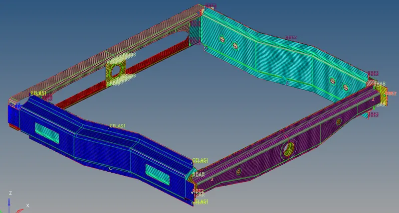
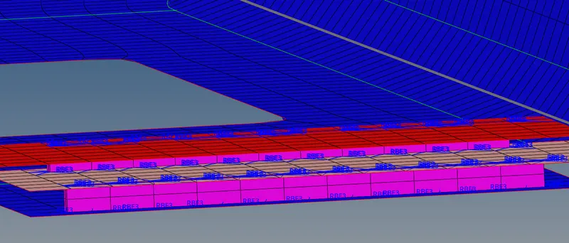
create all the other remaining components with suitable connections like bolt,spot weld,quad elements,spot with rigid or spring elements.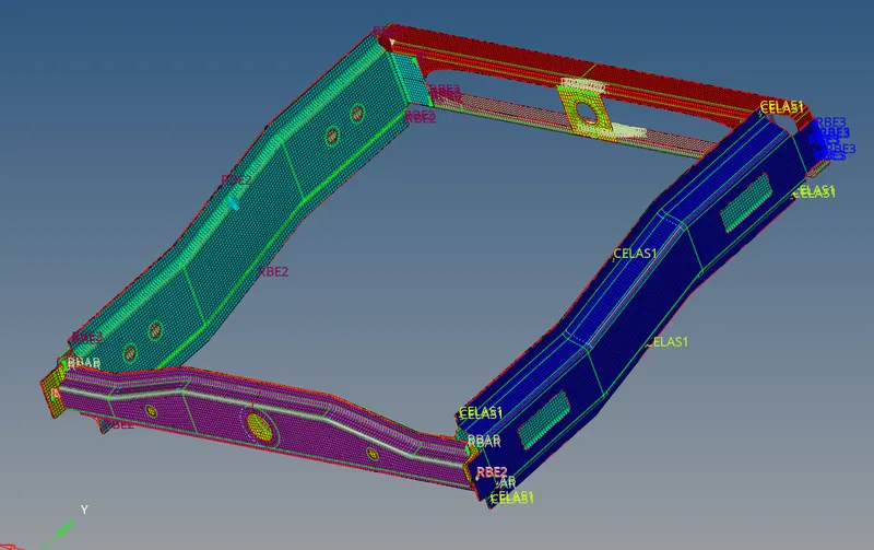
RESULT :
meshed the given components by the given quality criterias.also Created connectors and attached the various parts of the given model.