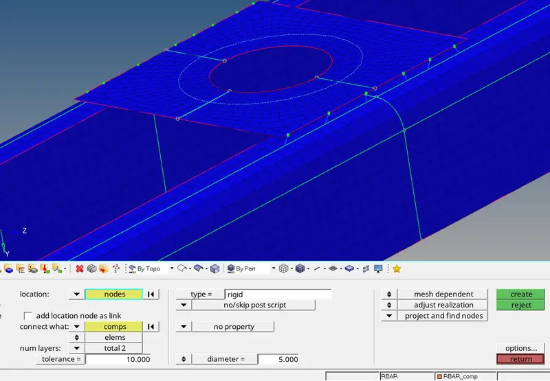
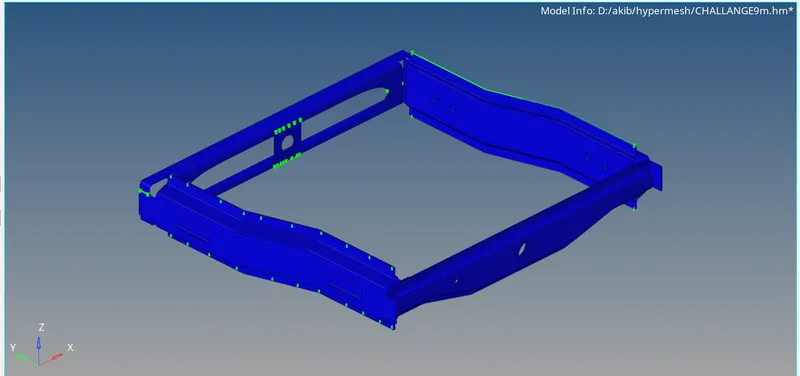
Week 9-Creation of 1D Connectors Challenge
MLDULE 1
Create connector and Attach the various parts of the given model
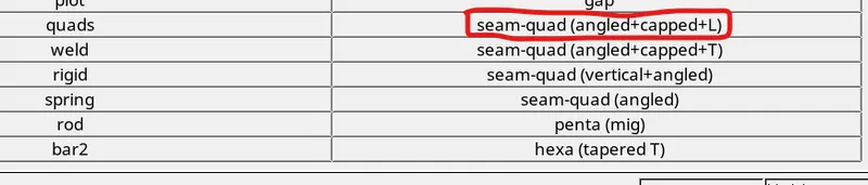
1. Right_Rail_2 & Front_truss_1:- Seam-Quad(angled+capped+L)
2. Left_Rail_2 & Front_truss_1:- Quad elements
3. Front_truss_2, Front_truss_1 & Right_Rail_1:- Spot weld with 2 Layers and 5 mm Diameter
4. Front_truss_2, Front_truss_1 & Left_Rail_1:- Hexa (Adhesive)
5. Rear_truss_2 & Right_Rail_2:- Bolt Connector
6. Rear_truss_2 & Left_Rail_2:- Bolt Connector
7. Right_Rail_1 & Right_Rail_2:- Spot-weld with Rigid Elements
8. Left_Rail_1 & Left_Rail_2:- Spot-weld with Spring Elements
9. Rest all the component left Join them with suitable connectors
Target Element size - 5 Units
|
S.N |
Quality Criteria |
Value |
|
1 |
Aspect Ratio |
5 |
|
2 |
Skewness |
45 |
|
3 |
Warping |
15 |
|
4 |
Taper |
0.5 |
|
5 |
Min. Length |
2 Units |
|
6 |
Max. Length |
8 Units |
|
7 |
Min angle Quad |
45 |
|
8 |
Max angle Quad |
135 |
|
9 |
Min angle Tria |
30 |
|
10 |
Max angle Tria |
110 |
|
10 |
Tria % |
15 |
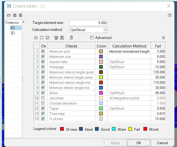
from the above given quality criteria parameters we are going to perform 2D meshing to all the componentes
process to do 2D mesh
click on f12 from the key board
from the status bar click on preference >select the criteria file setting >set the above quality parameters
component 1 (Front truss 1)
press on F12 from keyboard >select the surface >set element size =5>mesh type quard >click on mesh

component 2 (Front truss 2)
press on F12 from keyboard >select the surface >set element size =5>mesh type quard >click on mesh

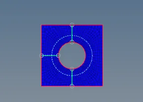
component 3 (reinf_plate)
press on F12 from keyboard >select the surface >set element size =5>mesh type quard >click on mesh
component 4 (right rail_1)
press on F12 from keyboard >select the surface >set element size =5>mesh type quard >click on mesh
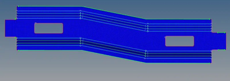
component 5 (right rail_2)
press on F12 from keyboard >select the surface >set element size =5>mesh type quard >click on mesh
component 6 (left rail_1)
press on F12 from keyboard >select the surface >set element size =5>mesh type quard >click on mesh
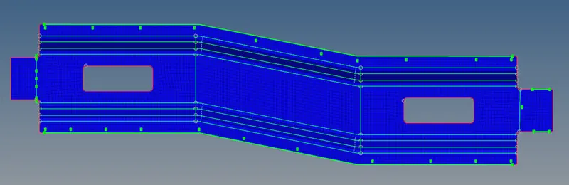
component 7 (left rail_2)
press on F12 from keyboard >select the surface >set element size =5>mesh type quard >click on mesh
component 8(rear truss 1)
press on F12 from keyboard >select the surface >set element size =5>mesh type quard >click on mesh
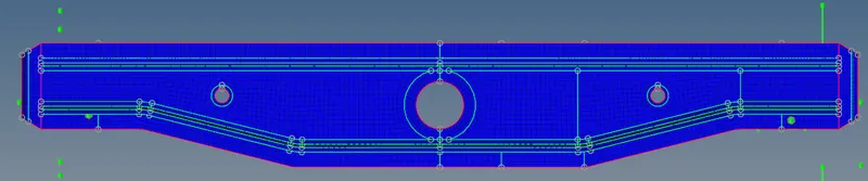
component 9(rear truss 2)
press on F12 from keyboard >select the surface >set element size =5>mesh type quard >click on mesh

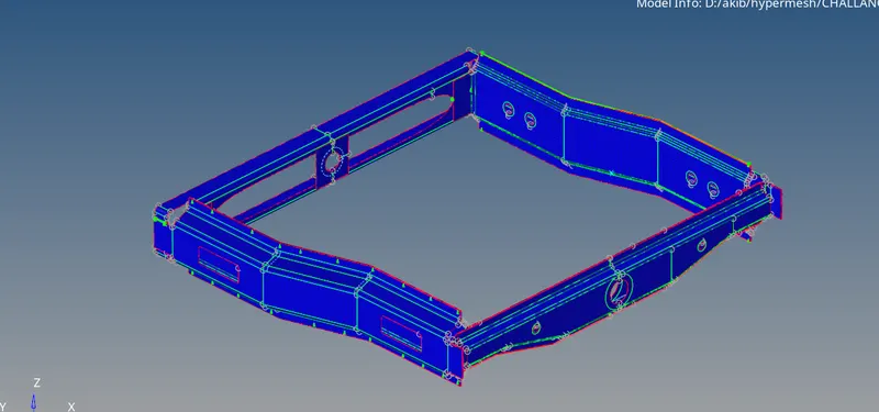
combined components
MODULE 2
Create connector and Attach the various parts of the given model
1: Right_Rail_2 & Front_truss_1:- Seam-Quad(angled+capped+L)
we are going to connect right rail and front truss by using seam weld option
process to connect two components by seam weld
click on 1 D >click on comnnectors >select seam


click on seam >select node by path>set spacing 5>type (seam quard [angled+capped+L)>set weld angle=60 and Cap angle=45>runoff angle =10
now select the option (connect what )>click on comp1 and then cick on comp 2
now hit create

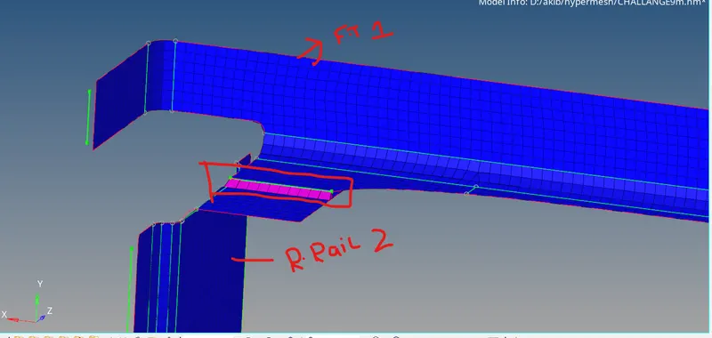
the weld joint has been created below is the image
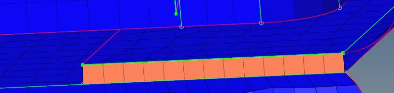
Left_Rail_2 & Front_truss_1:- Quad elements
click on 1 D >click on comnnectors >select seam
click on seam >select node by path>set spacing 3>type (quardL)
now select the option (connect what )>click on comp1 and then cick on comp 2
now hit create
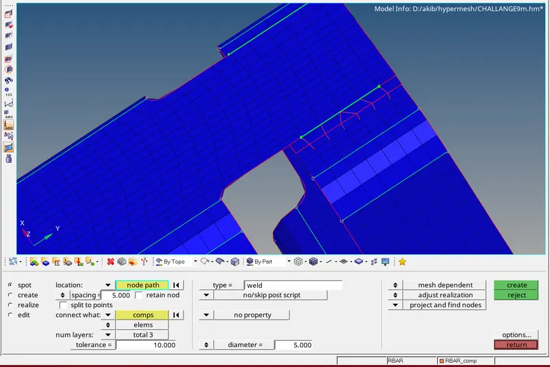
Front_truss_2, Front_truss_1 & Right_Rail_1:- Spot weld with 2 Layers and 5 mm Diameter
click on 1 D >click on comnnectors >select spot
click on spot >select node by path>set spacing 5>type (weld)>set diameter 5 units>set no of layers 2
now select the option (connect what )>click on comp1 and then cick on comp 2
now hit create
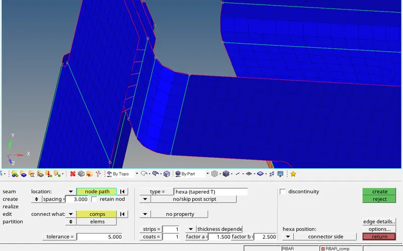
Front_truss_2, Front_truss_1 & Left_Rail_1:- Hexa (Adhesive)
click on 1 D >click on comnnectors >select seam
click on seam >select node by path>set spacing 5>type (hexa tapered T)>set tollerence 10units>set factor a and b as defaulted
now select the option (connect what )>click on comp1 and then cick on comp 2
now hit create
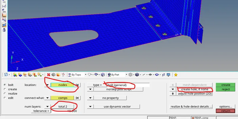
Rear_truss_2 & Right_Rail_2:- Bolt Connector
click on 1 D >click on comnnectors >select bolt
click on bolt >select node >type (bolt general)>set tollerence 10units>set no of layers 2
now select the option (connect what )>click on comp1 and then cick on comp 2>select create hole if none from drop down arrow
now hit create

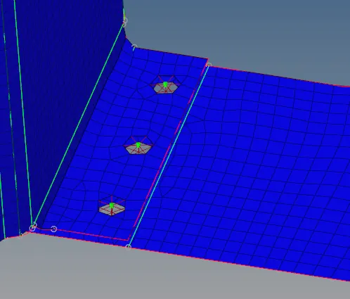
Rear_truss_2 & Left_Rail_2:- Bolt Connector
click on 1 D >click on comnnectors >select bolt
click on bolt >select node >type (bolt general)>set tollerence 10units>set no of layers 2
now select the option (connect what )>click on comp1 and then cick on comp 2>select create hole if none from drop down arrow
now hit create
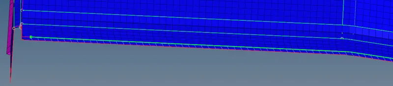
Right_Rail_1 & Right_Rail_2:- Spot-weld with Rigid Elements
click on 1 D >click on comnnectors >select spot
click on spot >select node by path>set spacing 5>type (rigid)>set diameter 5 units>set no of layers 2
now select the option (connect what )>click on comp1 and then cick on comp 2
now hit create
Left_Rail_1 & Left_Rail_2:- Spot-weld with Spring Elements
click on 1 D >click on comnnectors >select spot
click on spot >select node by path>set spacing 5>type (spring)>set diameter 5 units>set no of layers 2
now select the option (connect what )>click on comp1 and then cick on comp 2
now hit create

join reinf plate with front truss 1 front truss 2 (spot rigid)
click on 1 D >click on comnnectors >select spot
click on spot >select node by path>set spacing 5>type (rigid)>set diameter 5 units>set no of layers 2
now select the option (connect what )>click on comp1 and then cick on comp 2
now hit create