Week - 4
Implement control logic of a “washing machine” using Stateflow as per the given sequence:
If the power supply is available, the system gets activated
If the Water supply is not available, stop the process & indicate through LED
Soaking time should be 200s followed by Washing time of 100s.
Then rinsing happens for the next 20s & dryer runs for 50s.
WASHING MACHINE
A washing machine is a machine that washs dirty cloths. It contains a barrl into which the clothes are placed. This barrel is filled with water and then rotated very quickly to make the water remove dirt from the clothes. Most washing machines are made so that detergent(liquid or powder) can be put into the machine. These can help make the clothes cleaner.
SEMI AUTOMATIC WASHING MACHINE
Semi-automatic washing machines have separate sections for Dryer and Washer. These washing machines are often termed as semi-manual as here you have to manually put clothes into washer tub, put water & detergent according to your laundry size, and once washing is finished, you again have to manually put washed clothes for drying in dryer section. These are mostly cheaper machines.
FULLY AUTOMATIC WASHING MACHINE
Fully-automatic washing machines are easier to use. They have only one section for washing and for spin-drying. Once you put clothes in a fully-automatic washing machine, it automatically takes required quantity of water, detergent and just with one click provided your washed & dry clothes.
STATEFLOW
Stateflow provides a graphical language that includes state transition diagrams, flow charts, state transition tables, and truth tables. You can use Stateflow to describe how MATLAB algorithms and Simulink models react to input signals, events, and time-based conditions.
CONTROL LOGIC
Control logic is the part of a controller that defines how a reactive system responds to events or conditional changes. Applications for control logic include
procedure
1 open the chat from the Simulink library inside this block use state block for power supply water supply, soak,washing, rinsing, dryer, and end /finishing block
the following conditions that we have followed in this model
if the water supply is off and the power supply is on the system gets activated up to where the machine needs water for washing, once the system recognizes there is no availability of water the system gets deactivated over their
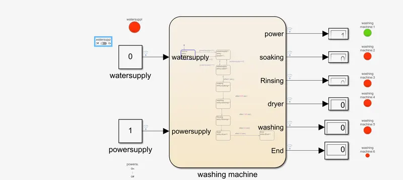
from the above snape its clear that the process has been stopped at the first power state block
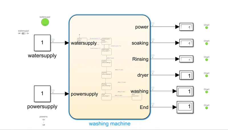
IF both water and power supply is available the system gets activated and runs efficiently throughout the whole process and the process stops at the end block
Make a Simulink chart for the “Gear shift” logic as per below conditions:
Speed Range(kmph) Gear
0 to 15 1
16 to 25 2
26 to 40 3
41 to 60 4
Above 61 5
Give speed input while the simulation is running & display the gear number.
in this gear mechanism model, we are going to use the slider block for the input speed, a lamp that is used as an ignition switch, a speedometer that is used to measure the speed at the output, and a display and this block will indicate the gear no
neutral gear ,speed =0
gear 1 the speed is ranging from 0 to 15km/h the below chart shows the input speed and gear 1 occurs in the output display
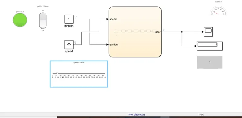
for gear 2 speed greater than 15
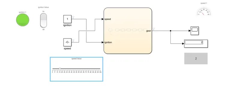
for gear 3:
hear the speed is greater than 25
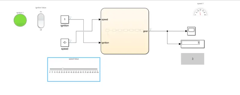
similarly for gear 4 and gear 5: when the speed is >40 the gear is shifted to 4 gear and when the speed reaches above 60km/h it enters into gear no 5
output results