Week 9-Creation of 1D Connectors Challenge
Aim: To mesh the given geometry and create 1D connectors at desired location using Hypermesh.
As per below mentioned Element Quality-
Target Element Size-5 Units
| S. No. | Quality Criteria | Value |
| 1. | Aspect Ratio | 5 |
| 2. | Skewness | 45 |
| 3. | Warping | 15 |
| 4. | Taper | 0.5 |
| 5. | Min. Length | 2 Units |
| 6. | Max. Length | 8 Units |
| 7. | Min. Angle Quad | 45 |
| 8. | Max. Angle Quad | 135 |
| 9. | Min. Angle Tria | 30 |
| 10. | Max. Angle Tria | 110 |
| 11. | Tria % | 15 |
Procedure:
Setting up model
- Importing the geometry into the hypermesh workspace.
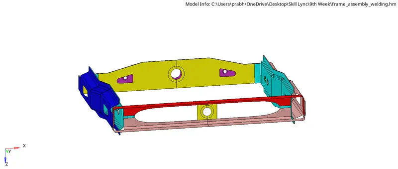
- All the components are seperated and meshed.
- If required, the component can be cleaned for topological errors and defeatured using manual or auto clean upmethod.
2D Surface Meshing & Mesh Refinement:
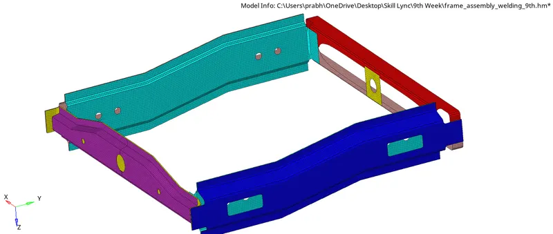
- To generate a mesh over each component we will go to 2D then Automesh then selecting the surface as displayed and setting up target element length to 5 and specifing the mesh type and order then meshing the component.
- However to achive a perfect mesh without quality errors the component is sectioned into different surfaces using surface trim option and meshed separately.
Assigning property card:
- A Single property and material card is added for every component.
- Assuming every component has the identical thickness and material, a single card is added to each.
- To Create material card we will right click on model tab then create material name it as steel.
- Then the necessary material values like poissions ratio, youngs modulus etc are specified.
- The thickness of the component is also specified in the property card itself.
1D Connections:
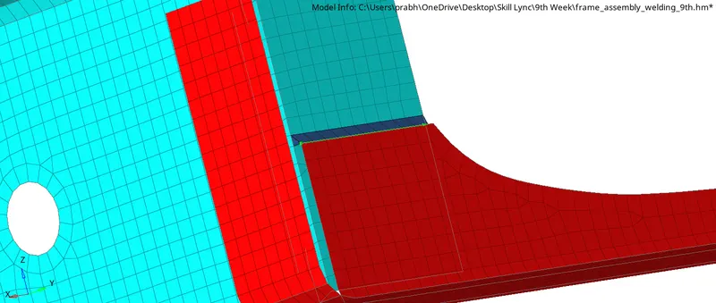
1. Seam-Quad (Angled +Capped+L)
For: Right_Rail_2 & Front_Truss_1
- To create a seam weld we will go to 3D then connectors then seam.
- Then we will be selecting the nodes (by path) on one of the component.
- Put tolerance specify the search distance (10MM)
- Select the two components and keepthe imprint check on.
- Weld type is set as Seam-Quad (Angled+Capped+L)
- The Weld angle can be altered but an angle of 60 or45 is widely prefered based on alignment of the two components.
- The spacing is set as 5mm, spacing defines the distance between the two adjecent weld elements.
2.Seam-Quad elements
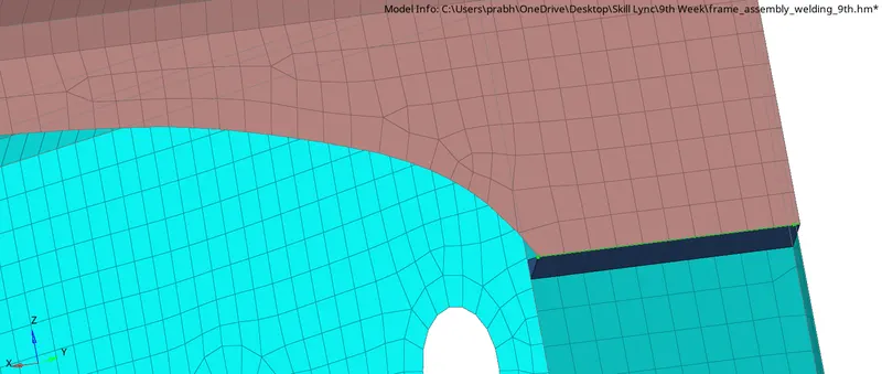
For:Left_Rail_2 & Front_truss_1
- To create a seam weld we will again go to 3D then connectors then seam.
- Then selecting the nodes by path on one of the components
- we will put tolerance of 10mm.
- Then selecting the two components and keep the imprint check on.
- Weld type is set as quad and the spacing that is distance between the two adjecent weld elements is kept as 5 mm.
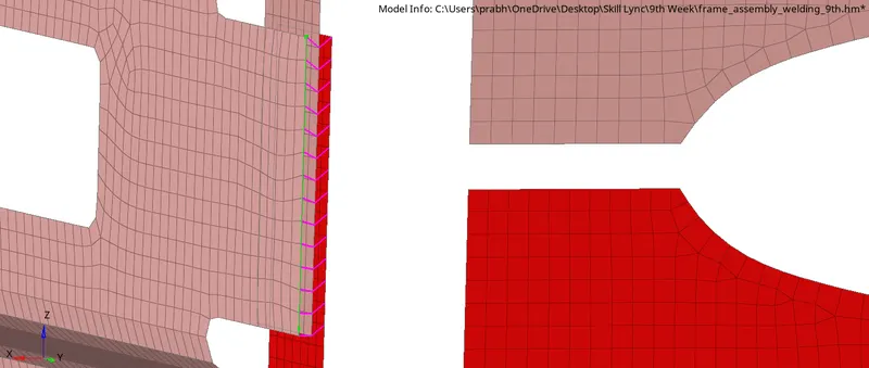
3. Spot weld with 3 Layers and 5mm Diameter
Front_truss_2,Front_Truss_1 & Right_Rail_1
- To Create a spot weld we will go to 2D then connectors then spot then going to type as weld.
- Select all the required nodes where the location of the spot weld has to be placed and also keeping the tolerance as 10 and spacing as 5mm.
- Then select all the 3 components.
- specify the diameter as 5mm and number of layer as 3.
4.Hexa (Adhesive)
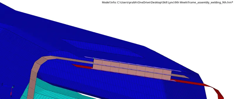
For: Front_truss_2,Front_truss_1 & Left_Rail_1
- To create this we will go to option 3D then connectors then seam.
- Select the nodes (by path) on one of the component.
- And keeping the tolerance as 10mm then selecting the two components and keeping the imprint check on. then set weld type as hexa(adhesive) under the weld type category.
- The strips and coats of the weld can be altered.In this perticular case the strip is set as 2 and a single coating is specified.
5. Bolt Connector
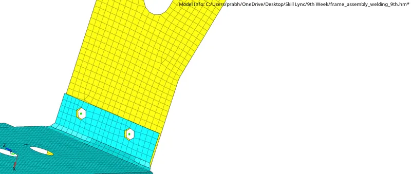
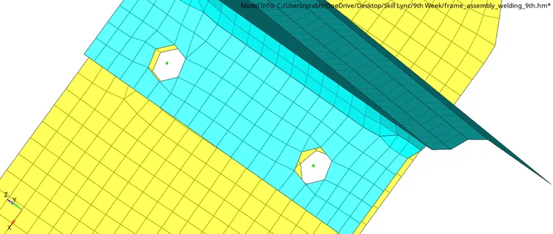
For: Rear_truss_2 & Right_Rail_2
- To create a bolt connector we will go for 3D then we will go to connector then selecting bolt.
- We will select two single nodes on the surface at thecertain distance in one component since two bolt connectors are being realised.
- Select the two components which has to be fixed by the bolt.
- Select the option to create a hole to define the bolt as a physical element one thing to noted is that it will modify and alter the neighbouring mesh.
6. For: Rear_truss_2& Left_Rail_2
7. Spot-Weld with Rigid Elements
For:Right_Rail_1 & Right_Rail_2
- It is similar operation to spot weld creation, this spot weld is created using rigids instead of weld.
- To create a spot weld we will go to connectors then spot then selecting type as rigids.
- Selecting the required nodes where the location of the spot weld has to be placed.
- Then selecting both the component.
- Specify the diameter and number of layer.
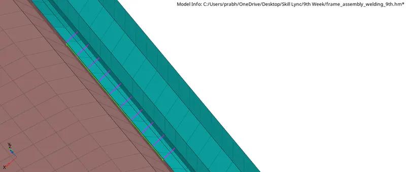
8. Spot Weld with Spring Elements
For: Left_Rail_1 & Left_Rail_2
- It is also similar operation as of the previous one, this spot weld created using spring instead of weld.
- To create we will go to connector then spot then selecting the type as spring.
- Now will select all the required nodes.
- And also selecting both components on which this operation needs to be carried out.
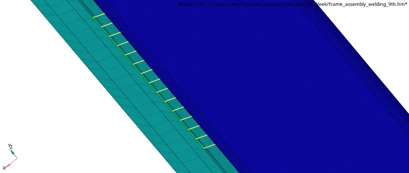
9. For other Components
- In case of shell component with the hole, a hex (adhesive) connection is made.
- To create this we will selecting the connector then seam then selecting the nodes on one component and specifying the tolerance as 50mm then selecting the two components.
- checking the weld type as hexa (adhesive) under weld type category.
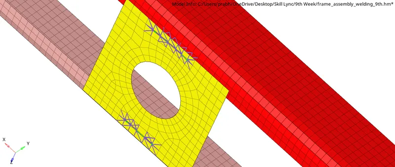
- And for remaing components we will go for bolt connectors and spot weld.
Conclusion:
Here we understand how to provide different types of connectors on the components.