Week 9-Creation of 1D Connectors Challenge
Procedure:
To start with meshing on any component we have to go through several preliminary stages, which includes geometry cleanup, mid surface extraction , mid surface clean up and set up mesh parameters.
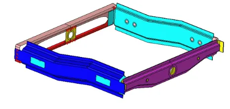
So, in hyper mesh, we need to first check for solid in the feometry, after import the model and to delete the solied we will use the universal delete option and change the selection types to solid and select and delete. but when we tried solied in our model it selected nothing that means solid were not present in our model.
Now we need to check for nay geometry errors. this we can check by switching to wireframe model and check for any red lines mean free edges. it shows geometry is not stitched properly, because of these errors we may need to create new surface or stich 2 edges together and many more possibilities are there for our model, we found no errors.
next, we extract the mid-surface but here we need not do it as ir a mid surface provided to us now we need to check for mid-surface quality and it was in a good state so, our next step for model will be defeaturing as per provide quality criteria but as this model is very straightforward, we need not defeature any region and can start meshing on it,
Now we can start with meshing area always atart with feature capturing first and from the produce further this way we started meshing by usinng option 2D auto mesh-select surface - define mesh parameter asked - and mesh. handling meshing in the hyper mesh is very easy as we can change the number of node we require on edges and generally we keep it the sam on opposite edges to avoid tria formations.
Tips to have good mesh:
. keep number of nodes same on opposite edge of an area
. prefer quad element over tira
. no trial should be there on free edges
. No opposite tira should be there in model
. Rotating quad should nopot be there we can have tira in place quads if that area demands it
. Mesh flow should be check which mean meshing should not be in a zigzag way, it should be following straight-line paths .in curve region we can have flow along the curve
This way we did meshing for this model. also meshing should be goos because if the mesh is not proper at the connection location, then it is seen that it may lead to unrealization of connection.
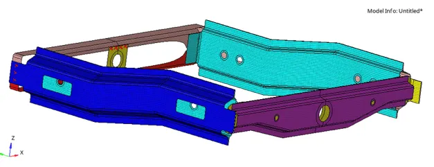
Now after successful completion of meshing we need to provide connection at all relevent location with specifi connection types as asked so to start with connection , we need go to 1D panel and there we go to connectors. under this, we will have majorly all types of connections.
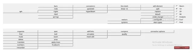
And if we want to create a beam or bar to have a specific degree of freedom at a location then we can create a cross-section using a hyper beam. generally , connection types depends on several factor like:
. component material properties that are being connected
.degree of freedom we required at that location
.quality of connection we require at that location, how weak it should be, or how strong it should be, and many more factor plays role in deciding connection type
Now to start connection we should know thae meaning of connection type
seam welding is a welding technique in which the two similar or dissmilier metals are connected by supply an electric current and in this process a nugget takes place. mostly these nuggets are formed in the form in butt or overlapping welding component. nuggets are nothing but small pools of metal which are formed at a loaction with electric resistance. seam welding in one of the types of resistance welding.
spot weld is a process to join various sheet metal product through a process in which contacting metal surface point are join by the heat obatined from resistance to electric current, at a number of separete points.
A bolts connection can be used for end connectoors in tension and compression member. they can be also hold down column best on position and as a seperate for purlins and beams in foundations.
The adhesive connection is a connection when two component are bounded together using an adhesive.
Now we will start with seam weld so for this we will go to 1D-connectors-seam.
we need to select the nodes along which we need connection then we ned to pass specing values which should be same as target elemet length ideall also we can measure the distance between nodes and give the same value. then we tick retain nodes to retain the position of nodes while creating and realizing the connector and then we select componenet to be welede then we give tolerance value which is very important as if we pass incrrect tolerance value our connetion won't realize tolerance value depends on the gap between two componenet, all this definition decide weld location.
then we need to be select the types of selctet the types of seam weld we require. and define value for weld angle, cap angle, and runoff angle if necessary. all this define weld properties.
then the last thing we decide is wheather iwe want to skip important or imprint meaning wheather we just need a connection to be made between duplicates element at the same location and them duplicate element and do connection manually at desired nodes or directly create a connection they we actualy we acn keep or exiting mesh the position because while connects
now to know our conncetion is realize iour not be can check by connection color. if it is green in color then it is realize if it is yellow, it is unrealize, and if it is red then the connection failed. correct parameter definition never leads to yellow and red color keeping all these factor in mid we create seam (angel + capped + L) at the asked location.
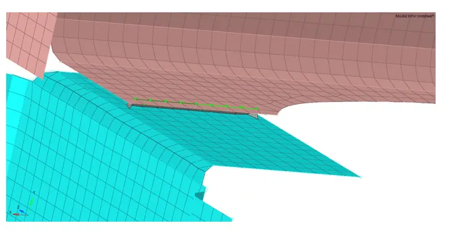
Now as we see here we have a connection with good mesh flow but actually what happends mesh was disturbed after connection realization and then we reworked on mesh later.
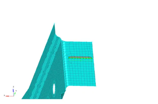
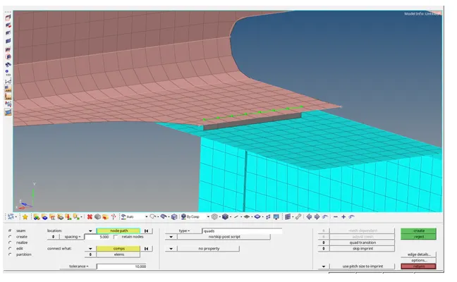
Now we will be creating a quad types of connection which is also present in seam welds only. now the parameter as define in seam angle capped L same paramertre were asked for quad also the difference was we, don't have a requirement here to define wled angle, cap angle, and runoff angle as the quad formation will happen here.
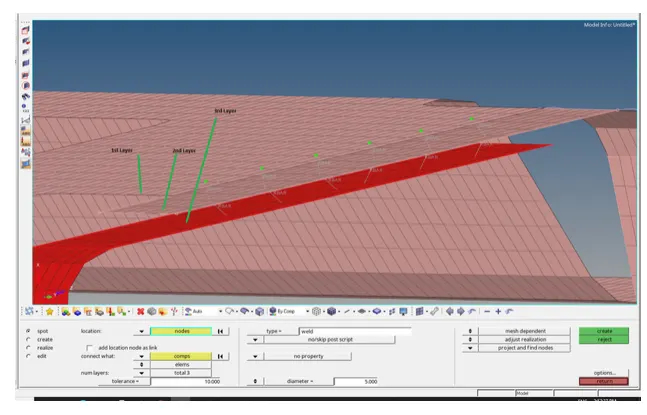
Next , we need to create a spot weld of 3 layers and 5mm diameter between front_truss_2, front_truss_1 and Right_rail_1. for this we need to go to 1D -connectors -spot -pass relevant parameter and realize.
Next, we need to create hexa adhesive connection between front_truss_2,front_truss_1 and left_rail_1.for this we need go to 1D-connections_seam_and select types as gexa adhesive _ pass relevants parameter _realize.
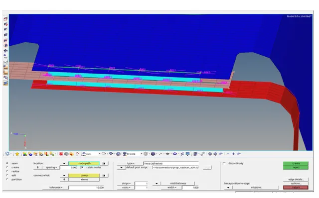
Here strips and coats divide the hexa element horizontally and vertically which provides us added advantage to define different properties to each layer of element to have multiple degree of freedom along connection only.
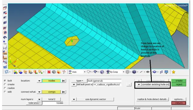
Next we need to do bolts connection at 2 location i.e. Rear_truss_2 and Right_rail_2 and reartruss_2 and left_rail_2. for this we need to go to 1D - connnector - bolt - pass relevent parameter and realize.
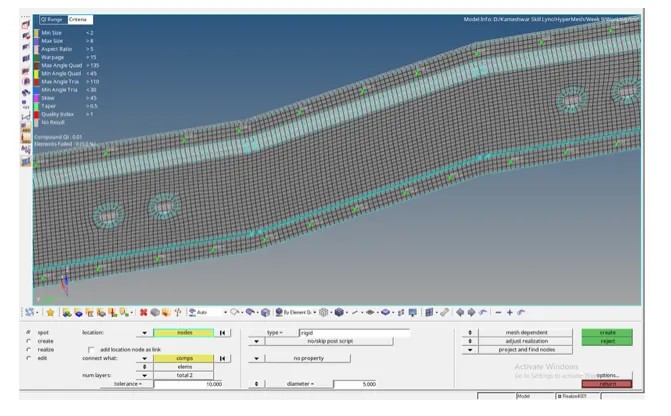
Next, we need to do to spot-weld with Rigit element between Right_Rail_1 and Right_Rail_2. to do this we will go to to 1D - connectors - spot - change types to rigit- pass relevant parameter and realize.
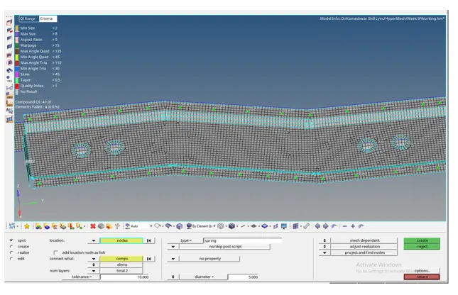
Next, we need to go to a spot-weld with spring element between left_rail_1 and Left_rail_2. to do this we will go to to 1D - connector - spot - change type to spring- pass relevent parameter and realize.
And at rest location where we feel the connection is required, we did spot weld connection as it looked like spot connection is good for those locations.
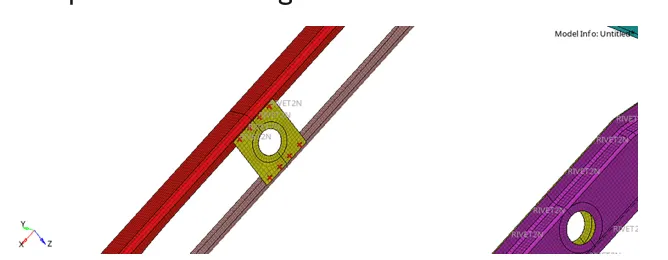
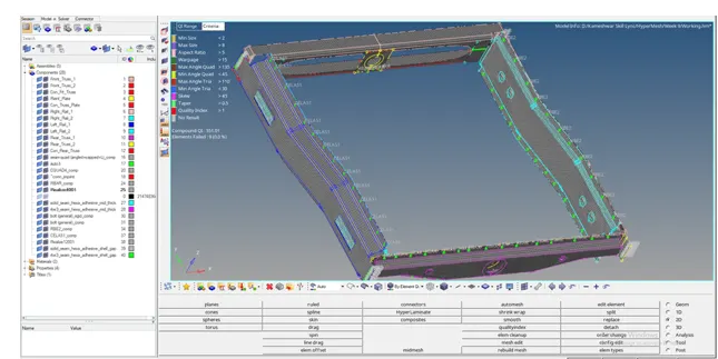
This is to be notecd that remash was done after successful connection realization wherever needed.
Full model with all successful connections.
Conclusion:
In this challenge, we learned about how to do 1D connection at various locations how to successful realize them. also, we learned a little when to use which types of connection and what all factors decide the selection of connector type. also we learned about which all connectors we have.