Week 9-Creation of 1D Connectors Challenge
Aim: Mesh the given geometry and provide the necessary connections.
Procedure:
Step 1: Create a 2D mesh for the mid-surface
Step 2: Check for the quality criteria
Step 3: Create the necessary connections and make sure the connections are realized
Step 4: Check and clear the quality criteria if any
Theory:
The connectors are the representations of physical connections like weld, seam weld, spot weld, springs, bush, etc between the two components.
The connectors are present in all domains 1D, 2D, 3D.
The connectors are used to link the FE entities.
The connectors are realized into FE representations to make sure the connection is proper, represented by green colour.
Given conditions:
Target Element size - 5 Units
|
S.N |
Quality Criteria |
Value |
|
1 |
Aspect Ratio |
5 |
|
2 |
Skewness |
45 |
|
3 |
Warping |
15 |
|
4 |
Taper |
0.5 |
|
5 |
Min. Length |
2 Units |
|
6 |
Max. Length |
8 Units |
|
7 |
Min angle Quad |
45 |
|
8 |
Max angle Quad |
135 |
|
9 |
Min angle Tria |
30 |
|
10 |
Max angle Tria |
110 |
|
11 |
Tria % |
15 |
Create connector and Attach the various parts of the given model
1. Right_Rail_2 & Front_truss_1:- Seam-Quad(angled+capped+L)
2. Left_Rail_2 & Front_truss_1:- Quad elements
3. Front_truss_2, Front_truss_1 & Right_Rail_1:- Spot weld with 2 Layers and 5 mm Diameter
4. Front_truss_2, Front_truss_1 & Left_Rail_1:- Hexa (Adhesive)
5. Rear_truss_2 & Right_Rail_2:- Bolt Connector
6. Rear_truss_2 & Left_Rail_2:- Bolt Connector
7. Right_Rail_1 & Right_Rail_2:- Spot-weld with Rigid Elements
8. Left_Rail_1 & Left_Rail_2:- Spot-weld with Spring Elements
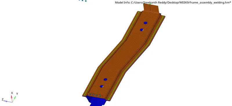
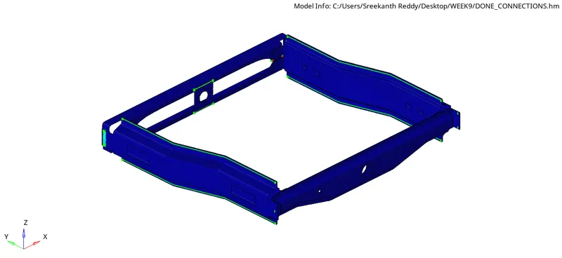
9. Rest all the component left Join them with suitable connectors
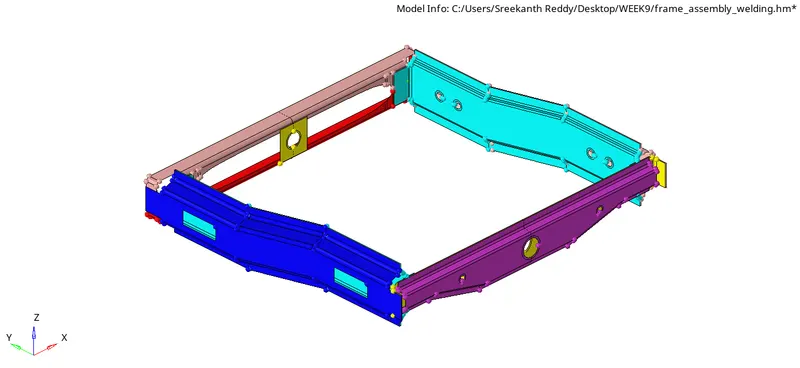
Import the given CAD model:
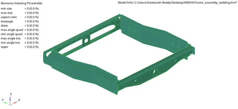
Mesh the components to the given quality criteria:
Connections:
1. Connect the Right_Rail_2 & Front_truss_1 with the Seam-Quad(angled+capped+L)
Isolate the respective parts.

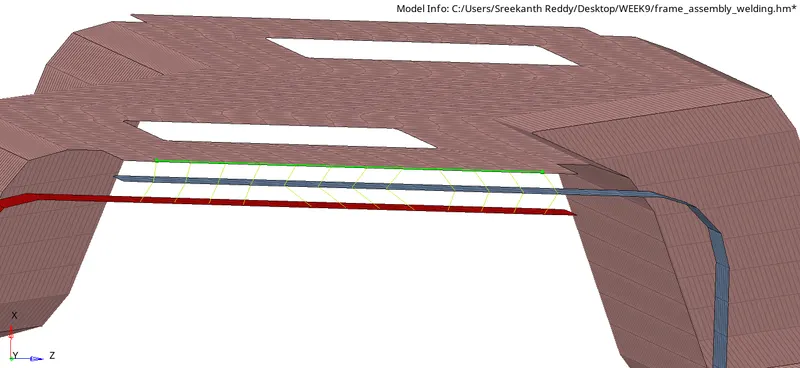
Go to 2D >>> Connectors >>> Seam weld >>> Seam >>> In location select either lines or node path >>> Provide the Spacing, which represents the distance between the two nodes >>> Enable retain node which doesn't change the placement of nodes even after the creation of connection >>> Select the components >>> provide the tolerance arbitrarily which represents the distance between the two connecting components.
Make sure the type of weld to be "angled+capped+L"
There are additional options to control the mesh and connections.
Mesh dependent and mesh independent
In mesh dependent, we can control how elements are to be created either to project and find nodes or the closest nodes. we can also adjust the mesh or adjust the realization.
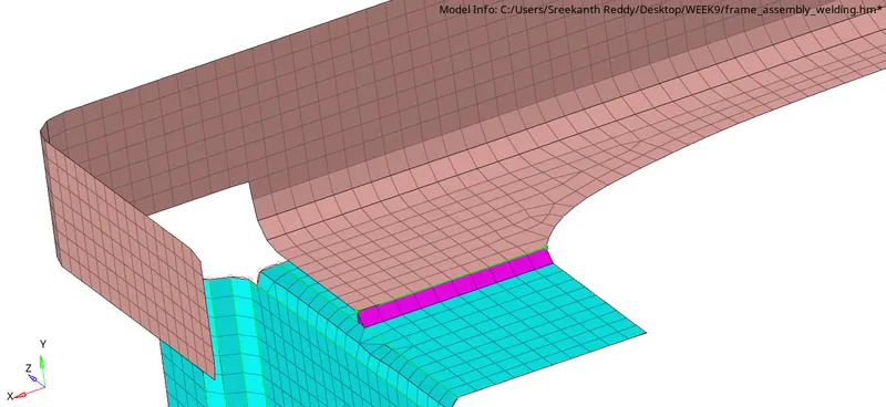
We can see the mesh is distorted and the flow should be controlled by re-meshing the area.
The green line is representing that the connection is properly realized.
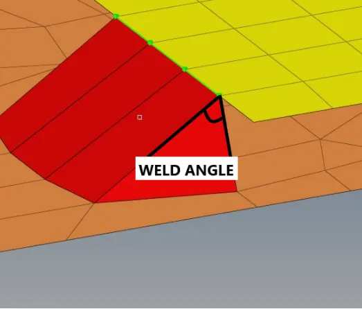
The wedge angle:
The angle between the normal projection of nodes and slant length of the weld. It is defined between 0-90 degrees
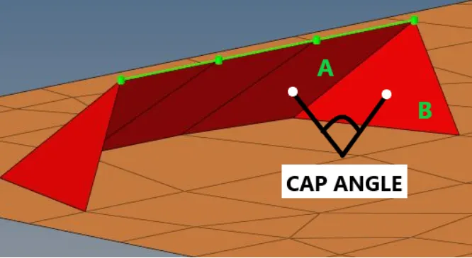
Cap angle:
The angle between A & B.
If the seam weld angle is defined as 45 degrees, the cap angle is recommended to be less than 10 degrees.
If the seam weld angle is defined as greater than 45 degrees, the cap angle is recommended to be greater than 75 degrees.
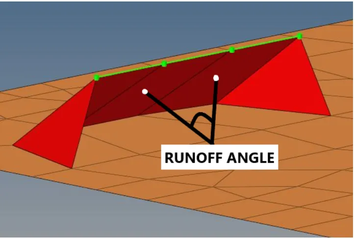
Runoff angle:
The angle between the normal of the first slant weld element and its adjacent elements, defined between 0-10 degrees.
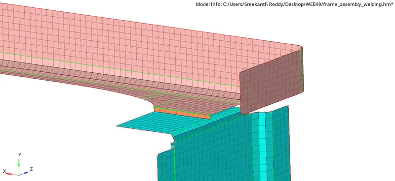
2. Connect the Left_Rail_2 & Front_truss_1:- Quad elements
Similarly, the connections are made by changing the type of weld.
Select the type of seam weld as Quad.
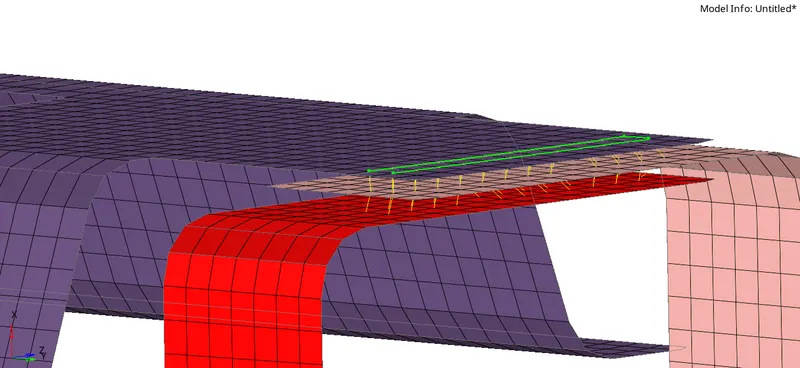
3. Connect the Front_truss_2, Front_truss_1 & Right_Rail_1:- Spot weld with 2 Layers and 5 mm Diameter
The layers are selected according to the number of components to be connected.
In this case, 3 components are connected so the layers should be 2.
The below figure represents the spot weld
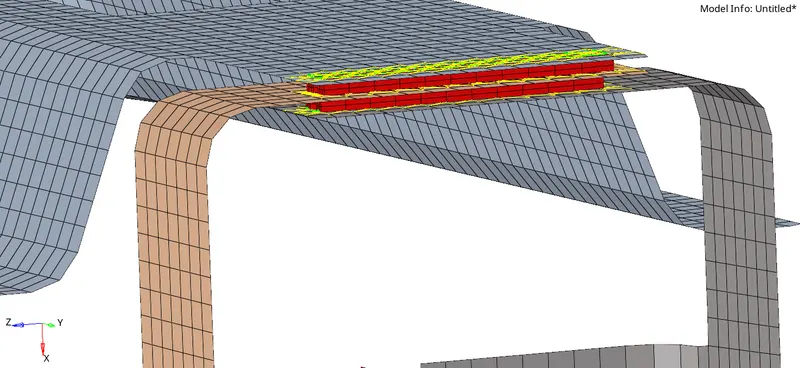
4. Connect the Front_truss_2, Front_truss_1 & Left_Rail_1:- Hexa (Adhesive)
Seam >>> Type as Hexa adhesive
The below image represents the adhesive weld.
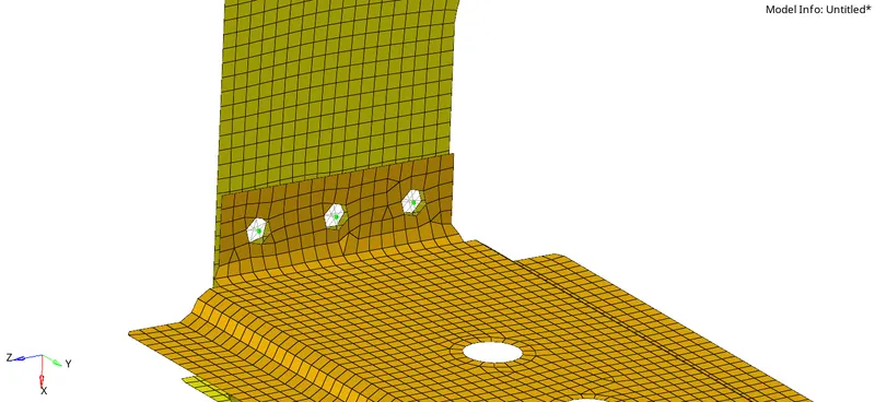
5. Connectors using bolts

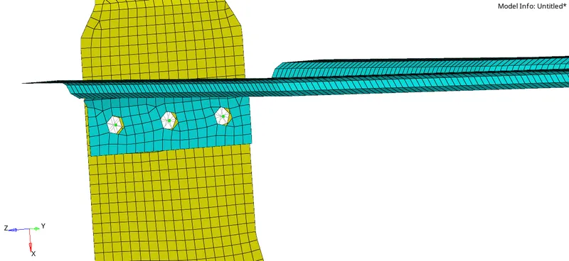
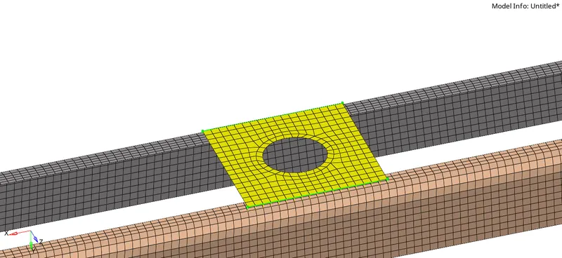
The nodes are to be selected, and the type of bolt required, tolerance are to be selected.
If the holes are not present, We can select to create both hole and bolt connections
If holes are already present we can select to consider the existing hole only.
6. Connectors using bolts
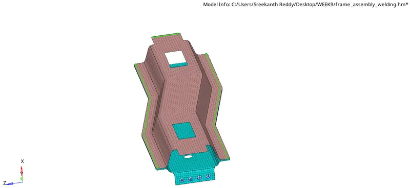
7. Right_Rail_1 & Right_Rail_2:- Spot-weld with Rigid Elements
Go to spot weld >>> Type as rigid elements >>> select nodes by path >>> Create
8. Left_Rail_1 & Left_Rail_2:- Spot-weld with spring Elements
Go to spot weld >>> Type as spring elements >>> select nodes by path >>> Create
9. Join rest all the components left with suitable connectors
Learning Outcomes:
- The types of connections that can be made in Hypermesh.
- How important is the realization in connections
- Understanding the importance of various parameters that are considered while connections are made.