Week - 4 - 2D meshing for Plastic components
Aim: To the given Plastic Bottle Cap model, check for the geometrical errors and take the mid surface by suitable mid surfacing techniques. PID and Thickness assignment is done for all the mid surfaces. Mesh the same with given element Quality criteria.
Procedure:
Step 1: Geometric clean-up of the cad model i.e., Plastic Bottle Cap model.
After importing the cad model, the geometrical errors in the cad model are to be spotted and fixed.
After importing cad model >>>>> Tools >>>>> Check Geometry.
Check Geometry >>>>> Geometry >>>>> enable unchecked faces, collapsed cons, triple cons, needle faces, overlap faces, cracks.
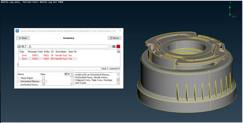
After enabling execute the check geometry.
The errors in the geometry of the model are visible in check list, if geometry is not having any errors after executing it will show 100%.
If any errors are present in model, fix the errors by deleting the unnecessary sharp edges, needle faces. If any triple cons are present release the cons and check if any extra cons or faces are present, If there delete the extra faces or cons. Some triple cons are needed in the geometry where three faces are having connection such as T junction.
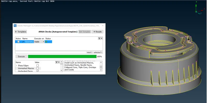
These errors in geometry have to be fixed until 100% clean geometry is obtained.
Step-2: mid-surface extraction.
After geometry clean-up we extract the mid surface to each part of the model.
Create lock views for each part of the model so that we can hide the parts when required.
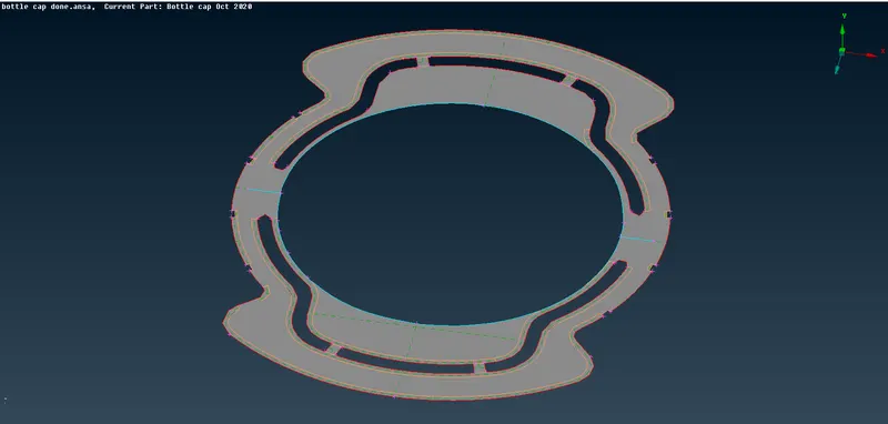
Go to the topo module >>>>> faces >>>>> offset (Offset is ued for uniform thickness plastic faces)
Offset >>>>> Select the faces using left mouse click in entity mode (switch on the hatch option in invisibility bar to select faces easily) and press middle button >>>>> give the offset set value and select the direction in which offset is required.
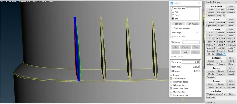
Go to the topo module >>>>> faces >>>>> middle >>>>> multi (Middle multi is used for non-uniform thickness plastic faces)
Middle multi >>>>> select one side of the face(red) >>>>> select opposite side(green) >>>>> select thickness(blue).
The middle of non uniform thickness can be extracted.
Perform the topo after extracting the mid-surface.
Use topo >>> faces >>> extend (To extend the mid surface to another mid surface to maintain connectivity as parent geometry).
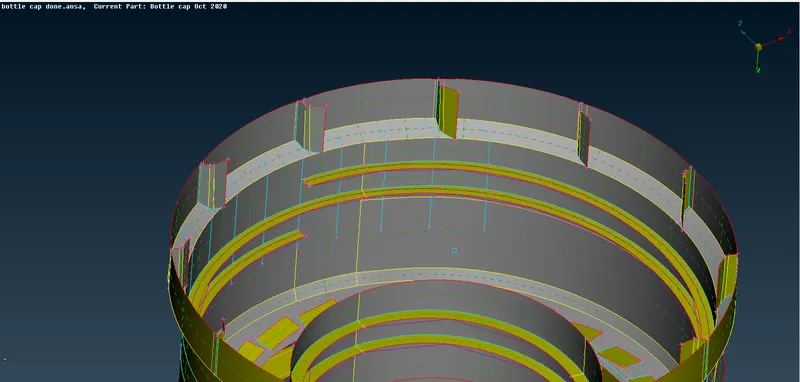
Use Topo >>> faces >>> intersect (To intersect the 2 faces or if needed we can delete the extra part by joining 2faces).
We can also extract mid surface of the part using Feature Area instead of entity, where we can select whole feature/part in one left click of mouse instead of selecting the faces individually.
Create property ID to each mid-surface and assign thickness to it.
For non-uniform thickness features/faces take average values of the thickness. Use edge to parameter if needed to assign two different thickness values to a feature of different PID.
Topo module >>> Faces >>> Set PID >>> Select faces >>> new >>> PSHELL >>> Name the property and assign thickness.
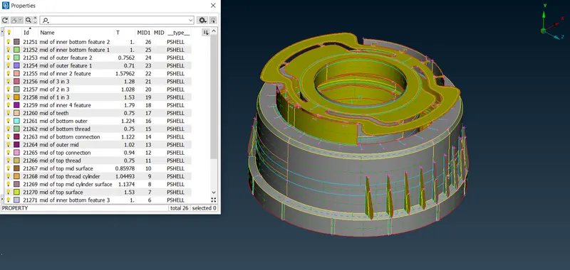
For the features which are of un-even thickness, use middle multi to generate the mid-surface.
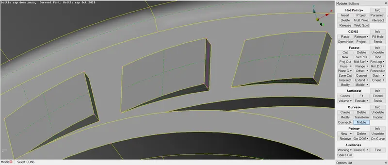
For the teeth feature use (topo module >>> curves >>> middle) to generate middle curve. At the other end, project the con on to mid-surface and create new surface.(topo module >>> faces >>> new >>> cons)
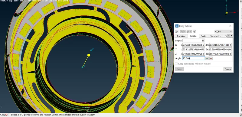
Use transform >>> copy >>> entity >>> rotate, to transform the feature instead of creating individual mid surfaces.
For the thread feature use curves middle at top and bottom to create a middle curve and create a new face using 2 curves and extend the middle surface of the thread to the outer middle face.
Step-3: Mesh creation and Quality check
After extracting the mid-surface >>>>> Mesh the mid surface with the given element Quality criteria.
Utilities >>> Quality criteria >>> Shells >>> select the provided and give values to them >>> Apply.
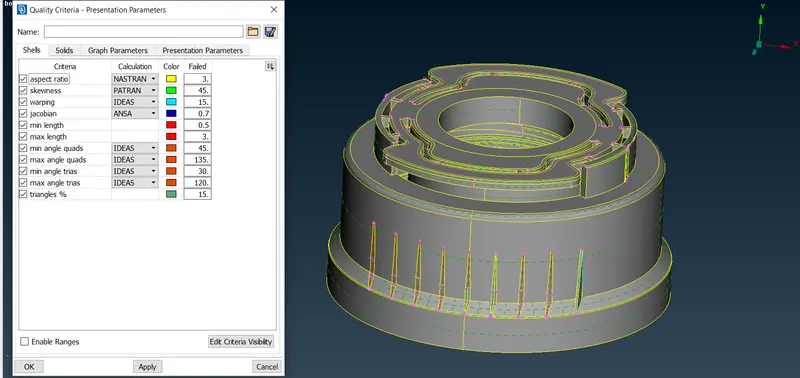
Utilities >>> Quality criteria >>> presentation parameters >>> graphics >>> enable Elements % and detail on demand effect to all details.
Utilities >>> Mesh parameters >>> provide values to target length, minimum length, maximum length >>> Ok.
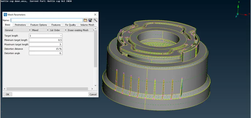
Mesh >>> length >>> perimeter >>> give the value.
Check the length between 2 node using measure tool such that it meets quality. If not met defeature the geometry such that it meets the quality.
Mesh mid surface of each part individually as the model is a complex geometry.
Mesh module >>> mesh generation >>> best mesh >>> select the faces individually in ENT mode or use MACRO AREA to select feature or PID to select a particular property ID.
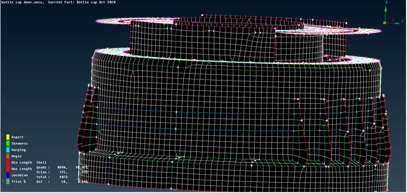
Mesh module >>> shell mesh >>> reconstruct.
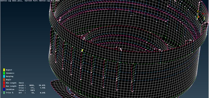
No rotating quads and opposite trias should be present in the model, trias near to free edge or holes or fillets should be eliminated. OFF elements after giving quality criteria must be zero.
By using the paste, split, join tools, we try to remove the tria elements.
We use swap to take trias away from each other.
In this model some off elements near to triple cons are un-avoidable.
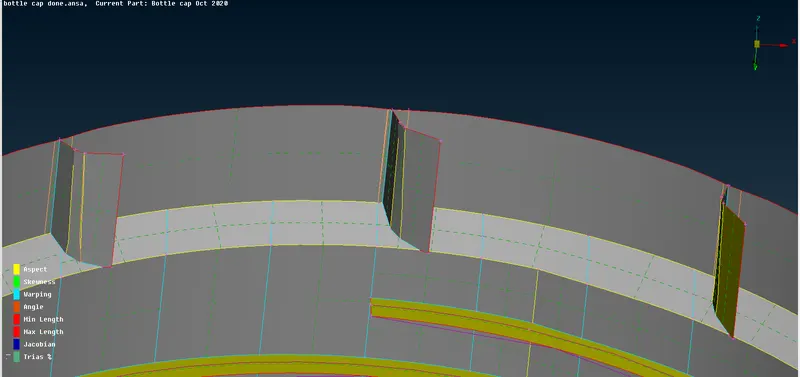
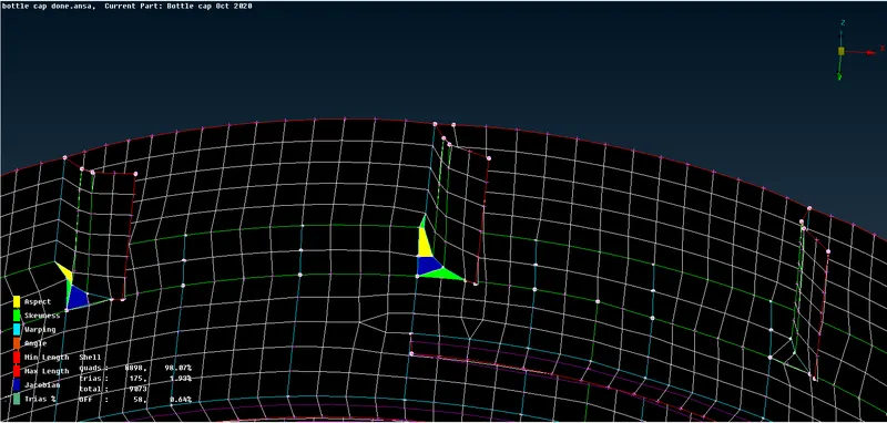
Step 4: Draw shell as solid should be activated.(To compare the meshed model with the parent geometry)
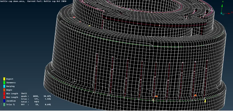
Learning Outcomes:
I have learnt, how to take mid-surface for varying thickness components, mid-surfacing to intricate shape features, how to use curve middle if needed, using extend and intersect the mid surface, creating PID for varying thickness, when to use edge to parameter, significance of draw shell as solid.
Conclusion:
Thus, to the given Plastic Bottle Cap model, geometrical errors are checked and mid surface by suitable mid surfacing techniques are extracted. PID and Thickness assignment is done for all the mid surfaces. Meshed the same with given element Quality criteria and activated draw shell as solid.