Week 3 - 2D meshing for sheet metal
AIM: To clean-up the CAD geometry and mesh the model to the quality requirements which is ready-to-run solver input file.
PROCEDURE:
Step-1: Geometric clean-up of the cad model i.e., hood model.
After importing the cad model, the geometrical errors in the cad model are to be spotted and fixed.
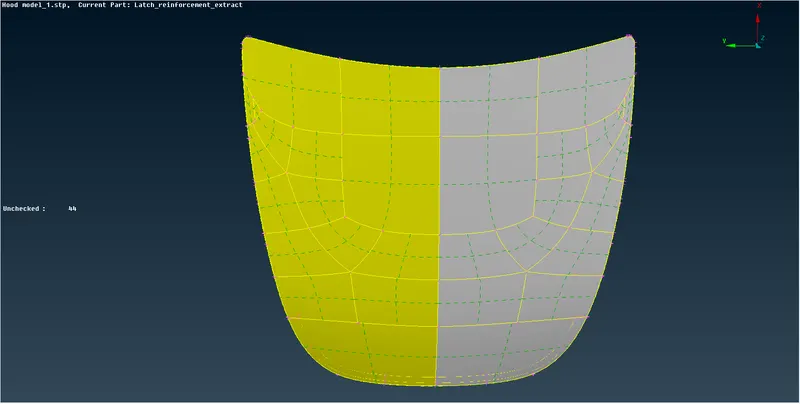
After importing cad model >>>>> Tools >>>>> Check Geometry.
Check Geometry >>>>> Geometry >>>>> enable unchecked faces, collapsed cons, triple cons, needle faces, overlap faces, cracks.
After enabling execute the check geometry.
The errors in the geometry of the model are visible in check list, if geometry is not having any errors after executing it will show 100%.
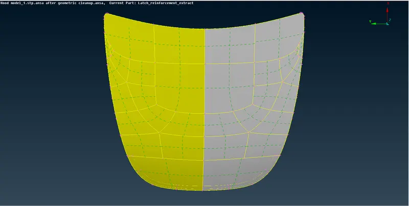
If any errors are present in model (In the model there are 44 unchecked faces), fix the errors by deleting the unnecessary sharp edges, needle faces. If any triple cons are present release the cons and check if any extra cons or faces are present. If there delete the extra faces or cons.
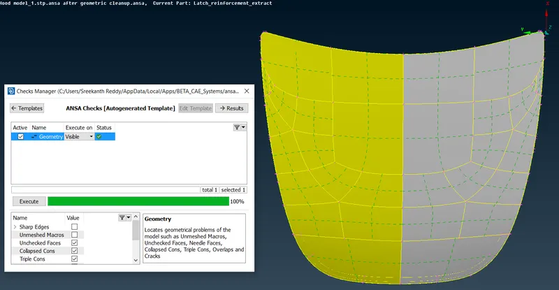
These errors in geometry have to be fixed until 100% clean geometry is obtained.
Step-2: mid-surface extraction.
After geometry clean-up we extract the mid surface to each part of the model (inner panel; outer panel; latch; hinge 1; hinge 2)
Go to the topo module >>>>> faces >>>>> offset
Select the faces using left mouse click in entity mode (switch on the hatch option in invisibility bar to select faces easily) and press middle button >>>>> give the offset set value and select the direction in which offset is required.
Perform the topo after extracting the mid-surface of each part.
We can also extract mid surface of the part using Feature Area instead of entity, where we can select whole feature/part in one left click of mouse instead of selecting the faces individually.
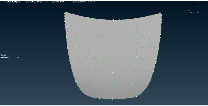
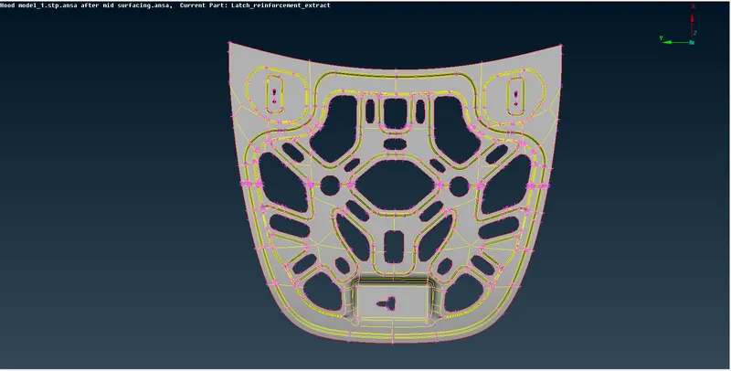
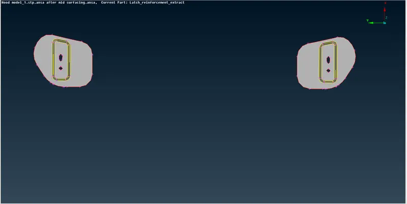
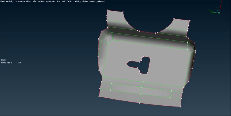
Create lock views for each part of the model so that we can hide the parts when required.
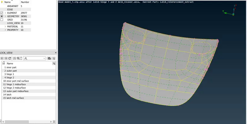
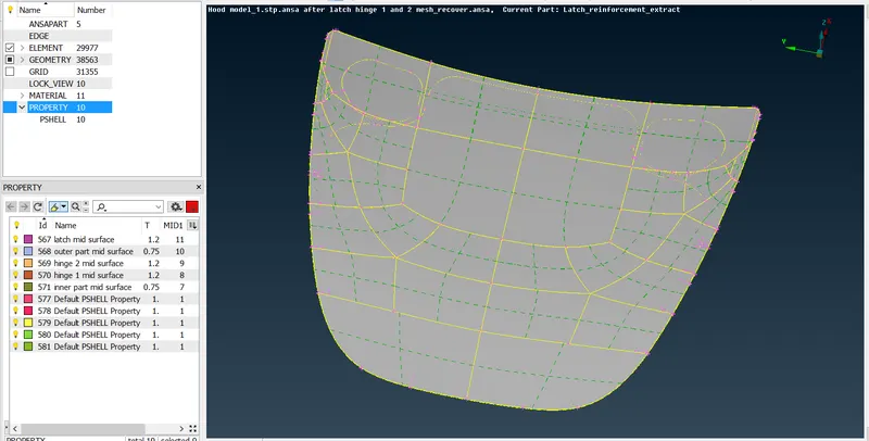
Create property ID to each mid-surface and assign thickness to it.
Topo module >>> Faces >>> Set PID >>> Select faces >>> new >>> PSHELL >>> Name the property and assign thickness.
Step-3: Mesh creation and Quality check
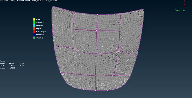
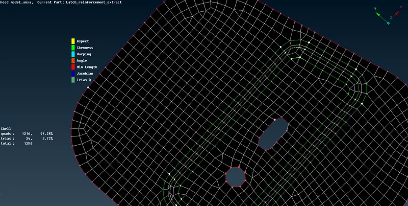
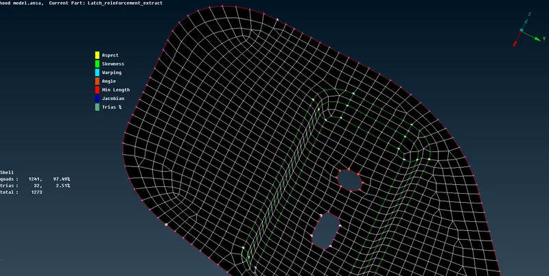
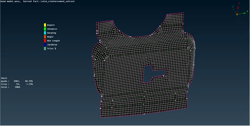
After extracting the mid-surface >>>>> Mesh the mid surface with the given element Quality criteria.
Utilities >>> Quality criteria >>> Shells >>> select the provided and give values to them >>> Apply.
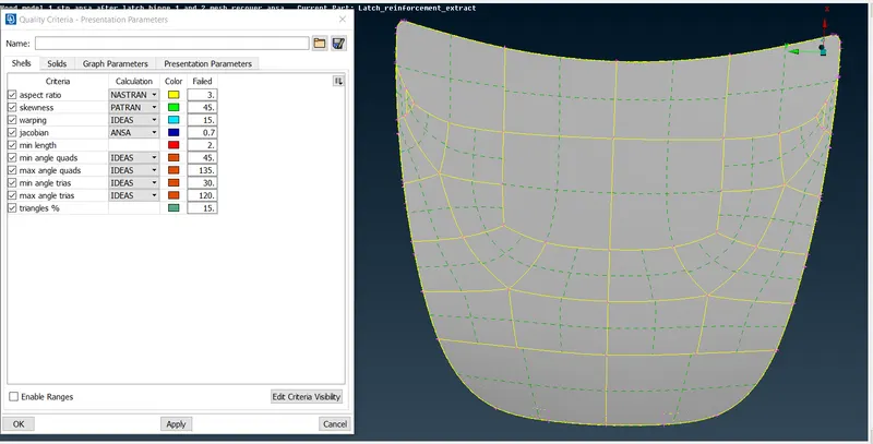
Utilities >>> Quality criteria >>> presentation parameters >>> graphics >>> enable Elements % and detail on demand effect to all details.
Utilities >>> Mesh parameters >>> provide values to target length, minimum length, maximum length >>> Ok.
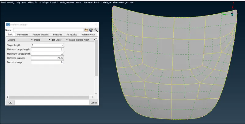
Mesh >>> length >>> perimeter >>> give the value
Check the length between 2 node using measure tool such that it meets quality. If not met, defeature the geometry such that it meets the quality.
Mesh mid surface of each part individually as the model is a complex geometry.
Mesh module >>> mesh generation >>> best mesh >>> select the faces individually in ENT mode or use MACRO AREA to select feature or PID to select a particular property ID.
Mesh module >>> shell mesh >>> reconstruct.
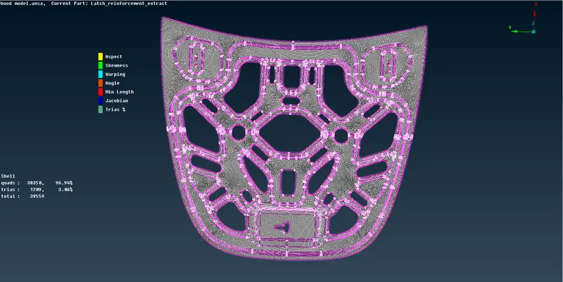
No rotating quads and opposite trias should be present in the model, trias near to free edge or holes or fillets should be eliminated. OFF elements after giving quality criteria must be zero.
By using the paste, split, join tools, we try to remove the trias elements.
We use swap to take trias away from each other.
LEARNING OUTCOMES:
What is ANSA; Phases in ANSA; CAD setup; mouse functionalities; model dimension; component selection and visibility; lock view; complexity reduction; Default functions; Defeaturing; CAD Topology; Topological Entities; types of mesh; defining element size; choosing types of elements; Quality criteria check; Re-mesh Quality improvement using split, paste, join, swap.
Understanding topology clean-up and tools bar; manual mid-surfacing; creating new property ID; Mesh tools and Mesh improvement tools.
CONCLUSION: The basic knowledge on the tool required prior to solver can be gained by working on the model.