Week 9 - Creating connection for Rear door
AIM: For the given Rear door FE model, create and apply different PIDs for different components and perform suitable connections.
GIVEN:
Model :
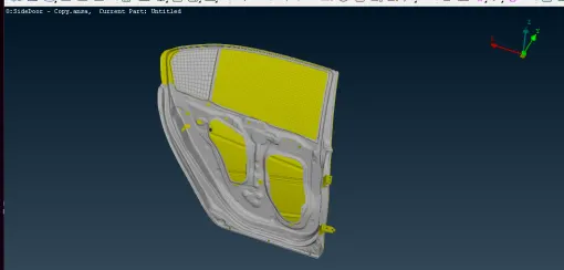
OBJECTIVE:
The objective of this challenge is to create and apply different PIDs for different components and perform suitable connections for the given Rear door FE model.
PROCEDURE:
Firstly import the model in ANSA software and open it following the given steps:
In toolbar, go to file > open > select the file >ok
1. Creating and applying different PIDs for different component:
- After opening the model, it is in the entity mode. So for better visualization, we shift to PID mode.
- Now it is observed that the whole model is in single PID, so we assign different PIDs for different components as below:
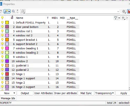
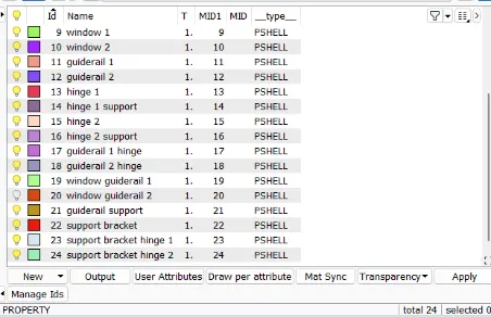
- After assigning the PIDs, the model will look like as follows:
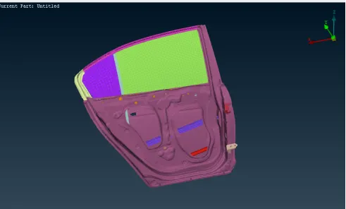 2. Deploying Various Connections:
There are different types of connections to deploy at various parts.
1. Rigid Body Element (RBE2) Connection:RBE2 connections are rigid connections which prevents movement along translational and rotational axes.
Here two types of RBE2 connections are used which are many nodes RBE2 and two node RBE2.
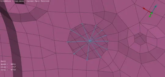
1.1 Many node RBE2: For that go to NASTRAN deck>Elements>RBE2>Many nodes. Then select all the nodes on the perimeter of the hole and after pressing middle mouse button, master node will get automatically selected. After confirmation the connection will form as follow:
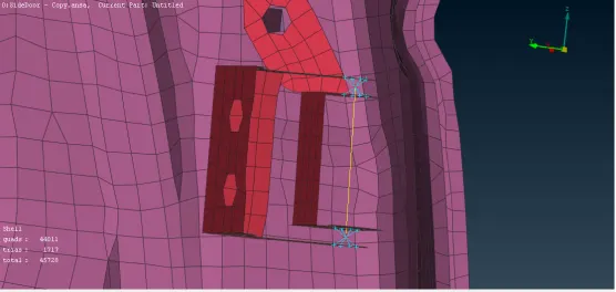
1.2 Two Node RBE2( Hinge): For that, first we have to create many nodes RBE2 connection on both sides of the hinge. Now go to NASTRAN deck>Elements>RBE2>Two nodes and select the nodes. After confirmation, hinge connection is formed. But in this case, rear door has to rotate about z-axis. This can be achieve by assigning 12345 as CM in connection manager tab. The connection will look like as below:
 2. Bolt Connection:
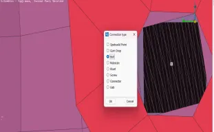
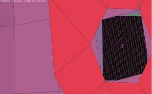
In this method, create COG point by going to TOPO>Points>On COG and select the edges of the hole and create a point. Then go to the convert option and select the point and covert it into Bolt. This is shown as below:
Now go to Connections option and select the bolt. After confirming, Connection manager window will open. Then select the parts on which connection has to deploy and select FE Rep Type as BOLT. Enter the search distance and other properties as per the requirement and click on apply and realize. The connection will look like as below:
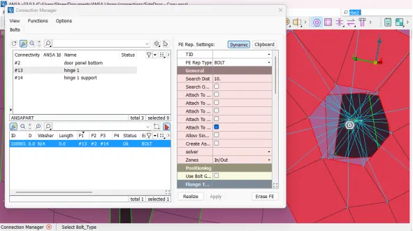
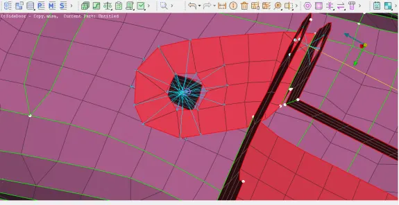
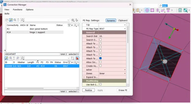
Here there are multiple slave nodes and a master node for each part and master nodes are connected to each other by RBE2 two node connection constraining all degrees of freedom.
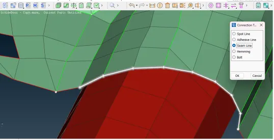
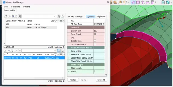
3. Seam Weld Connection:Seam weld connections are used to connect two mating parts.Generally we use two types of seam weld connection which are Overlap shell and Y-Joint shell. Here we use Overlap shell because the parts are parallel to each other. For that go to Topo>Perimeters>Feat2Curve option and create a curve. Then convert this curve into seam line.Then go to connection manager and select FE Rep Type as Overlap Shell. Enter the search distance and select the parts. After clicking on apply and realize option, Seam weld connection will formed as below:
 4. RBE3-HEXA-RBE3 Elements connection:
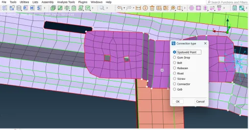
To deploy this type of connection, create COG point at the surface of the part. Then convert this part into spot weld point as below:
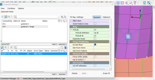
 Then go to connection manager, select the point and press middle mouse button. Then select the parts and select FE Rep Type as RBE3-HEXA-RBE3. Enter the search distance and click on apply and realize. The connection will look like as below:
 5. Concentrated Mass Element Connection:
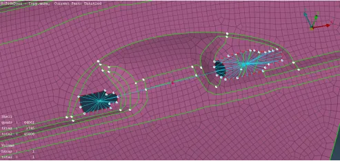
For mechanisms such as handle, motor etc. concentrated Mass Element type of connection is used. To establish this type of connection on door handle, create RBE2 many nodes connection on both slots of the handle, then create the master node in between the slots by using RBE2 two node connection. This will act as COG of both slots. Now assign the mass on COG by going to Nastran>Elements>CONMi>CONM2>Nodes and select the COG point and press middle mouse button. A CONM2 card will open. Then enter the mass in M column in tonnes and press OK.
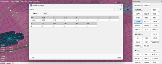 Concentrated Mass Element Connection is created as follows:
  6. RBE3-CBUSH-RBE3 Elements connection:
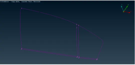
This is also called as weather strips connection because this type of connection is used to create connection between window glass and door panel. To deploy this type of connection, firstly crate a curve along the edges of window glass by using Feat2Curve option as below:
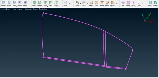
 Now convert these curves into Spotline.
 Now Open the connection manager and select the spotline and press middle mouse button. Then select the FE Rep Type as RBE3-CBUSH-RBE3 and select the parts and enter space distance to deploy the connection. Then enter the properties as shown below: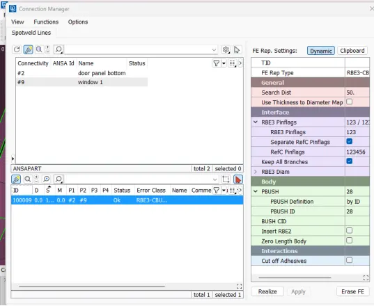
Create a new CBUSH property and assign it to the connection. Then click on Apply and Realize. The CBUSH connection will form as follow:
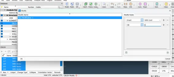
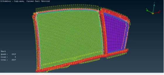 Now it is necessary to align local coordinates with global coordinates. For that open the CBUSH property card and select all the bush connections and press modify. The modifications are done as below:
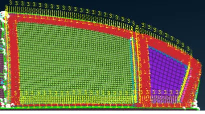
  Final connection will look like as follows:
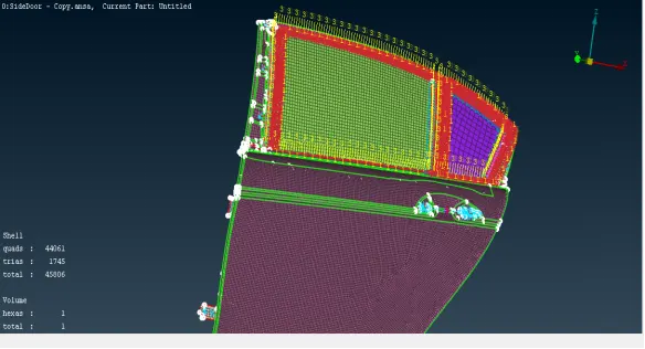
  Final model Image after deploying all the connections:
 LEARNING OUTCOMES:
1) Performing this challenge enables to create different types of connections.
2) Learn to assign mass to the parts.
3) Knowing about the uses and applications of deploying connections in modelling.
CONCLUSION:
After performing systematic approach, PIDs are created and connections are applied successfully to the given rear door model of a car.