Week 4 - 2D Meshing for Sheet Metal
AIM:
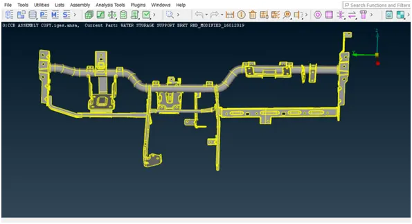
For the given CCB CAD model, Check for the Geometry cleanup, Take the mid surface, and Mesh it with the below 2D element Quality Criteria.
GIVEN:
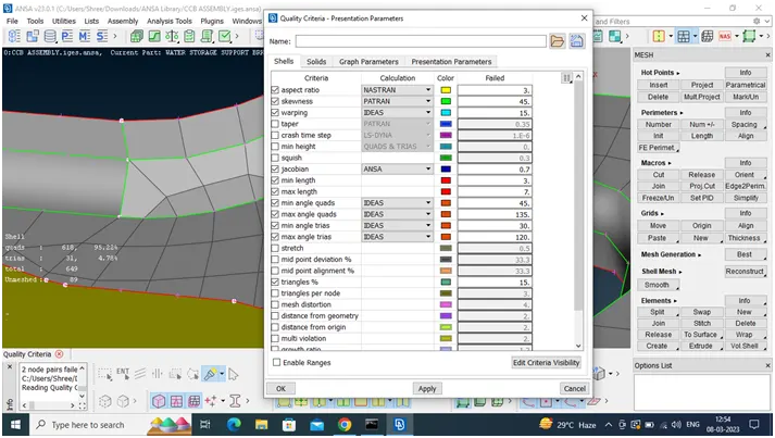
- No. Quality Criteria Value
1 Target/Average Length 5
2 Minimum Length 3
3 Maximum Length 7
4 Aspect 3
5 Warpage 15
6 Skewness 45
7 Jacobian 0.7
8 Minimum Quad Angle 45
9 Maximum Quad Angle 135
10 Minimum Tria Angle 30
11 Maximum Tria Angle 120
12 Tria Percentage 15
OBJECTIVE:
The objective of this challenge is to perform the geometric cleanup and extract the mid surface of the components of given CCB CAD model and then mesh this components following the given Quality Criteria.
PROCEDURE:
- Firstly import the CCB model in ANSA software and open it following the given steps:
In toolbar, go to file > open > select the file >ok
- After opening the model, one should perform topo cleanup to prevent geometrical errors. For that go to the topo option on right hand side of toolbar and go to faces> topo and select the whole model and hit the middle mouse button. This way topo cleanup is carried out.
3. After that geometry check is performed by going to the checks > Geometry and selecting all the parameters, geometry check is executed as shown in below image:
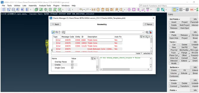
These errors were fixed by right click on them and choose fix option.
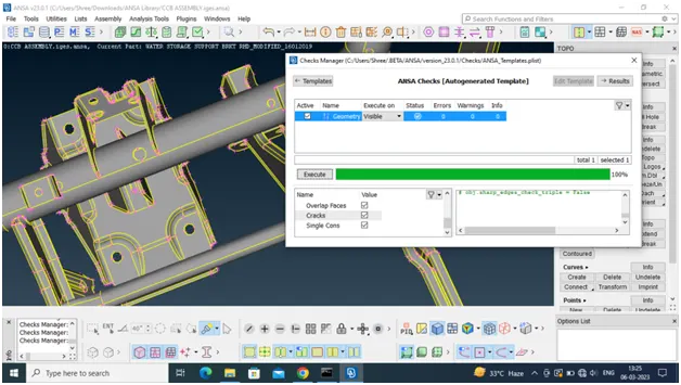
- Now select each part one by one for meshing and follow the steps given below:
1) Go to the model browser and select the parts one by one for meshing. The given CCB model contains 29 parts having different thicknesses as follows:
- LH RHD BIW end support with manipulator -1.60mm
- RH RHD BIW end support with manipulator -1.60mm
- Buzzer Support Bracket- 1.60mm
- RHD CCB Tube- 1.60mm
- RHD Cluster support bracket- 1.60mm
- RH RHD Floor bracket- 1.60mm
- RHD GSL attachment support bracket- 2.50mm
- GSL attachment- 2.50mm
- RHD GSL support bracket- 2.00mm
- GSL & IP support bracket- 1.60mm
- RH RHD Intermediate support- 1.60mm
- IP Lower Trim Panel support bracket- 1.60mm
- RHD CCB bracket locator- 1.60mm
- GSL RH RHD CCB bracket Center- 1.60mm
- LH RH CCB bracket end cap- 1.60mm
- RH RHD CCB bracket end cap- 1.60mm
- LH RHD CCB bracket pillar- 1.60mm
- RHD Knee Cover support- 1.60mm
- RHD LWR Glove box support bracket- 1.60mm
- LH RHD Lower Splitted support- 1.60mm
- RHD Steering attachment- 2.50mm
- Brake Pedal Area support bracket- 1.60mm
- RHD Telematic unit bracket- 1.60mm
- LH RHD Upper Tunnel bracket- 1.60mm
- RH RHD Upper Tunnel bracket- 1.60mm
- RHD Upper storage bracket 1- 1.60mm
- RHD Upper storage bracket 2- 1.60mm
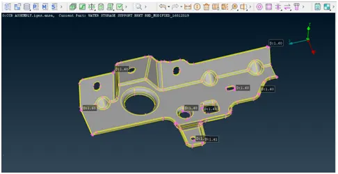
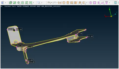
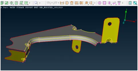
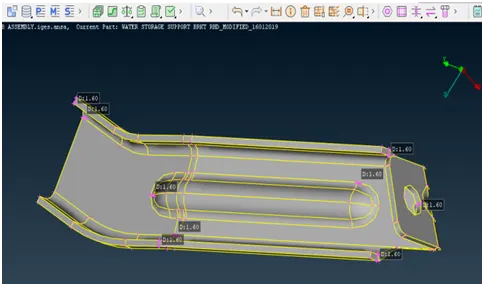
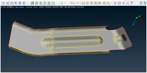
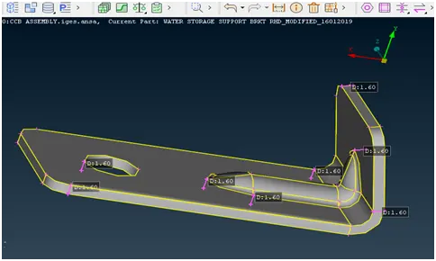
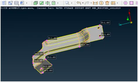
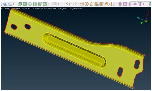
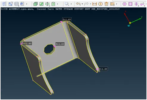
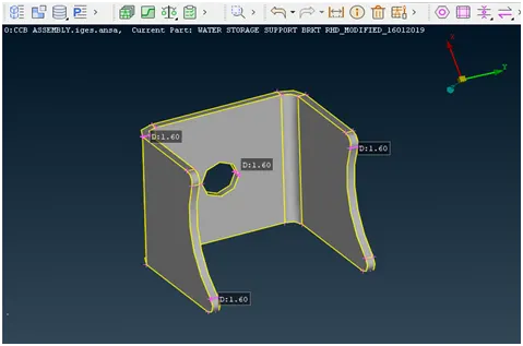
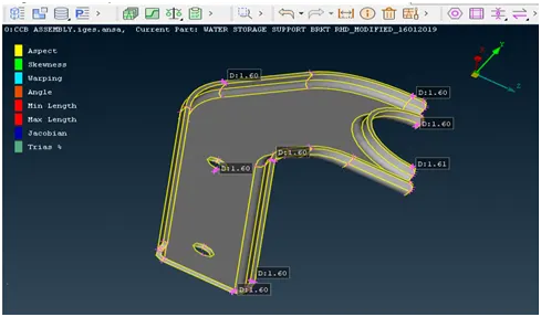
- RHD Water storage support bracket- 1.60mm
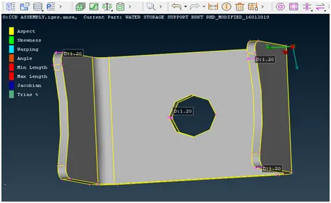
- Wiring Harness brackets- 1.20mm
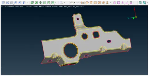
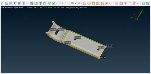
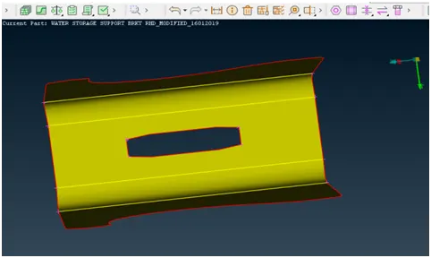
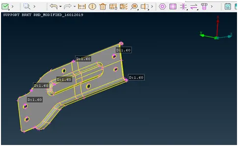
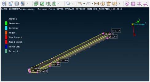
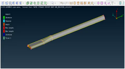
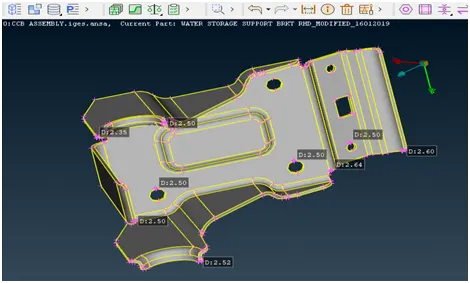
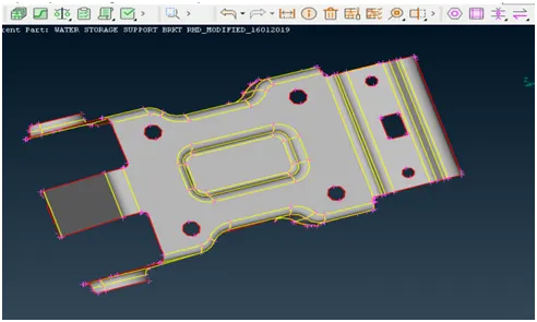
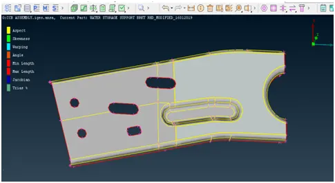
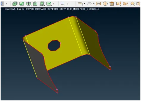
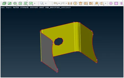
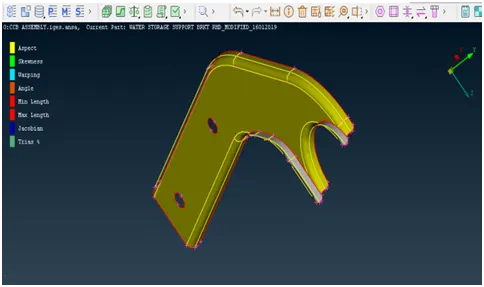
2) Extract the mid surface of the part using mid surface option. Choose the mid surface option in faces and select whole part. Then press middle mouse button twice and confirm the offset value.After confirmation, mid surface is generated. Then assign separate PIDs for midsurfaces of all the components. The thickness is assign by going to the List > Properties > New
3) After midsurface is generated for each of the component , assign the mesh parameters by going to the Utilities>Quality Criteria- Presentation Parameters and enter the given quality criteria and apply. (this quality criteria can be saved for future reference).
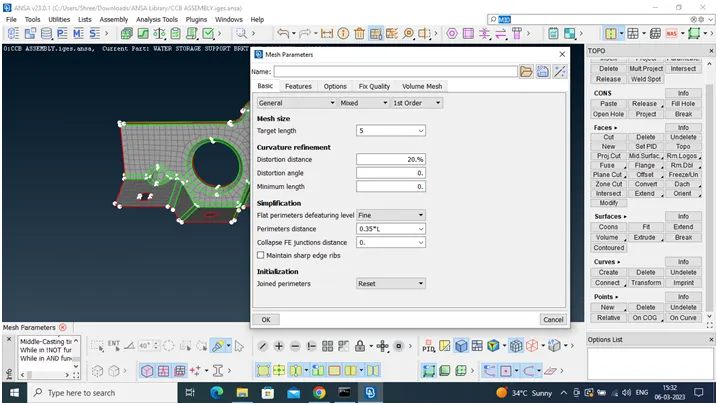
4) Now go to the mesh module and assign element length by going to the Perimeters > Length >target element size. Enter the target length for all the components as 5.
5) Then divide the surface into small sections using Macros> Cut so that better mesh flow is generated.
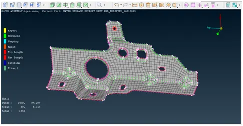
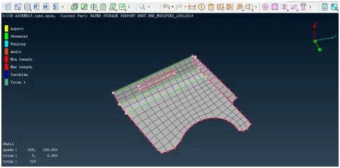
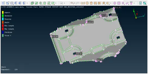
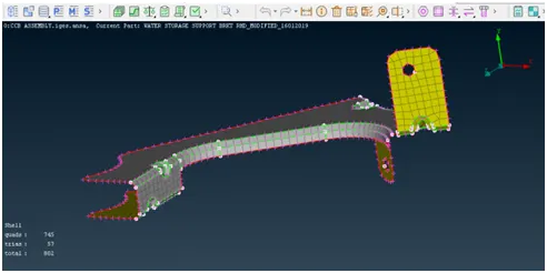
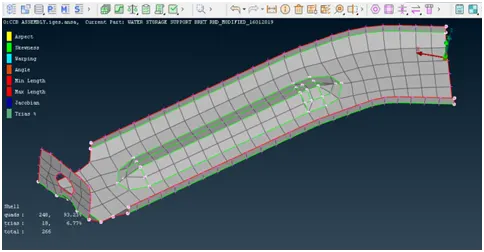
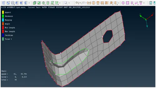
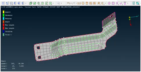
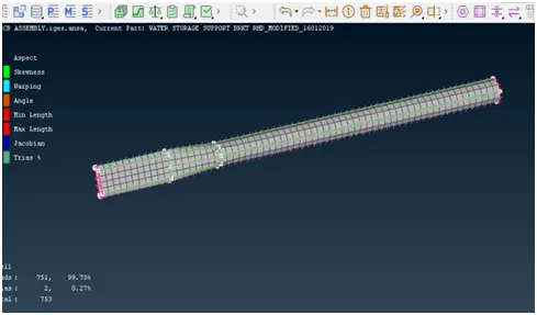
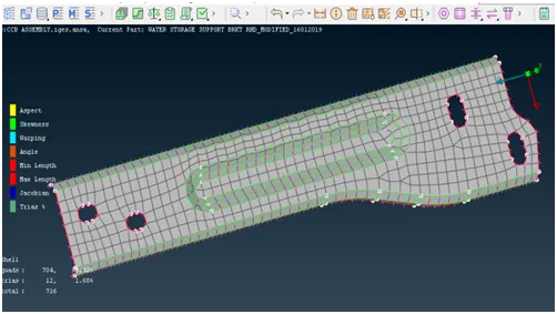
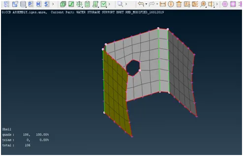
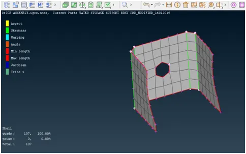
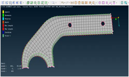
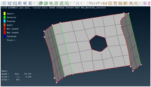
6) Now meshing is done using Mesh Generation> Best. This tool generates best possible mesh flow for the surface.
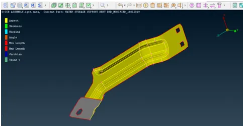
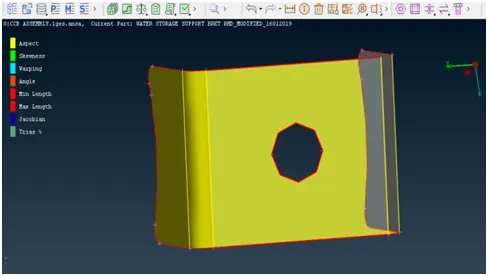
7) Then refined the mesh by using Shell Mesh> Reconstruct. Make sure that there are no rotating quads and opposite trias present in the model. Reduce trias near to free edge or holes or on the fillets. OFF elements must be zero after giving quality criteria.
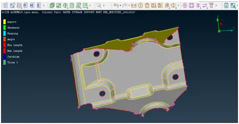
8) After meshing, smooth option is used to get good quality mesh flow.
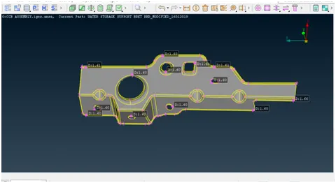
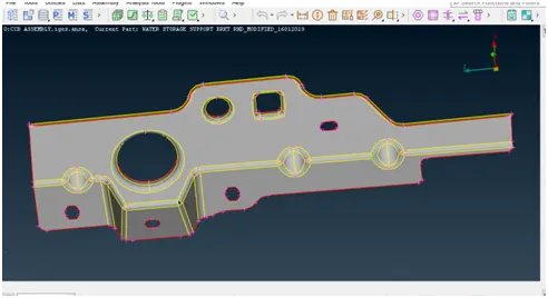
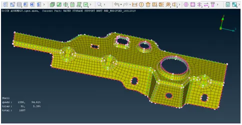
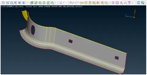
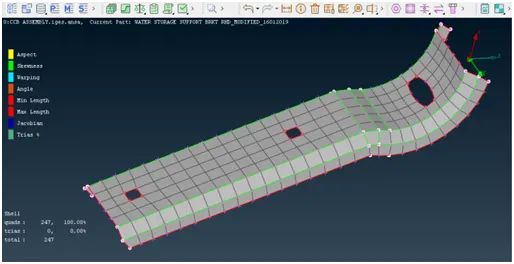
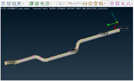
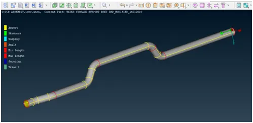
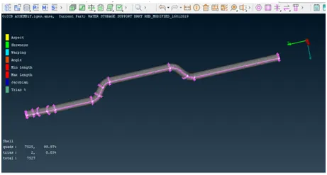
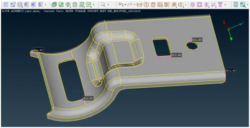
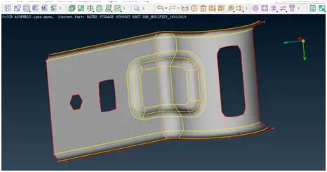
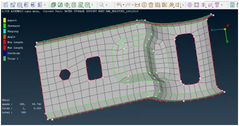
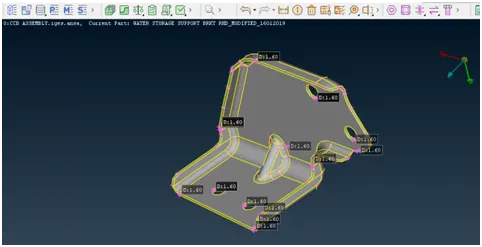
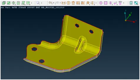
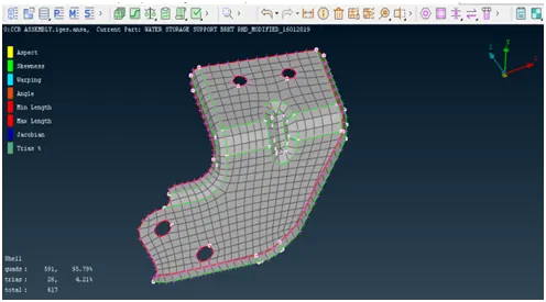
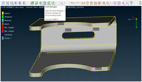
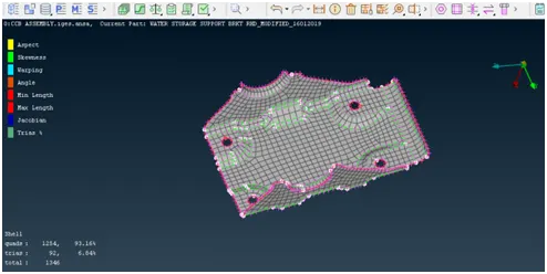
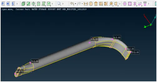
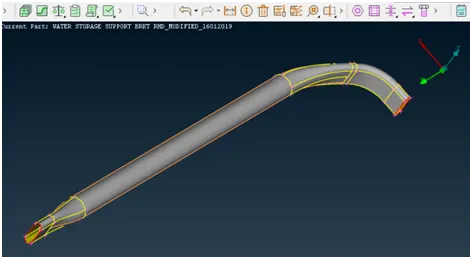
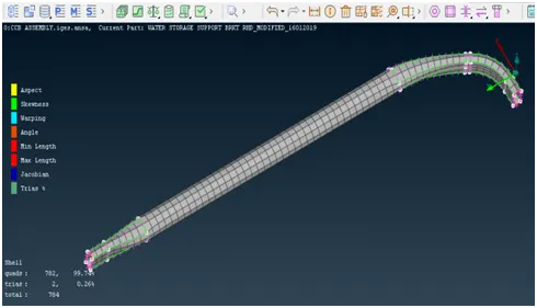
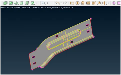
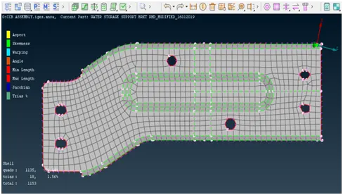
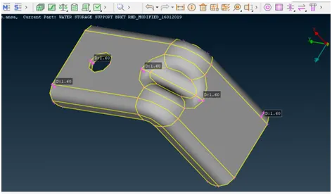
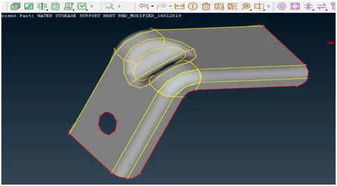
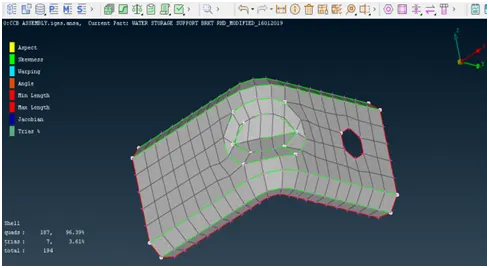
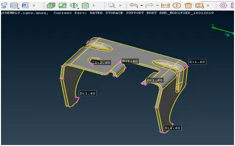
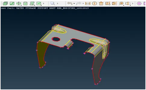
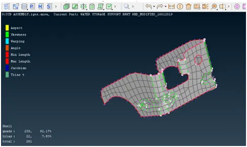
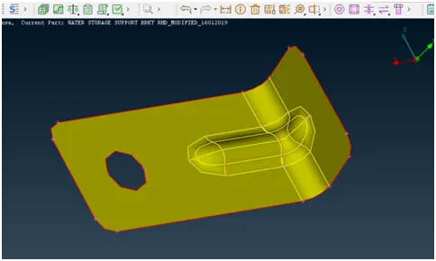
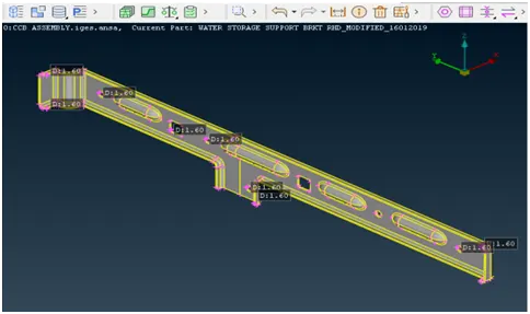
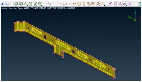
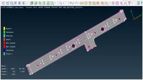
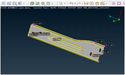
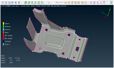
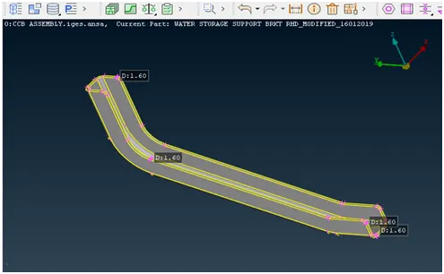
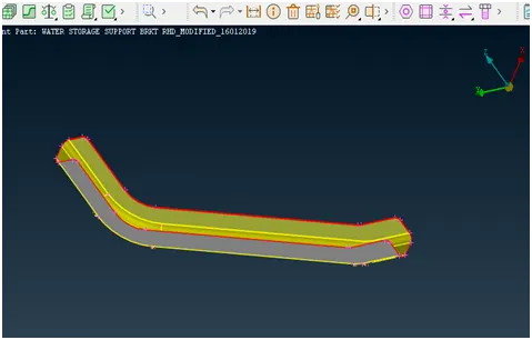
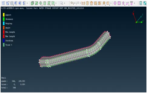
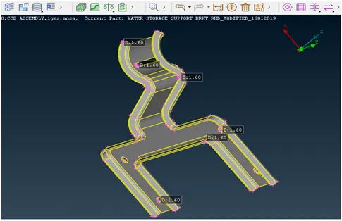
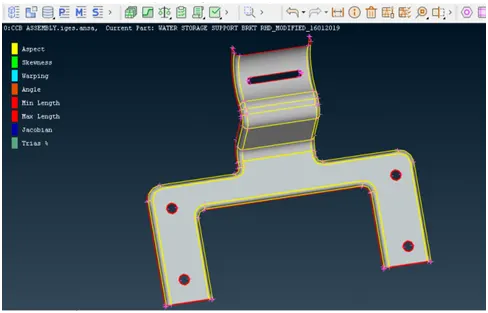
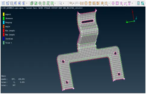
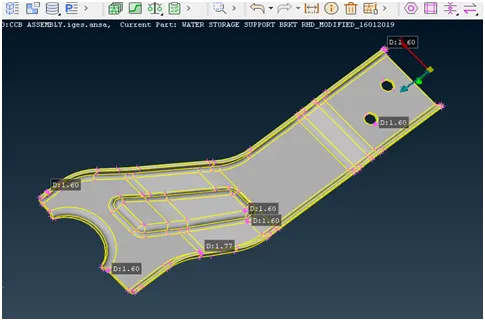
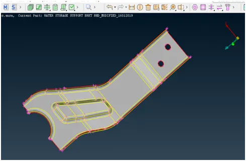
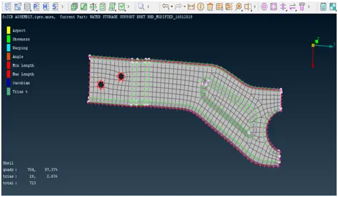
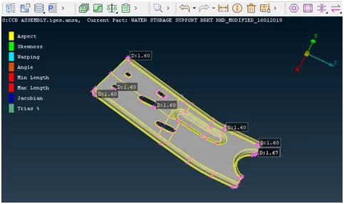
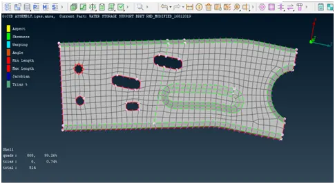
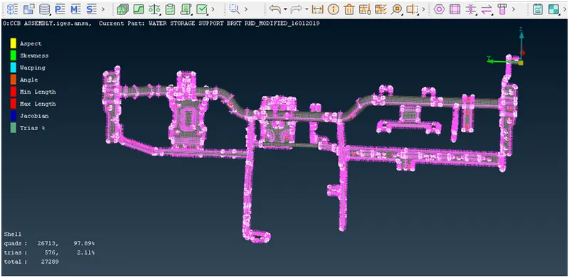
Final Model Image:
LEARNING OUTCOMES:
1) Performing this challenge enables to use different tools in the software.
2) Learning of both the options for extracting midsurface.
3) Knowing how to use different tools to get good quality mesh.
CONCLUSION:
After performing proper geometrical cleanup, extraction of midsurfaces for each component and assign thickness to each of them, the given CCB CAD model is meshed according to the given quality criteria.