Week 9 - Creating connection for Rear door
Creating Connection for Rear Door- ANSA Week 9 Challenge
1. Aim
- For the given Rear door FE model, Create and Apply different PIDs for different components.
- Perform suitable connections for the FE model.
2. Objective
- Import and assign different PIDs concerning the PID region
- Perform suitable connections on the model.
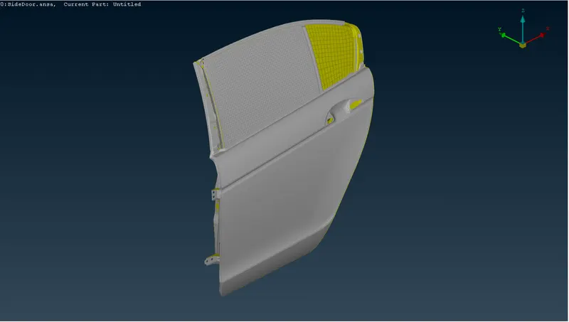
Fig 1: Isometric View of Model
3. Procedure
Step 1: Import the Model and PID Assigning
First, the model is imported and loaded on ANSA v22.1.0. The model contains only one PID. We must create and assign each PID region to different PIDs for the proper connections.
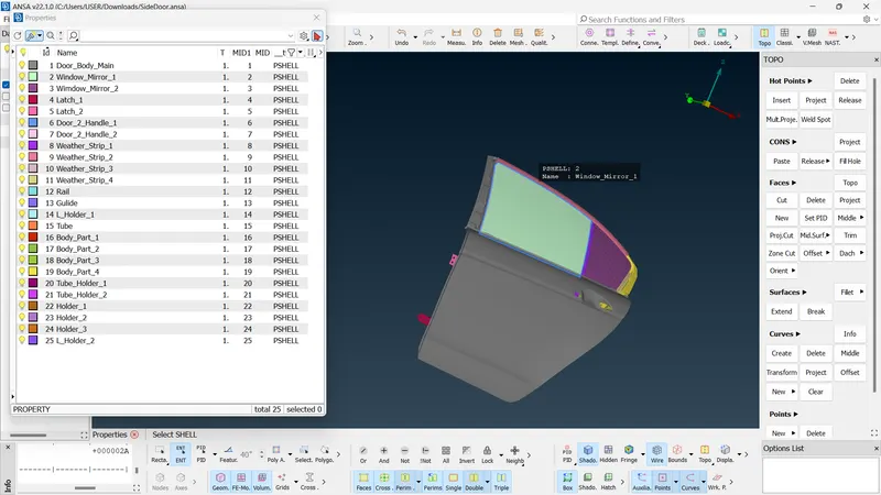
Fig 2: PID Assigning
Step 2: Connections
The following process is connecting the suitable parts on the door panel for stimulation. Inspect the given model and perform convenient connections using RBE2. RBE2 (Rigid Body Element Type 2) is used to connect bodies rigidly and restricts the motion x,y and z-axis.
Cluster Method
- Decks Module >> Nastran >> Elements >> RBE2 >> Many Node
Select nodes (Slave Nodes) for which the connection is to be made. After the confirmation, those slave nodes are connected to a single node called as Master node.
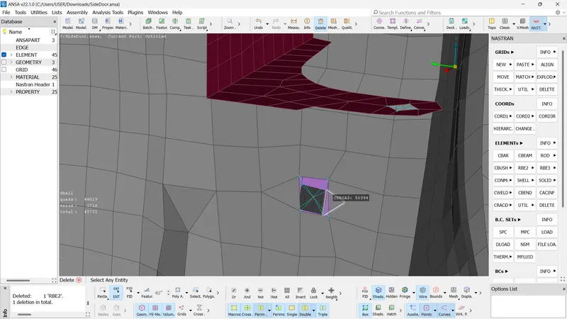
Fig 3: Cluster Method
3D Point Method
It is an automated method. Here we make a COG on the bolt hole and convert it to bolt representation and realise the connection using the connection manager. Make a 3D point of any hole and covert it into a Bolt
- Convert >> 3D Points >>Select The 3D Pont >> Bolts.
Using the connection manager we can realise the connection to this bolt.
- Connection Manager >> Select The Bolt >> FE Rep Type=bolts
Specify all parts (P1, P2, P3, P4)
- Double Click P1 >> F1 >> Deselect ANSAPart >> Select one of the PIDs where the connection is needed. >> Ok
Also, change the Zones to In/OutX and give the search distance to 30. After giving Apply and Realise we can see that the connection is made between the selected PIDs.
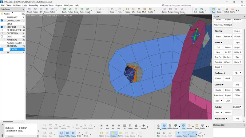
Fig 4: Bolt Representation Using 3D Points
Latch Representation
The latch mechanism can be a different representation. Here the bolt holes are connected using RBE2 Many Nodes and the master nodes of these are connected using RBE2 Two Nodes. The latch connection should be restricted in one direction. While connecting the Two Nodes, the DOF should be restricted in one direction. (CM=123456 >> CM=12345).
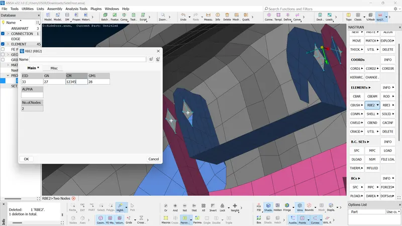
Fig 5: DOF Assigning Of Latch Connection.
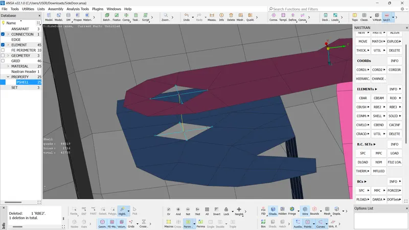
Fig 6: Latch Connection
Door Handle Representation
The door handle is connected and we have to assign the mass of that handle (In tons) to the master node. The mass of the handle is 100g (0.0001 tons)(As per the Video). The handle is connected in two respective holes. Firstly the connections of those holes are done individually using RBE2 Many Nodes and the master nodes of those two connections are connected using RBE2 Many Node and give a Main Master Node. Assign the mass of the handle to the main master node using
- Elements >> CONMi >> CONM2 >> Nodes >> Select The Main Master Node >> Give M=0.0001 tons >> Apply
Here the main master node has a mass is equal to 0.0001 tons (100g).
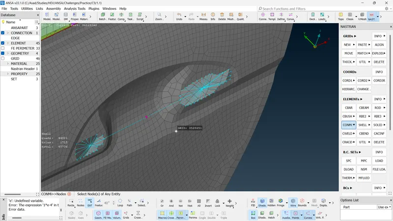
Fig 7: Door Handle Representation
Spot Weld
In the rear door model, some components are connected using spot welds. So we have to provide the connection as a spot weld. Make a 3D point where the spot weld is required and convert it into a spot weld point.
- Convert >> 3D Points >>Select The 3D Pont >> Spot Weld Point
Using connection manager we have to assign P1 and P2, also the give search distance =30. Select FE Rep Type as 'RBE3-HEXA-RBE3'. Change the DOF of RBE3Pinflags (123 to 123456). Create (Shift + /) and give PSOLID ID. Then apply the settings and realise the connection.
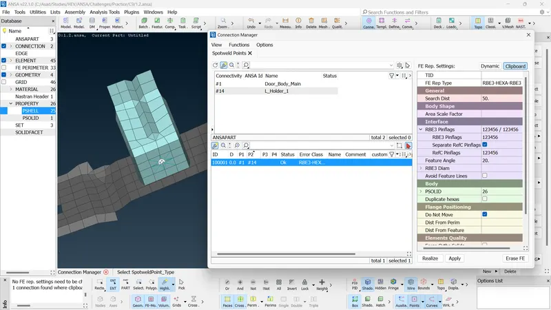
Fig 8: Connection Manager For Spotweld
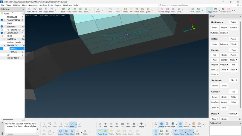
Fig 9: Realised Connection
Window Glass Connection (Weather Strip-Glass)
The Window Glass is should be connected using CBUSH elements to the weather strip or door body. The window glass should be modelled as in a closed position.
For creating the connection, we have to create curves using Feat2Cur. around the window glass. Also, the bottom curve should be copied to the 1 unit dY axis. Then these curves should be converted to spot lines by
- Convert >> Curves >> Select Curve at a Time >> Spotlines >> Ok
Then using the connection manager we have to create CBUSH elements.
- Connection Manager >> Select The Spotline >> FE Rep Type = RB3 CBUSH RBE3 >> Assign P1 and P2 (Using F1) >> Search Distance = 50 >> Create and Give PBUSH ID (Give the values of stiffness K1, K2, K3, K4, K5, K6) >> Turn ON Keep All Branches >> Apply >> Realise.
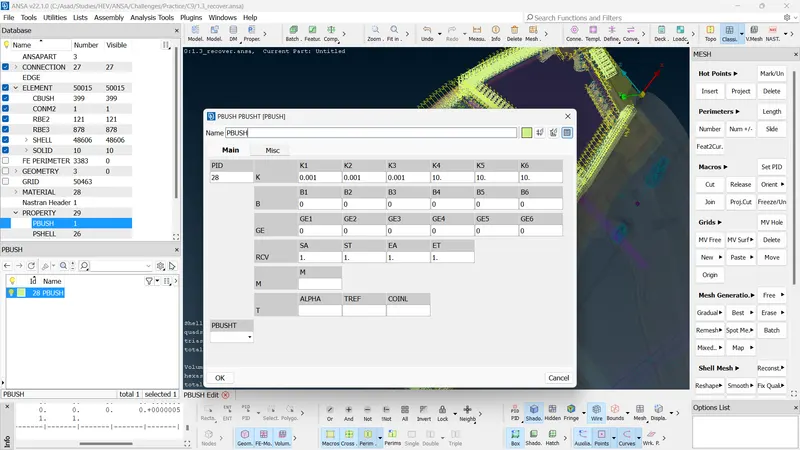
Fig 10: Stiffness Values of PBUSH ID
The process is repeated in all spot lines one by one
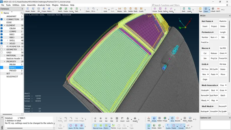
Fig 11: Realised Connection of CBUSH Elements
The process is repeated in all spot lines one by one. After that, the CBUSH elements should be oriented on the basis of global Coordinates.
- Database (F12) >> Elements >> Select CBUSH and Select All CBUSH elements >> Right Click >> Modify >> New Modification >> Set Modify Rules (Orient = With Cords, CID = 0) >> Ok
Seamline Connection
Some parts should be connected using seamlines. For that, we have to create a curve where using Feat2Cur and convert it into a seamline and deploy the connection. Set the P1 and P2. Also, select the FE Rep type = Overlap Shell. Assign base plate (P1/P2), Steplength, Width, Weld PID (Create and Select), and Search Distance. Select Root Shells = Double row. Apply and realise the connection.
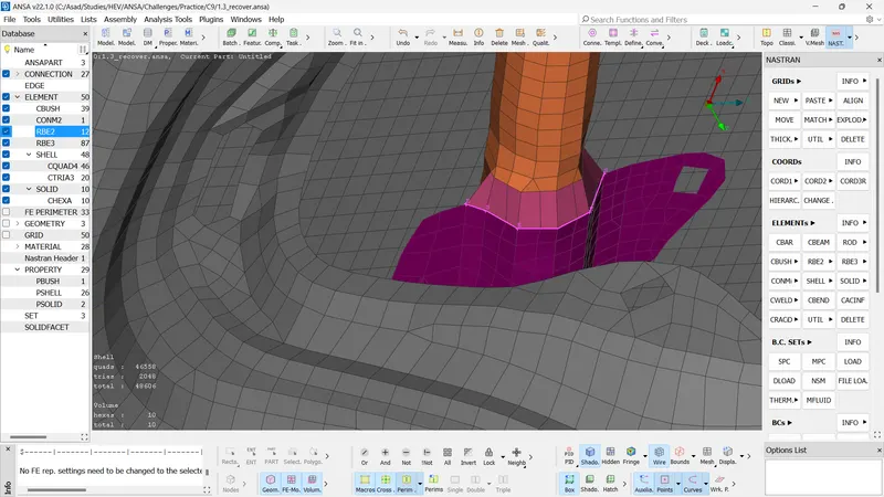
Fig 12: Seamline Connection
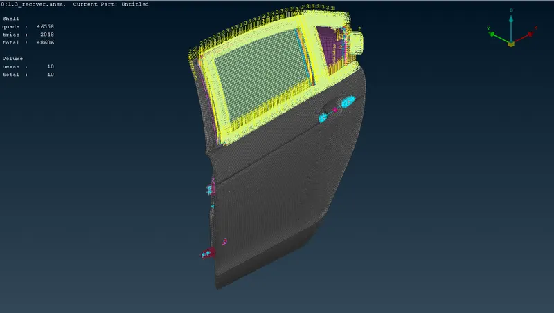
Fig 13: Final Result
4. Result
- All connections are made and all parts are connected to the assembly.
- The connections are made by Seamline, Spotline, Bolts, and Spotweld.
5. Conclusion
- All parts in the rear door assembly are connected using suitable connection methods and the model is ready for the stimulation.