Week 3 - 2D meshing for Sheet metal
Meshing Of A Hood Component - ANSA Week 3 Challenge
1. Aim
- To Generate a mesh on a given Hood component model after a proper geometry cleanup and mid-surface generation using 'ANSA' Preprocessing Software.
- Ensure the generated mesh obeys the mentioned quality criteria and the corresponding thickness of each surface assigned to the mesh.
2. Objective
- Import and perform a geometry cleanup on the given hood model using ANSA GUI
- Fix errors shown during the geometry check-ups.
- Identify the model by measuring the thickness, whether the model is plastic or sheet metal.
- Generate a mid-surface from the cleaned model.
- Mesh the generated mid-surface and reconstruct the mesh to satisfy the following quality criteria.
Quality Criteria
| Sl No. | Quality Criteria | Value |
| 1 | Target/Average length | 5 |
| 2 | Minimum Length | 2 |
| 3 | Maximum Length | 7 |
| 4 | Aspect | 3 |
| 5 | Warpage | 15 |
| 6 | Skewness | 45 |
| 7 | Jacobian | 0.7 |
| 8 | Minimum Quad Angle | 45 |
| 9 | Maximum Quad Angle | 135 |
| 10 | Minimum Tria Angle | 30 |
| 11 | Maximum Tria Angle | 120 |
| 12 | Tria Percentage | 15 |
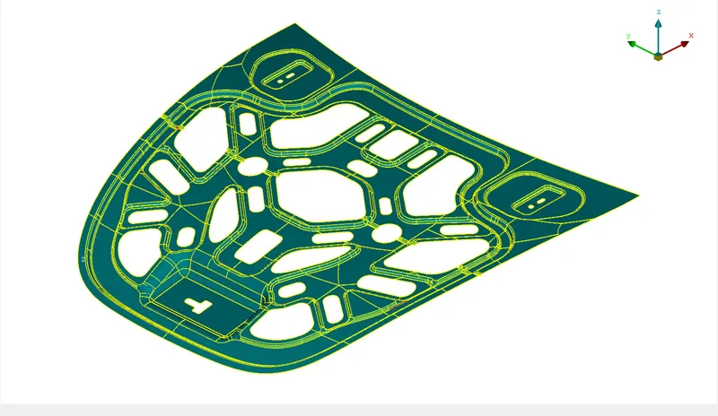
Fig 1: Isometric View Of Hood Model
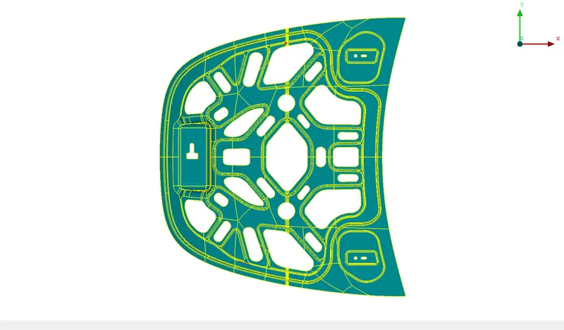
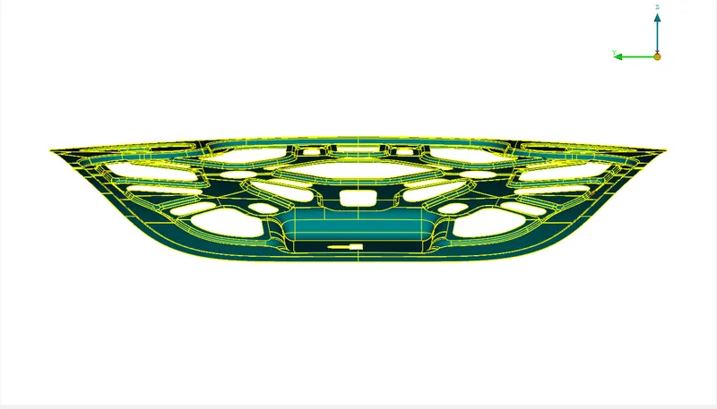
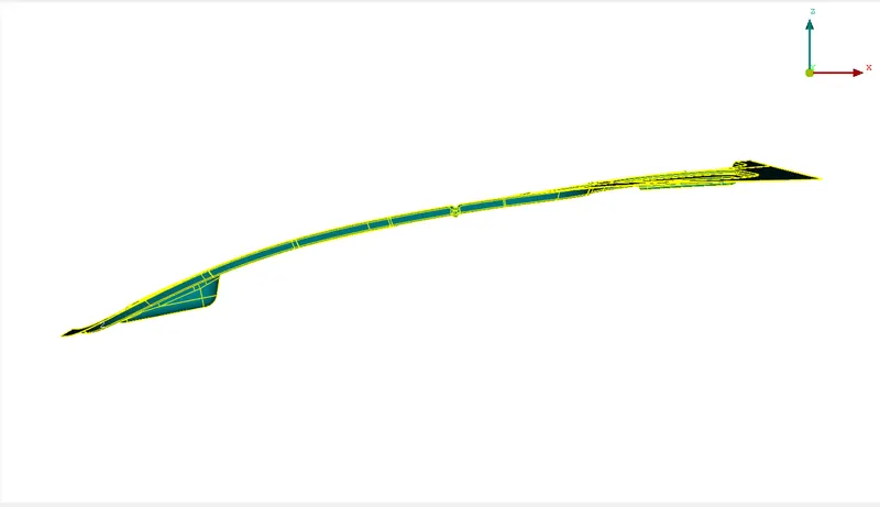
Fig 2: Top View Of Hood Model Fig 3: Front View Of Hood Model Fig 4: Side View Of Hood Model
3. Procedure
Step 1: Import the model to ANSA GUI
For preprocessing the given 'Hood Model', the CAD model should be open and loaded in ANSA v22.1.0.
- Open ANSA v22.1.0 >> New >> Open >> Open and load the CAD model of the hood.
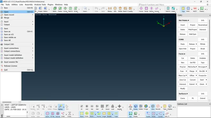
Fig 5: Import file to ANSA GUI
Step 2: Perform geometry cleanup
Initially, We need to check for the single CONS. Any single CONS (Red) present in the geometry needs to be converted into double CONS (Yellow) using the Topo operation.
- Drawing Styles bar >> Draw mode >> Entity (ENT).
- Faces >> Topo >> Right Click and drag to select the whole model (Selected cone shown in white color) >> Enter.
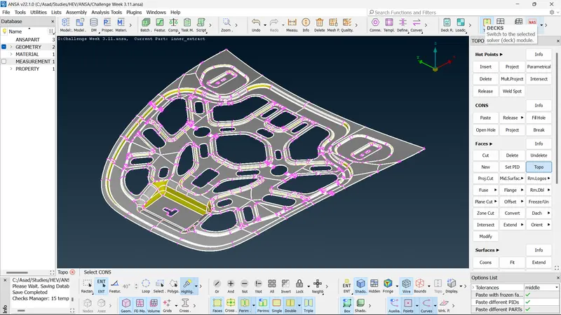
Fig 6: Topo Operation
Increase the resolution of CONS by changing the distance between the nodes (=1). It helps to understand the actual geometry of the CAD model. Before the meshing, the length should be changed to the target length as quality criteria prefer.
- Switch to mesh mode >> Perimeters >> Length >> Perimeter >> Right Click and drag to select the whole model >> Length (1-20) = 1 >> Ok.
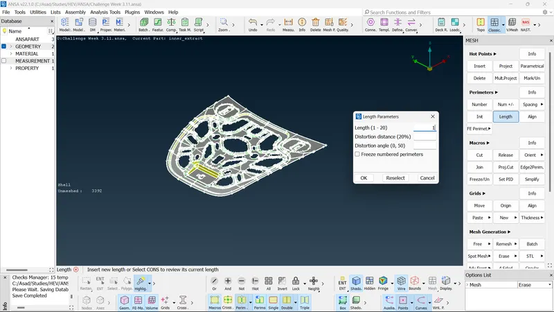
Fig 7: CONE resolution by Perimeter
- Switch to mesh mode >> Perimeters >> Length >> Macros >> Right Click and drag to select the whole model >> Length (1) = 1 >> Ok.
Fig 8: CONE resolution by Macros
For Geometry Checkups,
- Tools bar >> Checks >> Geometry >> Execute on 'All entities' >>Execute.
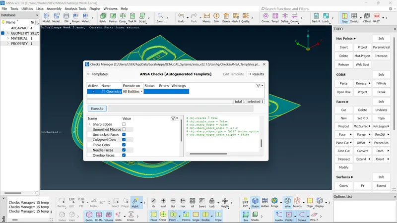
Fig 9: Geometry Check
After the geometry check, we can see the list of all errors in the geometry. The errors include Unchecked faces, Needle faces, Triple CONE, Cracks, etc. ANSA can automatically fix the majority of these errors by,
- Select all errors >> Mouse Right Click >> Fix.
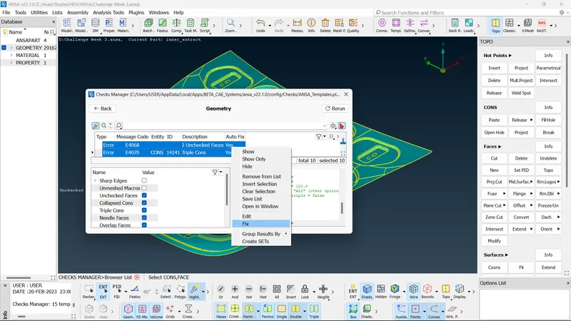
Fig 10: Auto Fixing of errors
As we can see, the majority of errors are corrected by ANSA itself. The remaining errors are cleared manually by using tools and carrying out specific operations. The operations used for the fixing of errors include,
- Focus bar >> Neighb >> Select CONS to show the neighboring faces.
- CONS >> Release >> Select CONS to release.
- Faces >> Topo >> Select faces to perform topology.
- Faces >> Delete >> Select and delete unwanted faces.
- Faces >> New >> Select and Create new faces.
- CONS >> Fill Hole >> Select and fill holes
After the necessary action, the errors are fixed and perform a geometry checkup once again to ensure every error is fixed. If everything is clear, the geometry check is completed and ready for mid-surface generation.
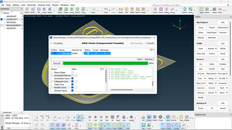
Fig 11. Sucessful geometry checkup.
Step 3: Thickness Measurement and Mid-Surface Generation
After the successful geometry check, the thickness of the model should be checked across the model. If the thickness is uniform throughout the model, we can conclude that the model is a sheet metal model. If the thickness is varying across the model, the model is plastic. For the thickness measurement,
- Utilities >> Measure >> Select hot points between 2 faces where thickness is needed >> Mouse middle click >> Repeat the same procedure randomly in the entire model >> 'Store' to store measurement.
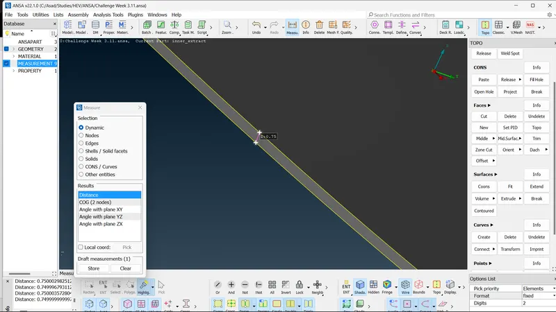
Fig 12: Measuring the thickness
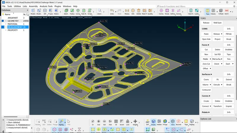
Fig 13: Check Thickness in the entire model randomly
As a result of taking 20 measurements randomly, it has been seen that the thickness of the model = 0.75mm, and it is uniform throughout the entire model. So the given CAD model is a sheet metal model. After that, we go for the mid-surface generation which can be done both automatically or manually. In this case, we use manual mid-surface generation, and it is done by using Offset operation.
- Faces >> Offset >> Featue Area Selection Tool >> Feature Angle Value : 40 >> Click the Upper face >> Option List >> Property >> Auto Create >> Offset Value : (+/-) 0.75/2 >> Ok .
Here we use the feature area selection tool and which is used for ignoring the neighbor surfaces that are taking a deviation of more than mentioned angle value=40. Also, the offset value polarity (+ or -) indicates the direction in which the mid-surface should be generated.
Also, we can perform a geometry check on the mid-surface and nullify the errors if necessary.
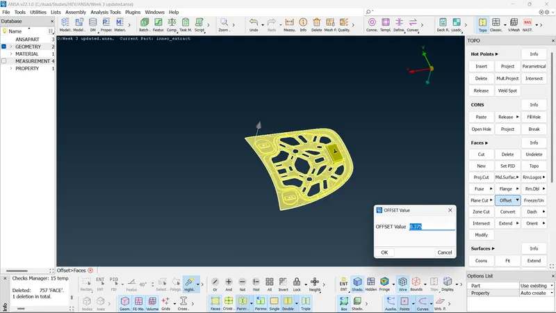
Fig 14: Mid-Surface Generation
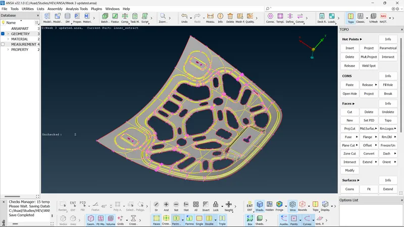
Fig 15: Generated Mid-Surface
Step 4: Adding Quality Criteria and Meshing
After the mid-surface generation, we have to add target/average length and other quality parameters. First of all, the model should be switched to mesh mode. For adding target/average length=5,
- Perimeters >> Length >> Perimeter >> Right Click and drag to select the whole model >> Length (1-20) : 5 >> Ok.
- Perimeters >> Length >> Macros >> Right Click and drag to select the whole model >> Length (5) : 5 >> Ok.
For the other quality parameters,
- Utilities >> Quality criteria >> Shells >> Mark Qualities >> Add Quality Criteria Values >> Presenation Parameter >> 'Turn On Element %' >> Detail On Demand Effect >> Drag to 'More Detail'. >> Apply >> Ok.
- Utilities >> Mesh Parameter >> Target Length : 5 >> Ok.
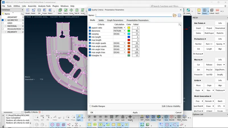
Fig 16: Quality Criteria Edit
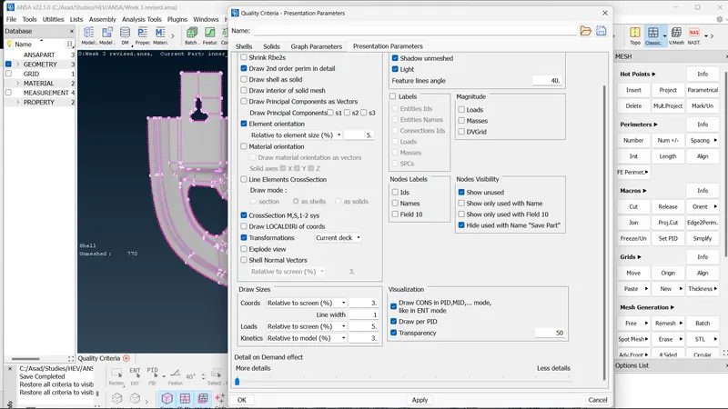
Fig 17: Quality Criteria-Presentation Parameters
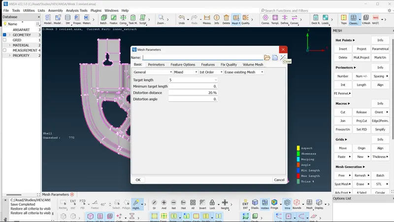
Fig 18: Mesh Parameters
By analyzing the mid-surface we can see that the model is asymmetric (Neglecting The Front Part) and then we make a cut through the middle of the model and delete another half. After cutting one-half of the model deleted and mesh the remaining part and mirror to construct the whole model. For cutting and deleting
- Switch to Topo Mode >> Faces >> Cut/Project Cut.
- Faces >> Delete >> Delete the other half of the model.
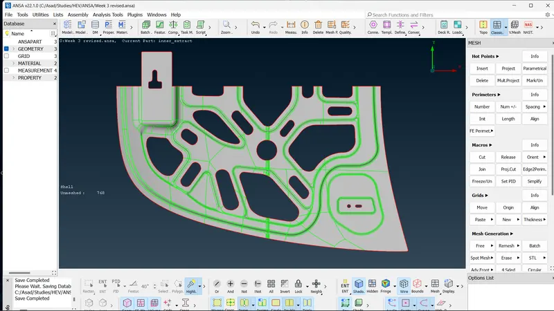
Fig 19: Cutting and Deleting of One Half
After the symmetric cutting, the meshing can be started on the mid-surface. Various methods for meshing can be used. In this case, we used meshing tools like Best Mesh, Spot Mesh, etc.
- Mesh Generation >> Best/ Spot Mesh
The following generated mesh has some quality criteria issues that should be addressed. For this, we have to reconstruct or reshape the existing mesh and create new elements where it should satisfy the quality criteria. For reconstructing and improving mesh quality
- Mesh Generation >> Erase
- Shell Mesh >> Reconstruct/ Improve/ Zone Cut/ Smooth/ Collapse
- Elements >> Split/ Swap/ Join
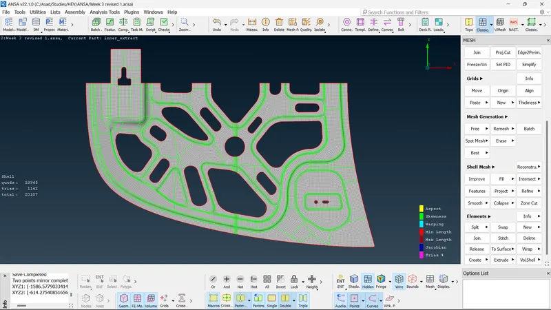
Fig 20: Reconstructed Mesh
Now, a high-quality mesh is produced on half of the model. Because of its symmetry, the transform tool can be used for creating another half.
- Utilities >> Transform >> Copy >> Entities >> Select Area Excluding The Front Part >> Symmetry >> Use: Default Symmetry Plane >> Apply >> Part: Same Part >> PID: No Offset >> Ok >> Finish.
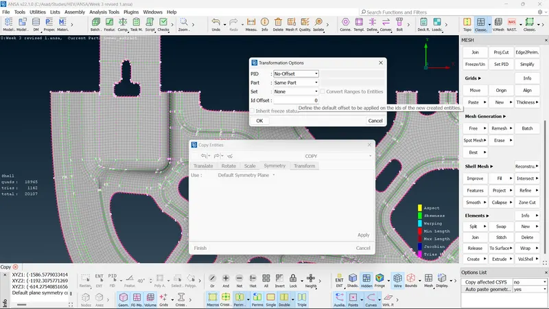
Fig 21: Tranform Operation
After the full model generation, perform topo for joints between the 2 halves to join them. The meshing of the hood component is now completed.
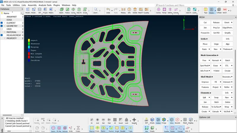
Fig 22: Final Result
4. Result
- The meshing of the hood component is completed and every element/shell in the mesh satisfies the quality criteria.
- The mesh consists of a total of 39334 no. of shells and it includes 37402 quads and 1852 trias.
5. Conclusion
- The given hood component meshing is completed as per the quality criteria mentioned. The meshing is done after the successful geometric clean-up and proper mid-surface generation for the hood component.