Week 9 - Creating connection for Rear door
Creating connection for Rear door
Objective:
For the given Rear door FE model, Create and Apply different PIDs for different components.Appropriate connections should be given whenever required.
Following the below steps :
- Taking the geometry for portal.
Download the geometry from the portal and open it in the ANSA software . It looks like ,
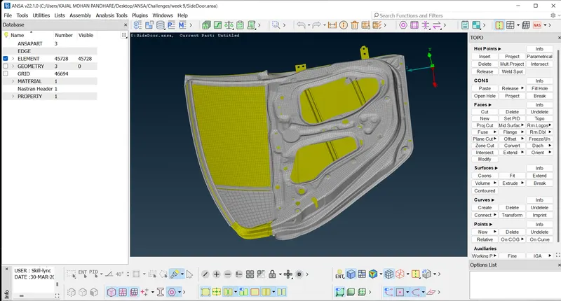
The model is already meshed.
So, for making the connections we will go in NASTRAN tab
In the Elements we get the RBE2 option.
RBE2 is use for the connection of Rigid elements (where stiffness is max and No deformation).
for ex. for Nut n bolt connection where DOF is ristricted completly.
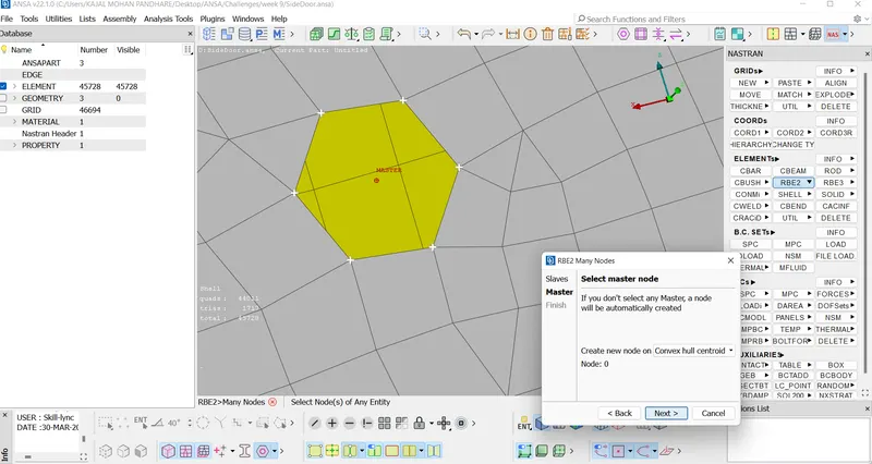
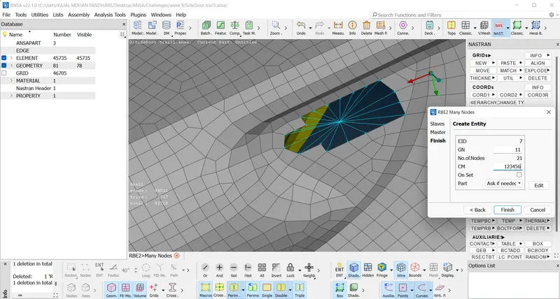
In RBE2 select the nodes as shown below img,on middle click we get next option, now we get the Master node. and get the connection.
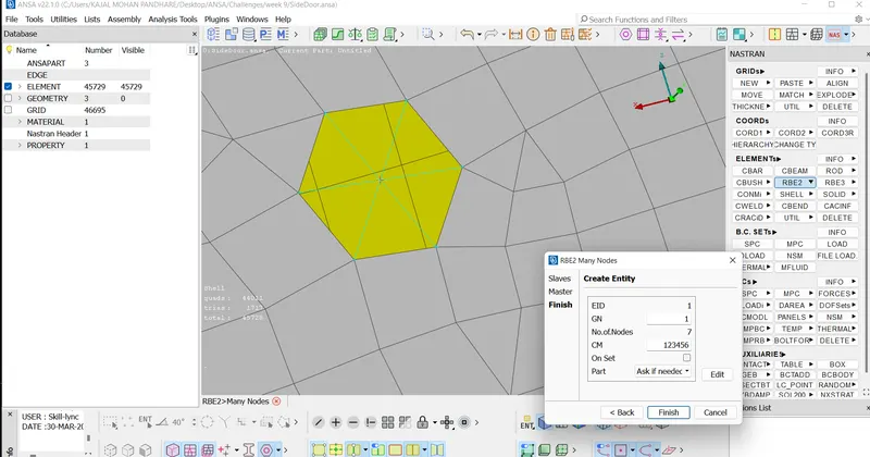
Here we get the CM option which has value 123456.(1,2,3-translational DOF in X,Y,Z direction resp and 4,5,6-rotational DOF in X,Y,Z direction resp) as shown below img.
Now we will do the connection of door opening and closing,
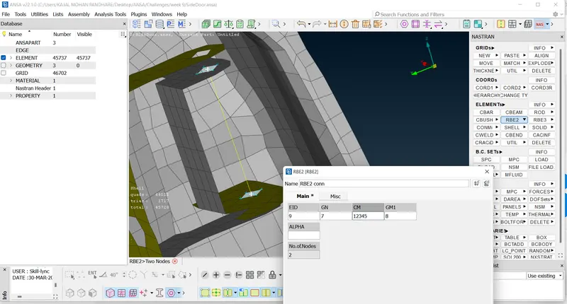
here also create the connection using RBE2 ,then we will connect the two mater nodes as shown in fig .
But here as door open and close so it rotate around the z axis ,so we don't restrict the rotational moment around the z axis (6).so in CM we select only 12345 not 6.
Shell Weld -To coonect two components which are parallel to each other.
we will connect the one part to other by using the same RBE2 . First select some entity of above c clamp and the select the some elements of the rod . we will get the connection as shown below.
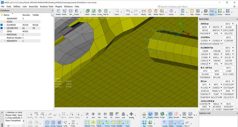
Handle connection
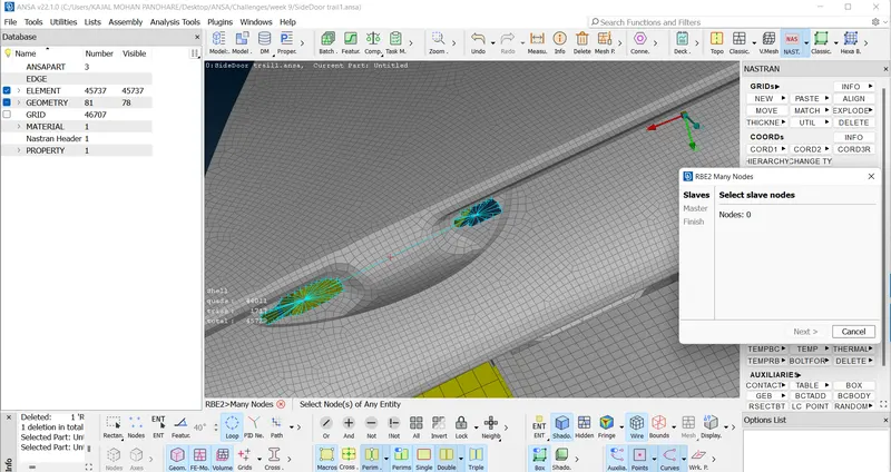
As similar way connect through the RBE2 ,selecting the node using loop option after that we get the master node .
Connect the both master nodes .
Door handle has some mass so we add mass to handle connection.
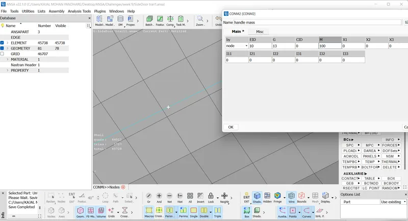
After applying the mass we get the master node more dark in red color. As shown in below img.
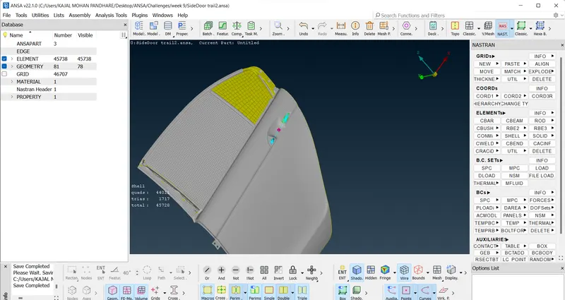
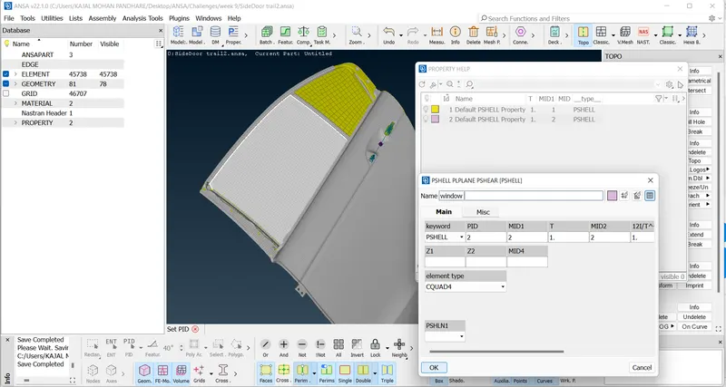
Now connecting the Window to the Rail through the C bush connection.
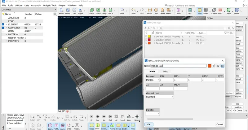
Create the curve using the Cons2curve option in Curves as shown ,
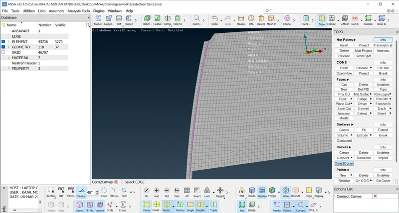
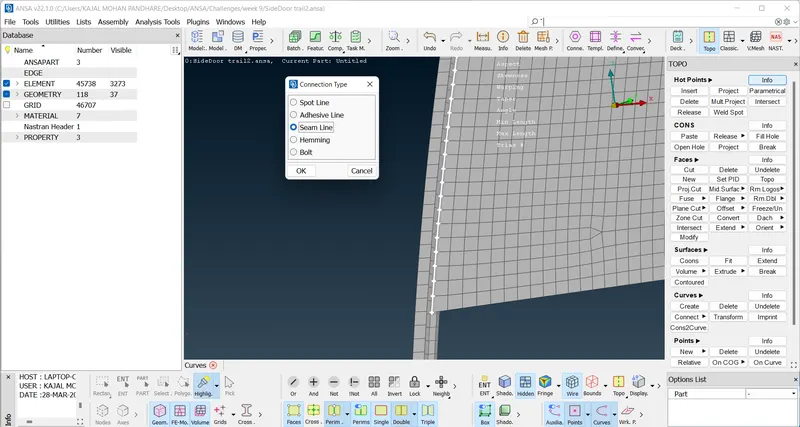
Select the curve and provide a connection type as a Seam Line.
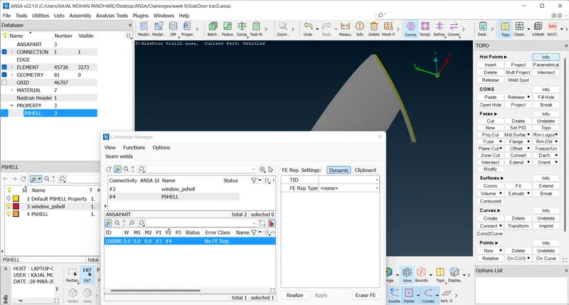
Use the Connection Manager option select the line middle click it , we get the window below , so we have to add the parts in P1 and P2 .
So right click on P1 then press F1, select the PID of Window , double click and press Enter.
#3 will reflected under P1 because PID of window is 3.
Similarly we do for the Rail , we get #4 in P2 because PID of Rail is 4.
Then select the FE Rep Type as a RBE3-CBUSH-RBE3
add steps 50
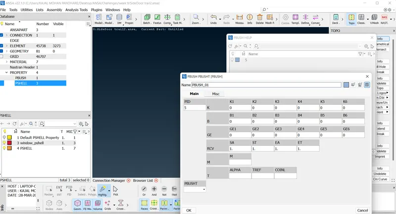
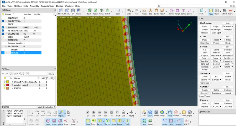
Create the PID of the bush, so we will press '? ' we get the window for slecting PID so we create new PID for bush as BUSH 01 press OK. Select that newly created PID option by double clicking it .it will reflect as PBUSH 5 .shown below,
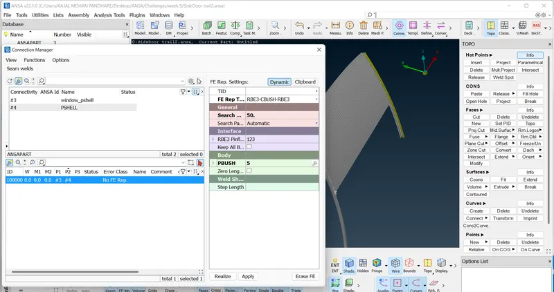
Press Apply and Realize . We get the C bush connection shown below . Follow the same procedure for other side of window.
Conclusion :
We connected the
1.Bolt holes using RBE2 connectors.
2.Clamps for Door opening and closing using RBE2 connectors, also connect two master nodes for rotation along z axis.
3.Weld join between C clamp and Rod using RBE2 connectors.
4.Handle connection by providing mass .
5. C Bush connectors between Window and Rail.