Week - 5 - 2D meshing for Plastic components
Objective:
For the given Plastic Bottle Cap model, check for the geometrical errors and take the mid surface by suitable mid surfacing techniques. PID and Thickness assignment has to be done for all the mid surfaces. Mesh the same with the given element Quality criteria.
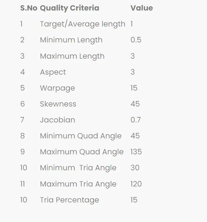
Quality criteria:
Following the below steps :
- Taking the geometry for portal.
Download the geometry from the portal and open it in the ANSA software .
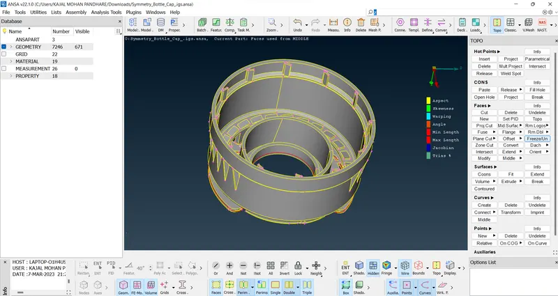
2.Do Topo on the following model :
To connect the geometry together do Topo.
3.Geometry cleanup:
Do Geometry check to see any errors are present in geometry or not .If errors are there Fix the errors .
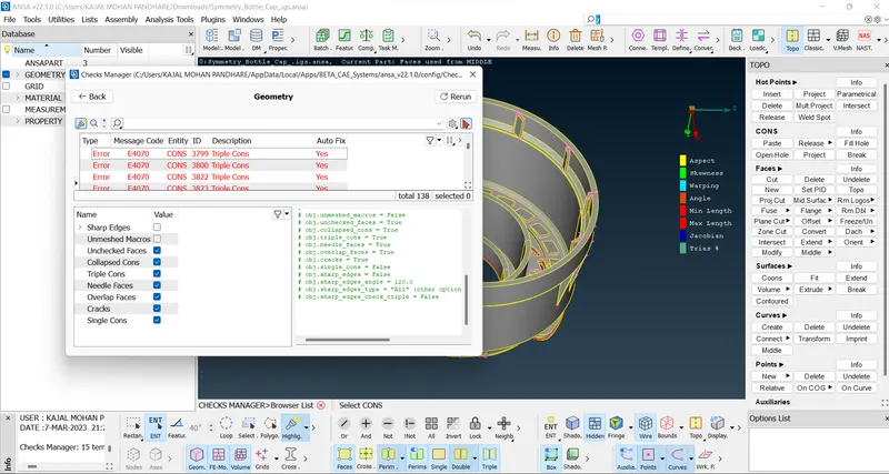
Here we got the errors after Executing ,
We fixed the errors and got the clean geaometry.
4.Midsurfacing :
Take one by one part from parent geometry & do midsurfacing of each part seperately.
First measure the Thickness of parent geometry. Here we got the different thickness as shown ,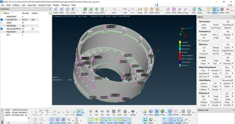
So, we take midsurface of each part sperately using different options,
for outer cylinders we selected Offset from Faces option,used Feature angle and selected the upperface of geometry .Then after clicking middle mouse button we get the arrow and pop up to give the offset distance .If direction of arrow is away from the geometry use -sign to offset.
After clicking middle click we get the option to delet the original faces or not,so click on 'No'.
Also use Middle from Faces option to create midsurfcae for the face having different thickness.
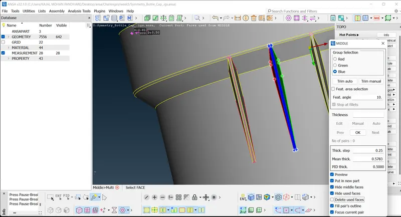
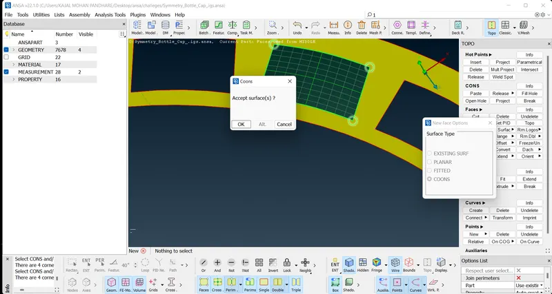
Use New faces option to fill the gap of midsurface,
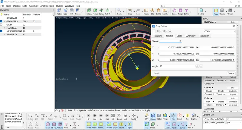
As the fins are around cylinders, we can use Rotate option in Transform to copy the same.
If the surface is not connected properly, we can use Extend in Faces option to join it.
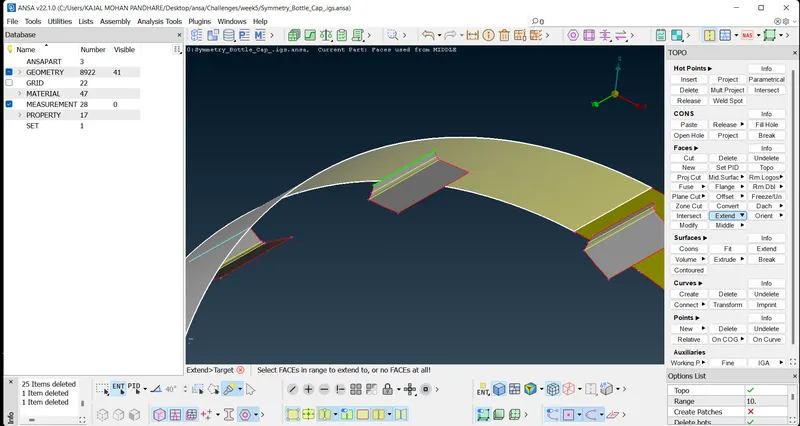
Like this using different option for different component according to the geometry of component,we get midsurface of all components.
Create seperate property card for midsurface.
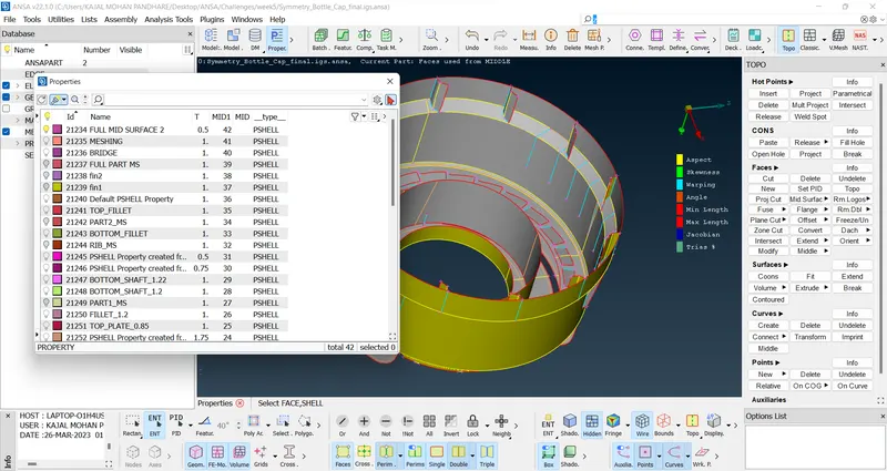
Follow the same procedure for all the parts ,we get the Midsurfaced geometry .
- Meshing
Take one by one part from midsurface geometry & do meshing of each part seperately.
Switch to Mesh Module ,choose Classic Mesh option .
Use length option from Perimeter ,on middle click pop up box opens put 1 there.
Set Mesh Parameters as per given requriments.
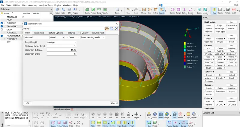
Se Quality Criteria as per given requriments.
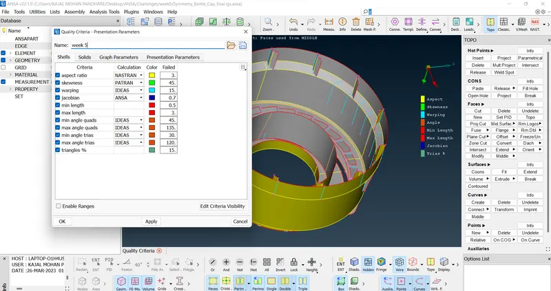
Select only given parameters & put the values as per requirement. Select the part & use Best option from Mesh Generation to generate mesh ,
After meshing we don't get the proper mesh as per quality criteria, so use Reconstruct option from shell mesh .
Try to reduce trias using Reconstruct,Split, Smooth,Collpase options from Shell Mesh .
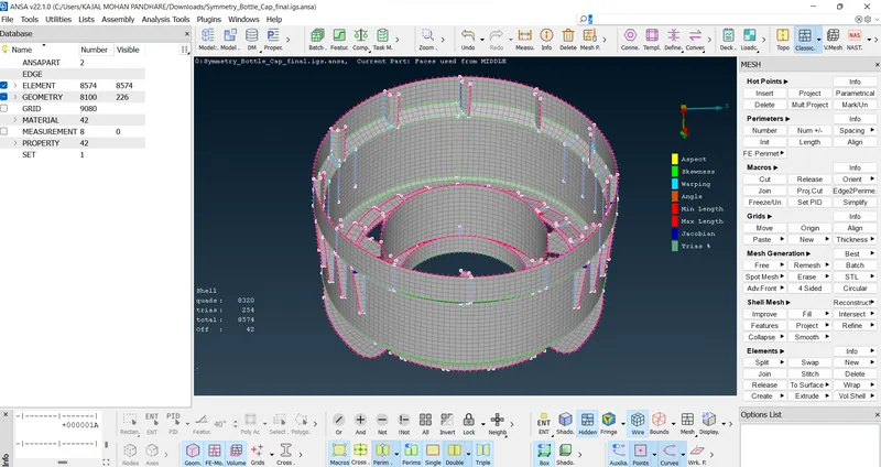
We reduce Trias and the final mesh we got,
Smillarly we do meshing for all the components .
Assign proper thickness to the mid surface and compare the same with the Parent geometry by performing “Draw shell as solid” in Quality criteria > Presentation parameters.
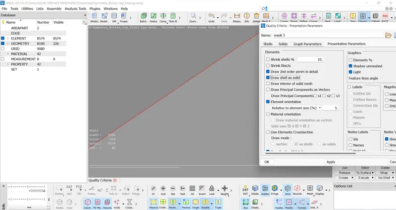
It looks like,
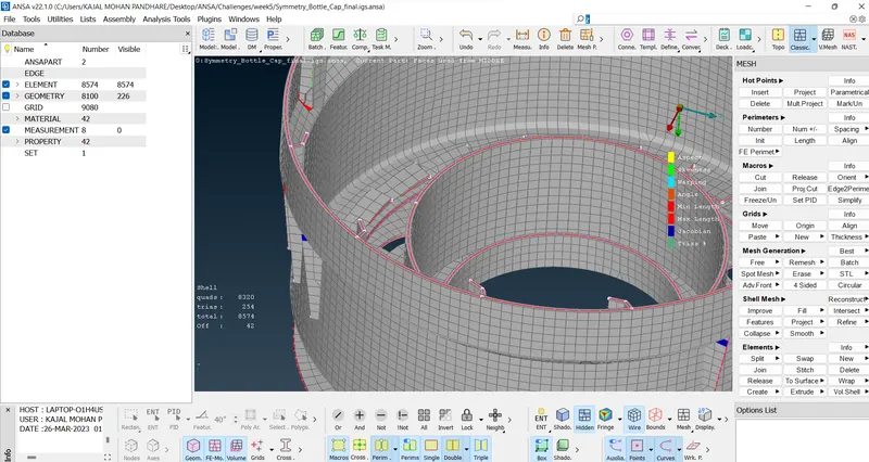
Final Mesh model: