Week 9 - Creating connection for Rear door
Aim - To Deploy appropriate connections for a Rear Door of a Car.
Objective - To Deploy connections using various connection techniques for a rear door FE model using ANSA.
Different types of connections we will be deploying are as follows
1.Creating Different PID’S for different parts of a door component
2.reating RBE2 1D Elements for bolt joints.
3.Creating RBE3-CBUSH-RBE3 element for window’s connection with door
4.Creating RBE3-HEXA-RBE3 element for the spot weld joint.
5.Creating RBE2 Element and Applying mass for a door handle.
Connectors:
A connector is a geometric constraint that defines how a part is connected to another part in an assembly model.
Connectors are used in FE modelling to represent the kinematic conditions of a system that are physically present. Connectors in FE modelling include welds, bolts, adhesives, rigids, etc.
The advantage of connectors is the ability to create multiple connections at a single time. Hundreds or even thousands of connections that would normally have to be created manually one at a time can be mass created, even before the part is meshed.
Procedure: -
- First the Model is Imported into the ANSA
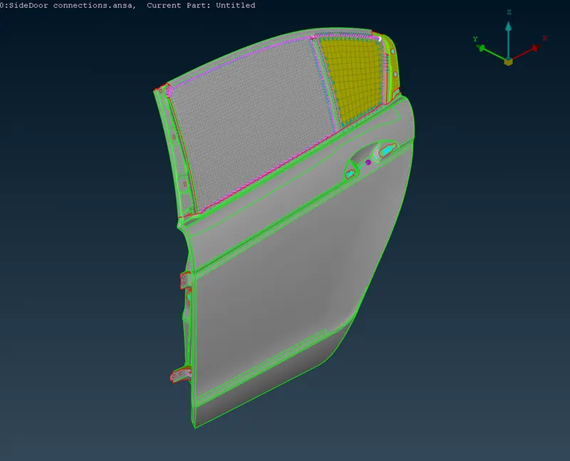
- There are several parts in the geometry we have to provide different PID’S to different parts. This is done in order to properly distinguish them and to prevent any confusion while deploying connections in between them
- Parts with different PID’S & PID’S provided to them are shown below.
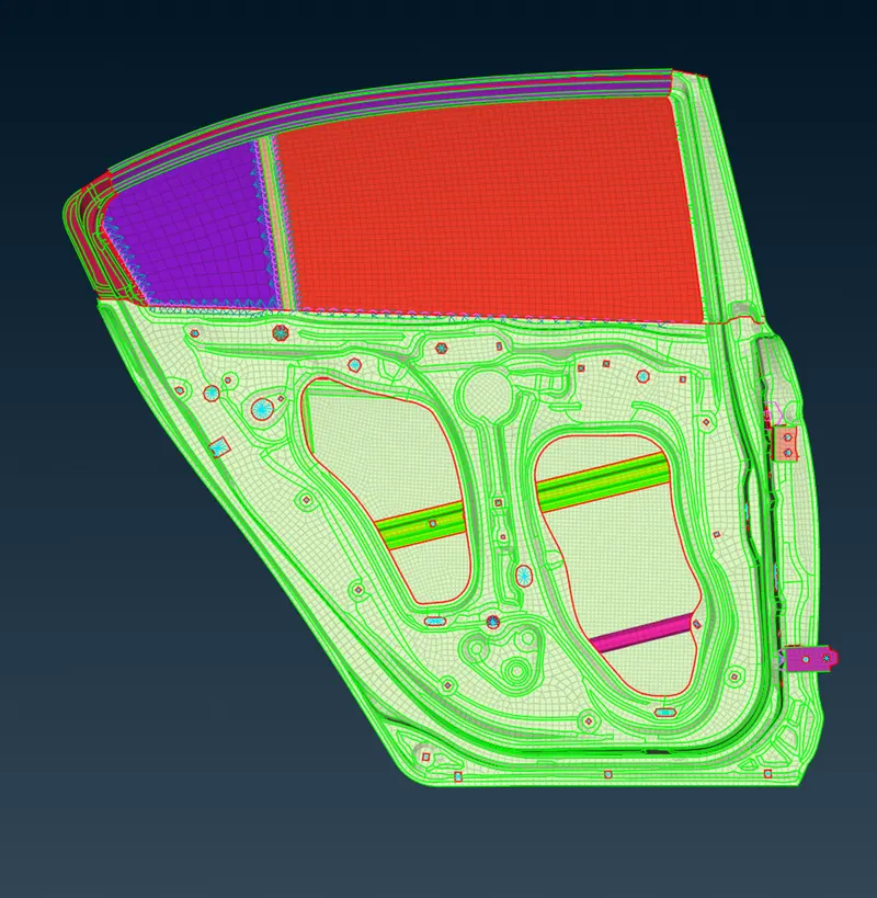
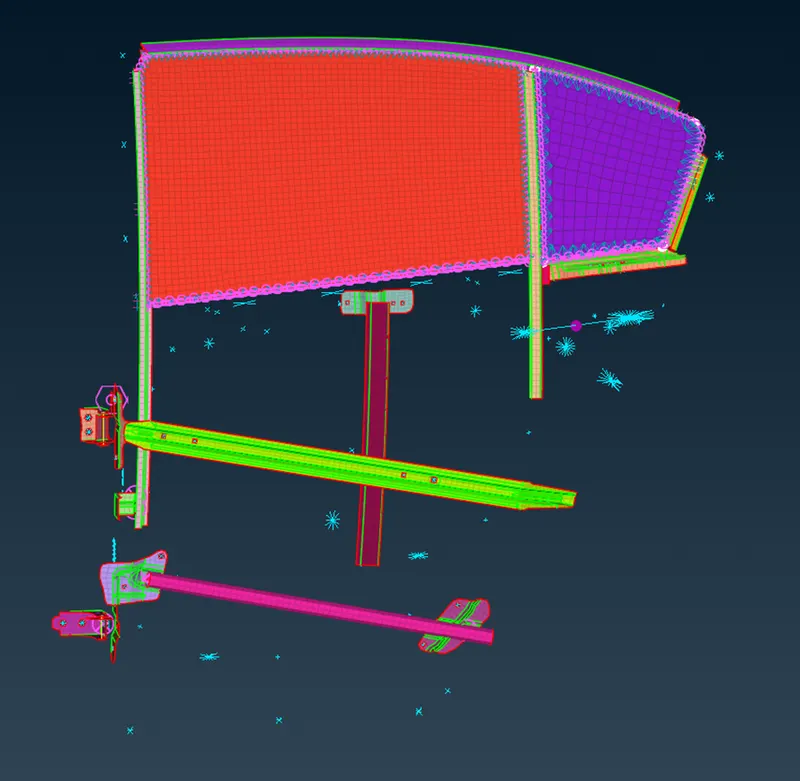
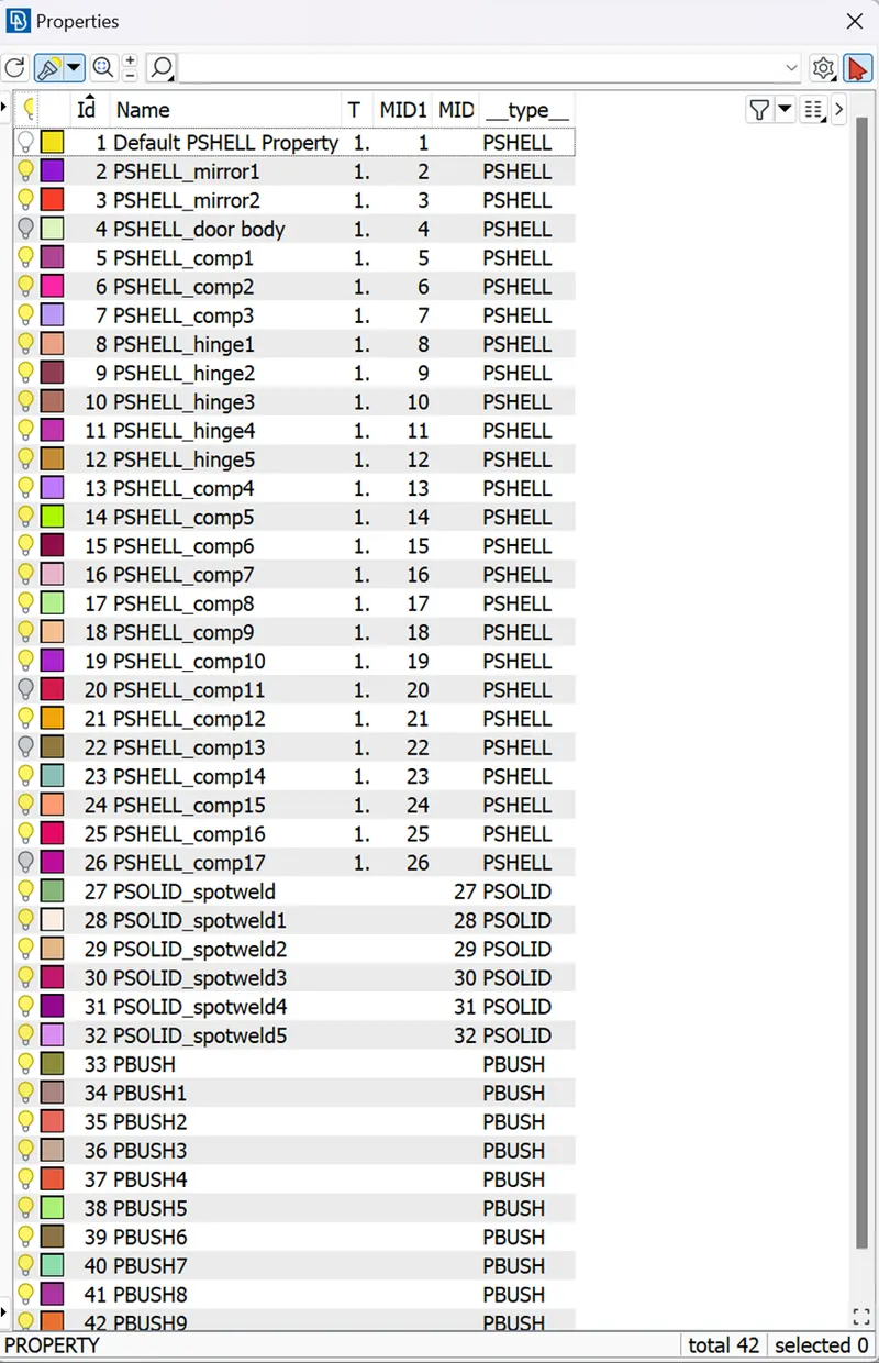
Now we can move onto deploying connections in between them
Different Types OF connections provided are as follows: -
1.Bolt
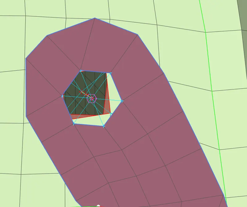
Bolt connections are rigid links used in hole location.Bolt is used to link adjacent FE components through edge nodes.
In ANSA,the COG point of a looped edge are converted into a bolt connection. First we will need to create COG points by selecting two edges we can do that using tool POINTS>ON COG>EDGES in TOPO module. The adjacent components are selected and given aFE type as BOLT in connection manager.
An appropriate search distance is given and the connection is realized.
Part where Bolt connection is provided is as follows,
- RBE2 and RBE3 elements:
RBE2 elements add infinite stiffness to the nodes being constrained. There is zero relative motion between the nodes of the RBE2, this connection type effectively rigidizes whichever portion of your model is included within the constraint.
Following image shows a Parts in geometry where RBE2 connections are provided
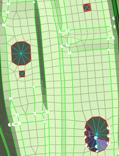
RBE2 elements are rigid 1D elements to transfer motion with one independent node and many dependent nodes used to model rigid connections.
RBE3 elements are rigid 1D elements to transfer motion with one dependent node and many independent nodes used to model rigid connections.
Various features or parts where RBE2 & RBE3 connections are provided are as follows: -
3.Door hinge:
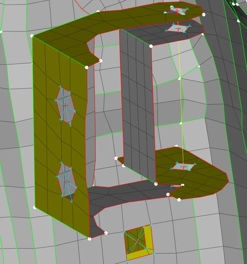
The door hinge connections are created with RBE2 cluster elements.
Command NASTRAN DECK>ELEMENTS>REB2 ELEMENTS
The sixth DOF is left free in order to move the door with respect to global Z direction
Following images shows a Door Hinge where different types of RBE2 Connections like REB2 Cluster, RBE2 two nodes RBE2 many nodes etc are deployed
4.Handle:
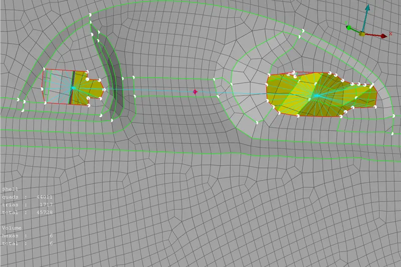
In this rear door model, the handle bar is represented with RBE2 elements.They are created by selecting the looped edges of the handle using the option ELEMENTS>RBE2 in Nastran deck.The master node of RBE2 elements is provided with a mass of 1e-4 tonnes(100 gms) using the option CONMi>CONM2>Nodes.
Following image shows door handle where REB2 connection is provided
5.Window:
The connections in window between the glass and weather beads are created by creating curves from the FE model of weather beads using the option FE2CURVE(feature to curve). First the curves are generated on respective edges of a window then those curves are converted into spot lines using convert option.
Curves generated and converted into spot lines are as follows
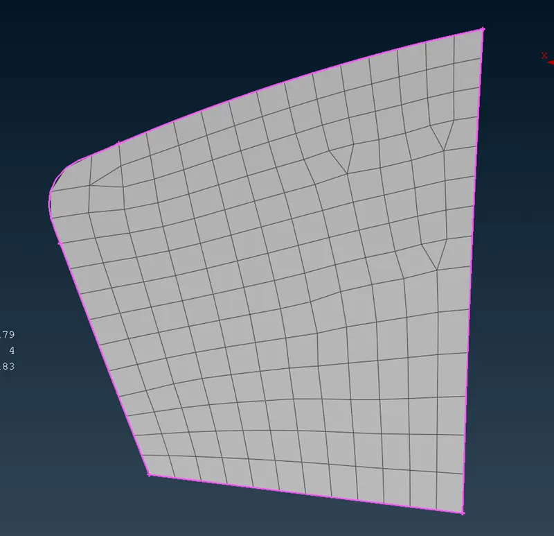
In the connection manager, the spot lines are selected for making connection between glass and weather beads. Curves are selected spacing is provided as 10 mm respective two properties are selected value of spacing is provided as 10 mm The glass and weather beads FE models selected and the connection representation is chosen as RBE3-CBUSH-RBE3.
PBUSH properties are created accordingly and the property IDs are entered in the connection manager list. RBE3 Pin flags represents DOF for the glass window in the smaller window all DOF are arrested as it is a non-moving or fix window. An appropriate search distance is given and the connection is realized.
Realized connection is as follows
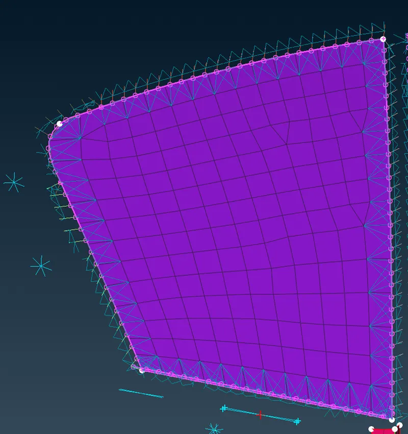
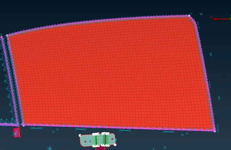
Same procedure is repeated for bigger window only difference there is that it is a moving window so REB3 pinflags or DOF there is provided based on the direction or axis or plane in which it will move upwards and downwards
Realized connection for bigger window is as follows
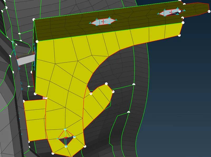
6.Spot weld
Spot weld connections are used in point location.
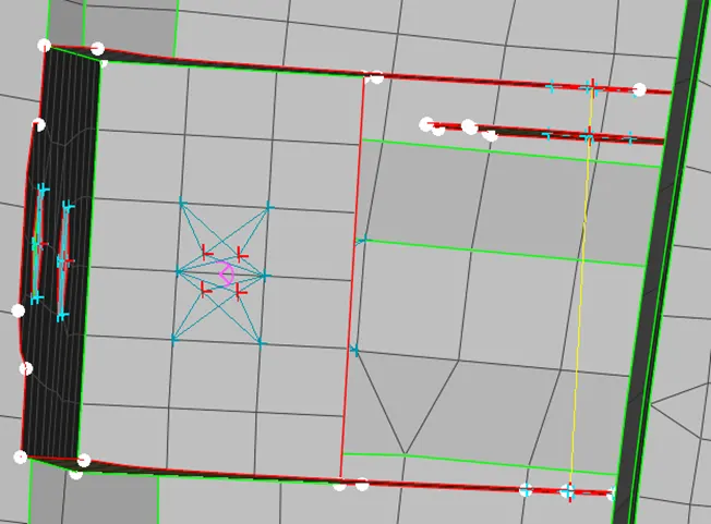
For connections involving spot welding, a suitable nodes are selected and it is converted into a spot-welding point.
The adjacent components are selected and given with FE type as RB3-HEXA-RB3 in connection manager.
A PSOLID property is created and the property ID is entered in that connection manager list.
An appropriate search distance is given and the connection is realized.
Realized spot weld connection looks as follows
Learning outcomes:
1.Bolt and spotweld connections are made.
2.Rigid body elements are linked.
3.Mass of handle is represented.
4.CBUSH elements are realized and aligned globally.
Conclusion:
Thus, various connections are created and realized using different connection techniques for the rear door FE model using ANSA.