Week - 5 - 2D meshing for Plastic components
Week - 5 - 2D meshing for Plastic components
Objective: To extract the mid surface and mesh the given bottle cap component using given quality criteria and assign correct thickness to the property.
|
S.No |
Quality Criteria |
Value |
|
1 |
Target/Average length |
1 |
|
2 |
Minimum Length |
0.5 |
|
3 |
Maximum Length |
3 |
|
4 |
Aspect |
3 |
|
5 |
Warpage |
15 |
|
6 |
Skewness |
45 |
|
7 |
Jacobian |
0.7 |
|
8 |
Minimum Quad Angle |
45 |
|
9 |
Maximum Quad Angle |
135 |
|
10 |
Minimum Tria Angle |
30 |
|
11 |
Maximum Tria Angle |
120 |
|
10 |
Tria Percentage |
15 |
Procedure: -
1.Importing CAD model into, given cad model looks as follows
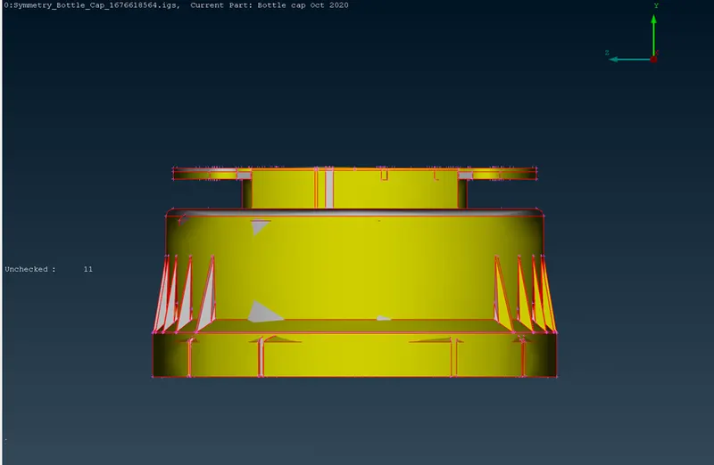
From single cons we can determine that the model is not properly stitched it also shows that there are several unchecked faces also in the model
2.First step is to Perform TOPO operation onto the model in order to stitch it properly for that command is FACES>TOPO in TOPO module after performing TOPO on the model model looks as follows
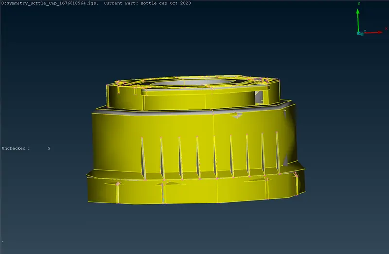
3.Next we have to assign given minimum target length to the model in this case it is 1 mm for this command is PERMIETERS>LENGTH in the classic mesh module
4.after that we have to check if there are any geometrical errors in the model or not for that we have to perform Geometry checks on the model for that the command is UTILITIES>CHECKS>GEOMETRY CHECKS
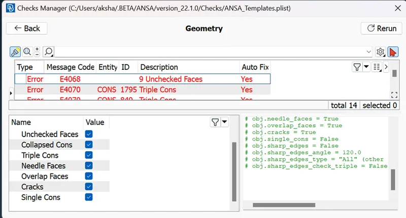
As we can see in the above image there are several errors in the model some of them we can auto fix some we have to remove manually
After removing the errors present in the model, checks manager window will look as follows with status as ticked
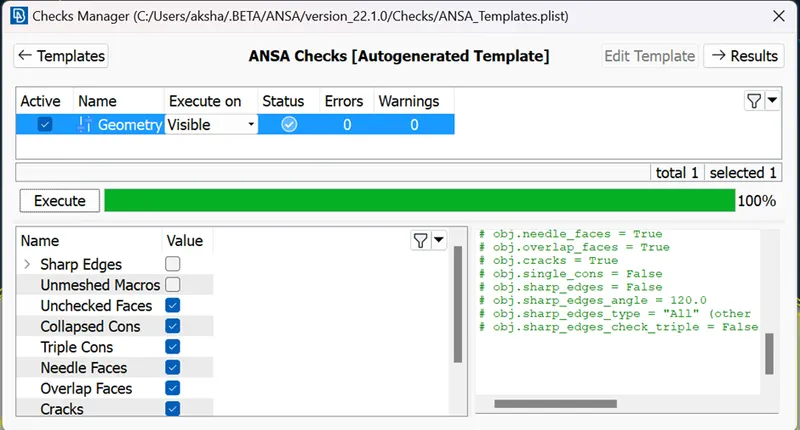
once again to release all the cons use command FACES>TOPO in TOPO module
Then FACES>ORIENT command is used to check the orientation is proper in all the faces of the CAD geometry.
5.Before extracting the Mid surface of the components, it is important to measure the thickness of the component in order to determine whether the component is sheet metal component or plastic component. For measuring thickness command used is UTILITIES>MEASURE. And by choosing the extreme end of two hot points we can measure thickness of the geometry.
After checking thickness, it is observed that model has various thickness across its different features
6.Next we have to extract the mid surface for the model
7.we can use not or I ‘not tools to separate the surfaces for taking midsurfaces.
8.First we will try and create midsurface for cylindrical base surfaces
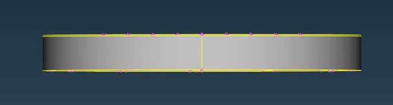
In the base surface to create its midsurface we will select its outer side/face as from inside it has various features attached to it
We will use FACES>OFFSET command for creating its midsurface and assign it a PID
Created midsurface will look as follows
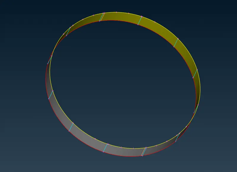
We will be providing same PID For all the midsurfaces captured
- Next we will create midsurface for cylindrical cone using same FACES>OFFSET command and assigning it the same common PID
In order to create midsurface for this cone we have to select its inner face as it has various features on its outer dia
The midsurface we will create it should be uniform and created midsurface will have have some gaps or it wont be uniform due the features present over it
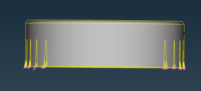
created midsurface will has some gaps so in order for it to be uniform we will create curves in between the gaps by using command CURVES>CREATE and connect them using command CURVES>CONNECT similar thing we will do for top surface after creating curves we will connect those curves and delete the previously created faces and again will create new surface in between the top and bottom curves
Created midsurface will look as follows
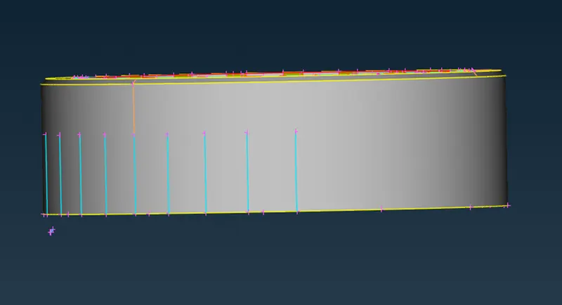
10.midsurface created for two cylindrical portions will look as follows
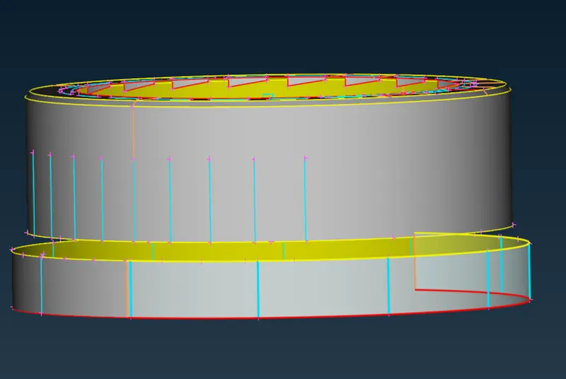
There is one gap in between those midsurfaces we will fill that gap by creating a new surface in between the two surface using command FACES>NEW
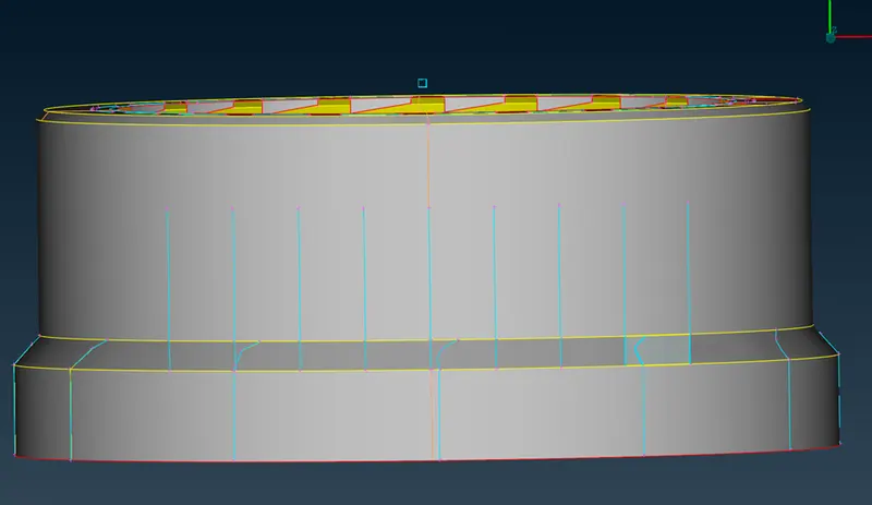
Then we will perform TOPO on the surface in order to stitch them with each other propely assigning it the same common PID
- similarly we will create midsurface for inner cylindrical sections assigning it the same common PID
- Here we have some threads in the bottle cap. it has trapezium shaped surface to get a exact mid surface we will use command FACES>MIDDLE
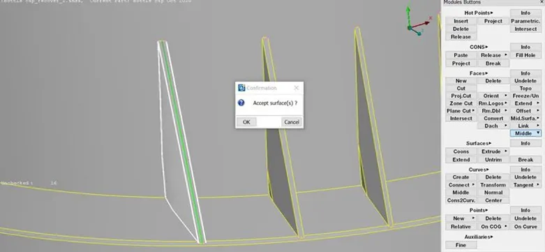
-
Simlirly we have to create midsurface for all the threads assigning it the same common PID
- Crated midsurface will looks as follows
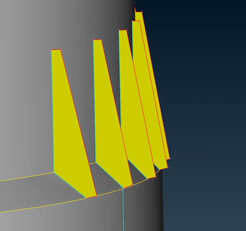
-
We have to extend the edges of the thread on the base and surface it is facing after that triple con connection will be formed between them
- we have some ribs having varying thickness in the inner bottom of the model.
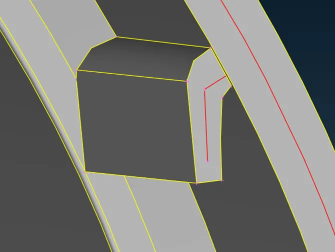
-
We can create midsurface for them using command FACES>MIDDLE. created surface will look as follows
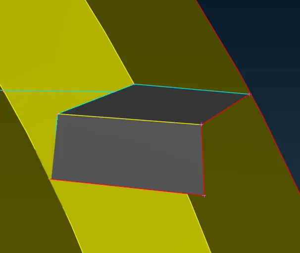
-
We have perform TOPO on that surface in order to stitch two faces with each other after that we have to extend those surfaces to the base and the surface it is facing
Similialry we can create midsurface for all the ribs assigning it the same common PID
-
next we have to create midsurface for all the tooth section inside
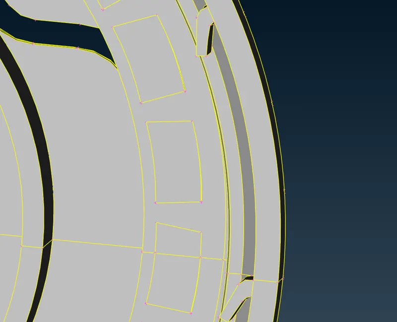
We will create midsurface for a single tooth and then we can transform that midsurface
To create midsurface for tooth we have to use FACES>MIDDLE Command
Now instead of creating midsurface for all the teeth separately we can transform the midsurface which we have created before on the base.
To transform the midsurface we have to create cog points around which it will rotate and transform
We will use command ON COG >EDGES and select two edges for two circles
Created two COG points will look as follows
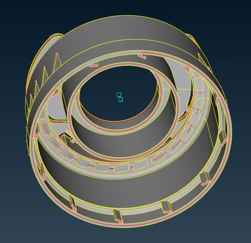
18.then to transform the midsurface which we have created before we can use command UTILITIES>TRANSFORM>COPY
We have to copy the midsurface of the tooth and middle click
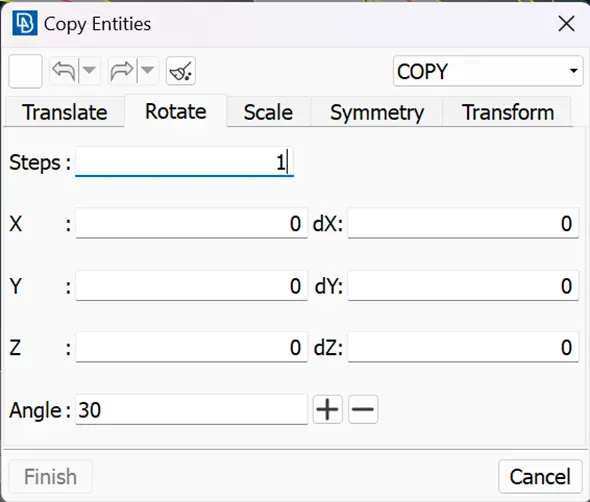
In steps we will put 21 steps as there are total 22 teeth and for 1 tooth we have already created midsurface
In the X we will select one COG point and in dx we have to select the other COG point angle we have to put as 360/22 ie. 16.36
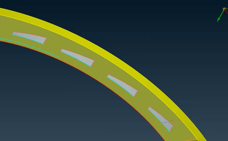
After clicking on + button and clicking ok midsurface is transformed and rotated on the base assigning it the same common PID
Rotated midsurfaces will look as follows
- similiarly we have to create midsurface for all the remaining features
-
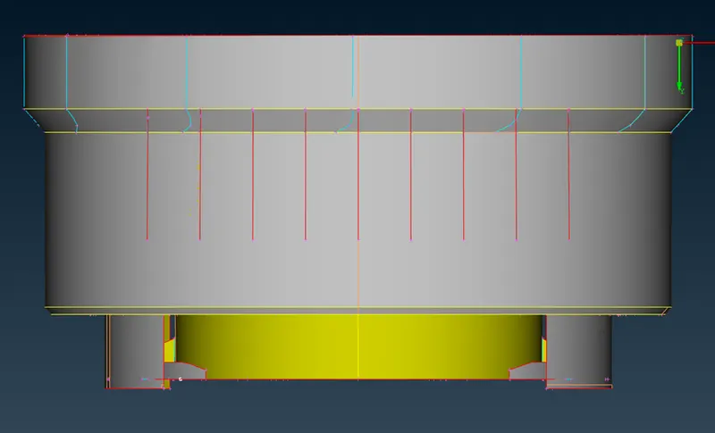
after creating mid surface and assigning them PID midsurface for whole geometry looks as follows
-
before proceeding to mesh the component we have to make sure that midsurface created for the features are properly extended on to the respective surfaces
-
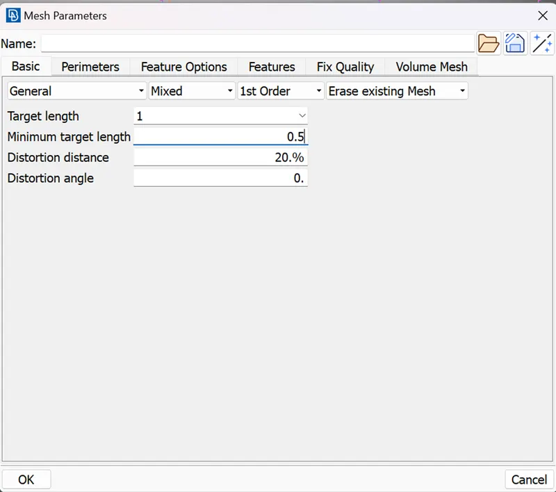
next we have to assign mesh parameters with min target length as 1 mm and mi length as 0.5mm
- next we have to assign the quality criteria for the mesh assigned quality criteria is as follows
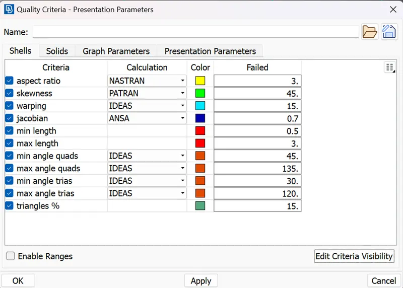
- given component can be meshed using the command MESH GENERATION>BEST MESH. After when all the defeaturing works are done, the complex component can be subdivided into smaller portions to obtain better quality mesh and that can be achieved by introducing cuts in between the parts we can use the command MACROS>CUTcommand and then meshing can be applied for the individual places. And hence the Mesh will be generated in the component.
-
In the mesh, the following things should be followed: -
1) The mesh should be smooth and clean
2) Back-to-Back trias should be avoided
3) Tow opposite trias nearer to each other should be avoided
4) Tria elements in the fillets should be avoided
5) Tria elements in adjacent to outer edges should be removed
6) Tria elements attached to the hole edges should be avoided
So, after obtaining the mesh, the above things to be taken care and the tria elements can be mostly avoided by using the following commands: -
Elements ---> Split, Elements ---> Swap, Grids ---> Paste These commands are used to move the trias forward and backword and also to split them. Elements ---> Join command is also used to reshape many tria elements and by using these commands we can achieve the above conditions and the tria elements can be avoided.
Shell mesh ---> Reconstruct and Shell mesh ---> Smooth commands are also used to obtain the smooth elements in our meshed model.
And hence, when our meshes are failing to fill the quality criteria provided, they can be cleared with the help of the above steps and commands provided.
Meshed model looks as follows
There are some off elements present in the model we will keep them as it is as they can not be removed
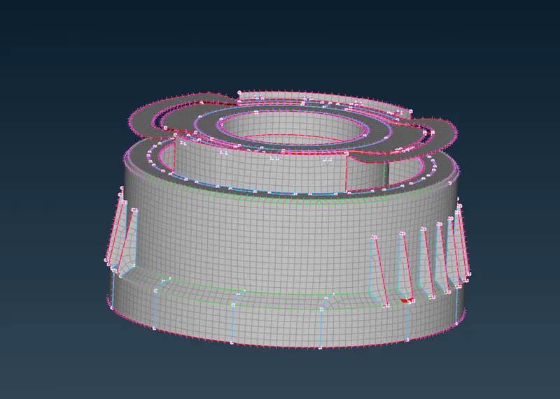
-
After meshing we have to recheck if the thickness for the midsurface is provided or not. As we have created a common PID for all the components we have to provide separate PID for all the components according to their thickness. After that we have to draw the shells as solids for that we can use command UTILITIES>QUALITY CRITERIA>PRESENTATION PARAMETERS>DRAW SHELL AS SOLIDS
Conclusion:
Geometry clean-up, mid surface extraction, and 2D meshing of the given model were successfully done. All the features in the model are captured properly with good mesh flow. Tria concentration is kept low.
- we have some ribs having varying thickness in the inner bottom of the model.