Week 4 - 2D Meshing for Sheet Metal
QUESTION: -
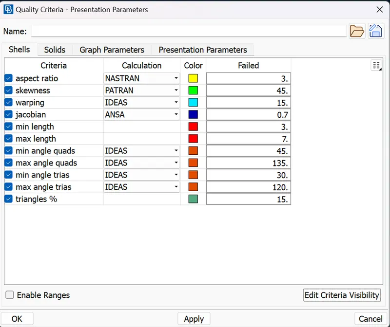
For the given CCB CAD model, Check for the Geometry cleanup (if required), Take the mid surface, and Mesh it with the below 2D element Quality criteria.
| SR NO | QUALITY CRITERIA | VALUE |
| 1 | TARGET/AVERAGE LENGTH | 5 |
| 2 | MINIMUM LENGTH | 3 |
| 3 | MAXIMUM LENGTH | 7 |
| 4 | ASPECT | 3 |
| 5 | WARPAGE | 15 |
| 6 | SKEWNESS | 45 |
| 7 | JACOBIAN | 0.7 |
| 8 | MINIMUM QUAD ANGLE | 45 |
| 9 | MAXIMUM QUAD ANGLE | 135 |
| 10 | MINIMUM TRIA ANGLE | 30 |
| 11 | MAXIMUM TRIA ANGLE | 120 |
| 12 | TRIA PERCENTAGE | 15 |
PROCEDURE:-
1.First to open the cad geometry in the ANSA software, after opening we will notice that the geometry is as follows
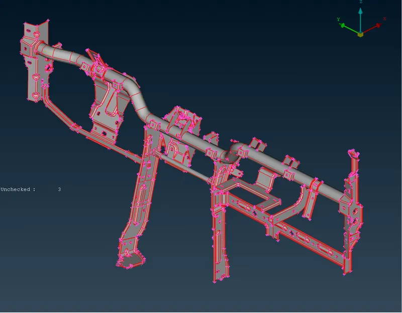
2.As it shows in the image, the geometry is unchecked and it has all the red cons(single cons) which means that the geometry is not stitched or the parts are not stitched together and in order to stitch them we will first perform TOPO operation on the model which can be done using FACES>TOPO tab available in the TOPO module
3.After performing the TOPO operation geometry is stitched together and it looks like as follows
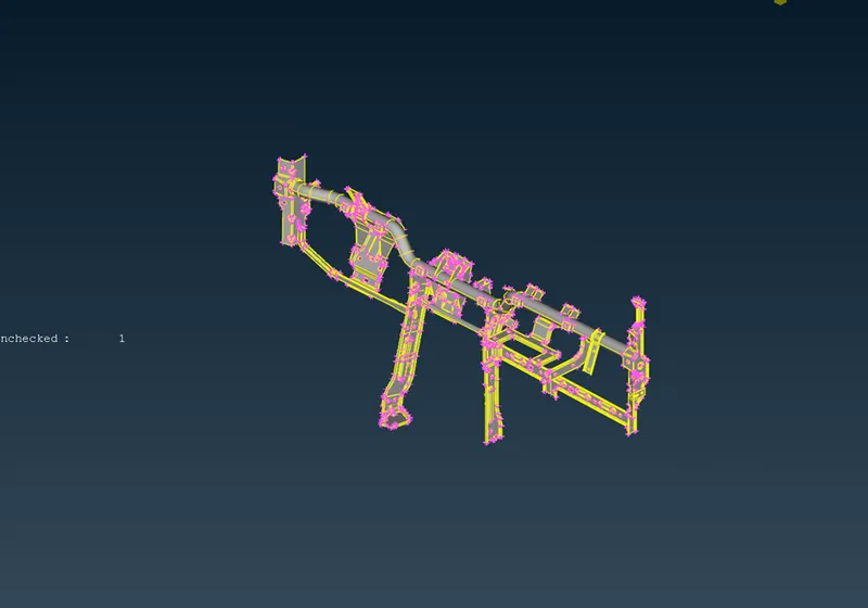
3.Next step is to assign the given target element length to the component,in this case it is 5mm.we can assign length to the component using PERIMETERS>LENGTH option available in the classic mesh module
4.Next we have to perform geometry check operation on the model in order to find out if there are geometrical errors like unchecked faces, needle faces, cracked elements, triple cons etc are present, in order to remove them and refine the geometry. We can perform geometry check on the given model using CHECKS>GEOMETRY tab available in the TOOLS section
5.After performing the geometry check onto the model we can observe errors (if present any) as follows
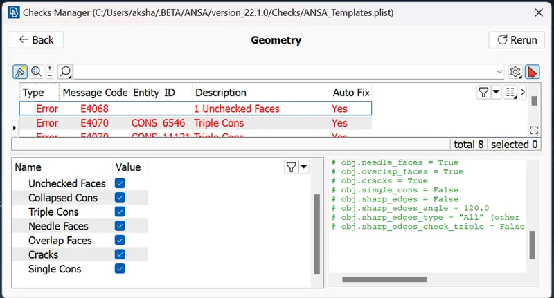
To refine the geometry, we have to remove these errors. Errors can be removed by using auto fix option and some are to be removed manually
6.after removing the errors we have to recheck if there are any errors left to be removed or to correct. After geometry check we found out that there are no errors present and status as checked as per the following image
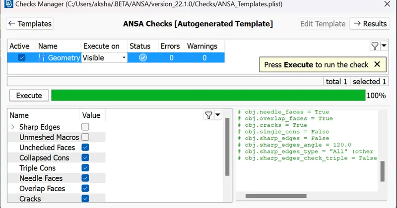
7.After removing the errors we have to check whether the component is of uniform thickness or not
8.After checking we found out that the component is of non-uniform thickness, we checked thickness for different components and stored those measurements
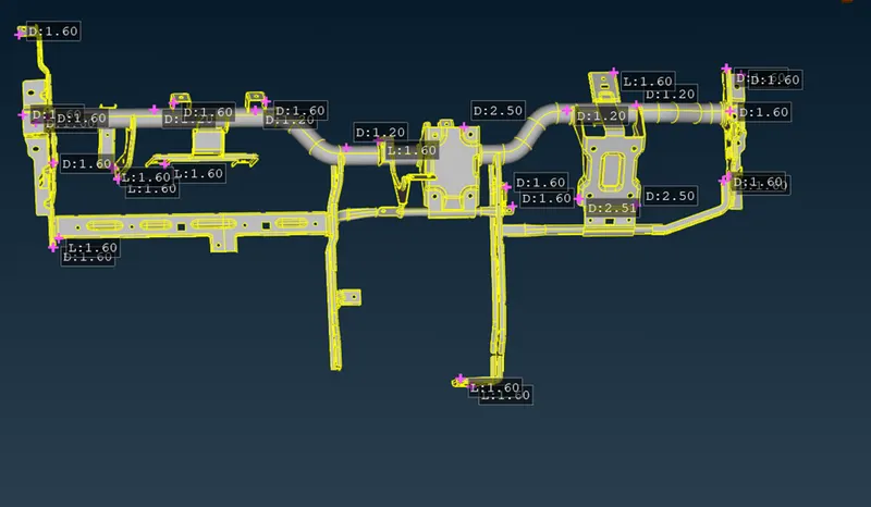
9.after checking we found out that the geometry various different PID’S are assigned to the geometry first we will select the whole component and provide a separate PID to the whole geometry in order to distinguish it more accurately
10.Next step is to generate the midsurface.as here the thickness is non-uniform we have to generate mid surface for components individually and provide them the PID as per their thickness
11.for generating mid surface we can use FACES>MIDSURFACE>SKIN option present in the TOPO module
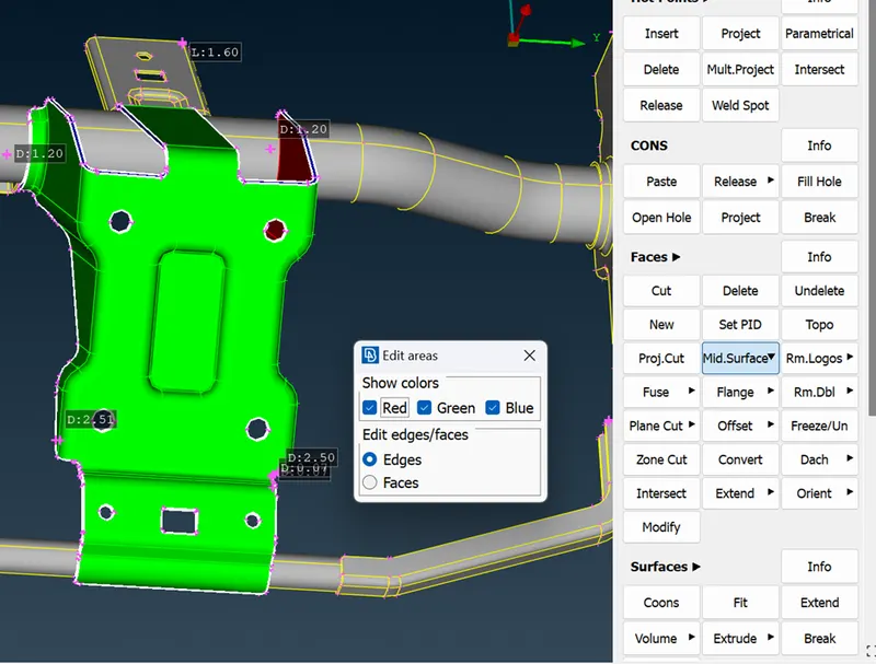
12.we selected and generated midsurface for different components and provided PID’S according to their thickness
13.Mid surface of the whole geometry looks as follows and the image also shows the PID’S provided to them as per their thickness
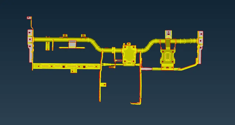

14.This geometry has four different thickness values for its various components. Components with similar thicknesses are included in the same PID. thickness to the midsurfaces is also assigned as per their thickness in the parent geometry
15.Then we can move onto meshing the component but before that we will need to assign quality criteria and mesh parameters with the values given in the question
16.first we will assign mesh parameters as follows. Mesh parameters are assigned from UTILITIES>MESH PARAMETERS
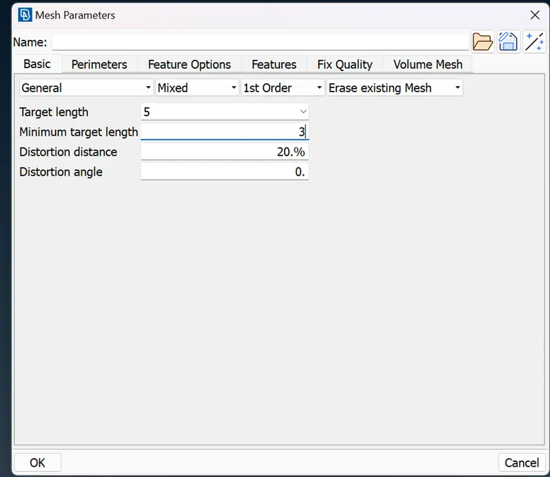
Target length of 5mm and minimum length as 3 mm are assigned as per instructions
17.Then we will assign the quality criteria to the given model as per instructions. Assigned quality criteria is as follows. We will also save the following quality criteria for future reference if needed.quality criteria is assigned from UTILITIES>QUALITY CRITERIA
18.Then next step is to mesh the component to qualify for the given quality criteria and mesh parameters.
19.Component is mesh using MESH GENERATION>BEST MESH in classic mesh module
20.After meshing in hidden mode we can see the areas where mesh is failing or if any off elements are present after meshing. These off elements are to be removed using various tools available in mesh module
21.Surface to be meshed is cut into proper sections in order to achieve good mesh flow and to reduce off elements
22.We can remove these cuts and also be able to keep the original mesh using join tool
23.In order to get good mesh flow Make sure to create a zone cut around all bolt holes
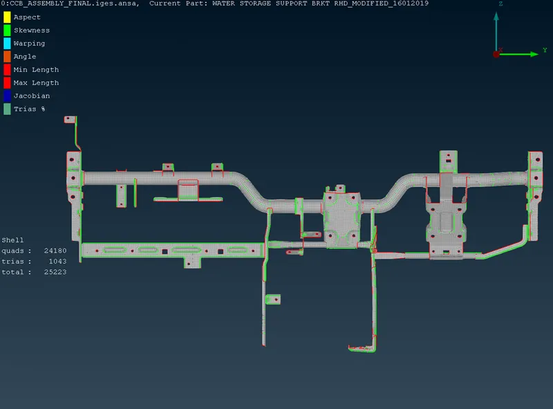
24.Properly meshed component qualifying for quality criteria without any off elements is as shown below
25.After meshing the component recheck whether thickness is assigned to the created PID’S if not then assign thickness and then draw shell as solid using UTILITIES>QUALITY CRITERIA>PRESENTATION PARAMETERS>DRAW SHELL AS SOLID
RESULT: -
1.The geometry was cleaned and mid-surface was generated.
2.The mid-surfaces were meshed and thickness was applied.
3.Good Mesh flow around intricate areas was achieved
LEARNING OUTCOMES: -
1.The problems encountered.
2.Mid surface generation for components with varying thickness
3.Learnt Using cut tool, Num (+/-), slide tool options
CONCLUSION: -
Geometry clean-up, mid surface extraction, and 2D meshing of the were successfully done. And all the elements pass the quality criteria. All the features in the model are captured properly with good mesh flow. Tria concentration is kept low.