Week 9 Challenge
Report on Creating Sliders & Inserts for a CPU Fan Case Mold in SolidWorks
This report details the procedure for creating sliders to accommodate complex geometries in a pre-designed CPU fan case part. Sliders are essential for molding features that cannot be formed by the main core and cavity pull direction. This document outlines the steps for designing and implementing sliders in the mold assembly.
1. Identify Areas Requiring Sliders & Inserts
1. Examine the Part:
- Open the provided CPU fan case part in SolidWorks.
- Identify
undercuts, side features, and other geometries that cannot be molded using
the main core and cavity separation. Common areas include:
- Snap-fit hooks or clips.
- Side vents or intricate cutouts.
- Features extending perpendicular to the main mold opening direction.
2. Design the Sliders & Inserts
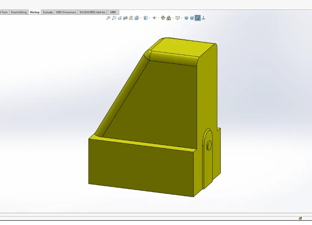
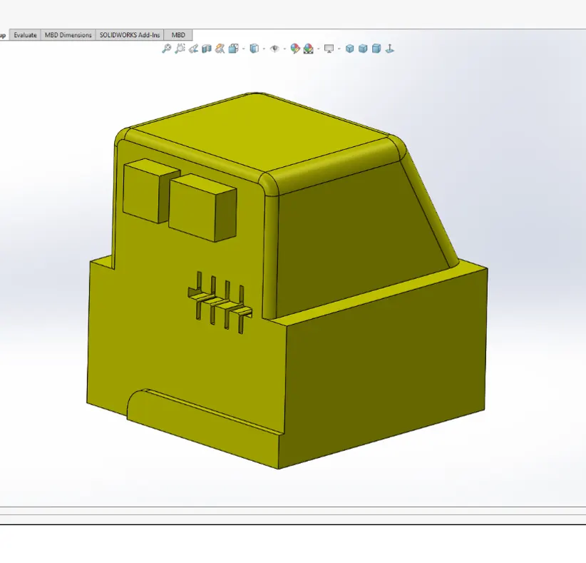
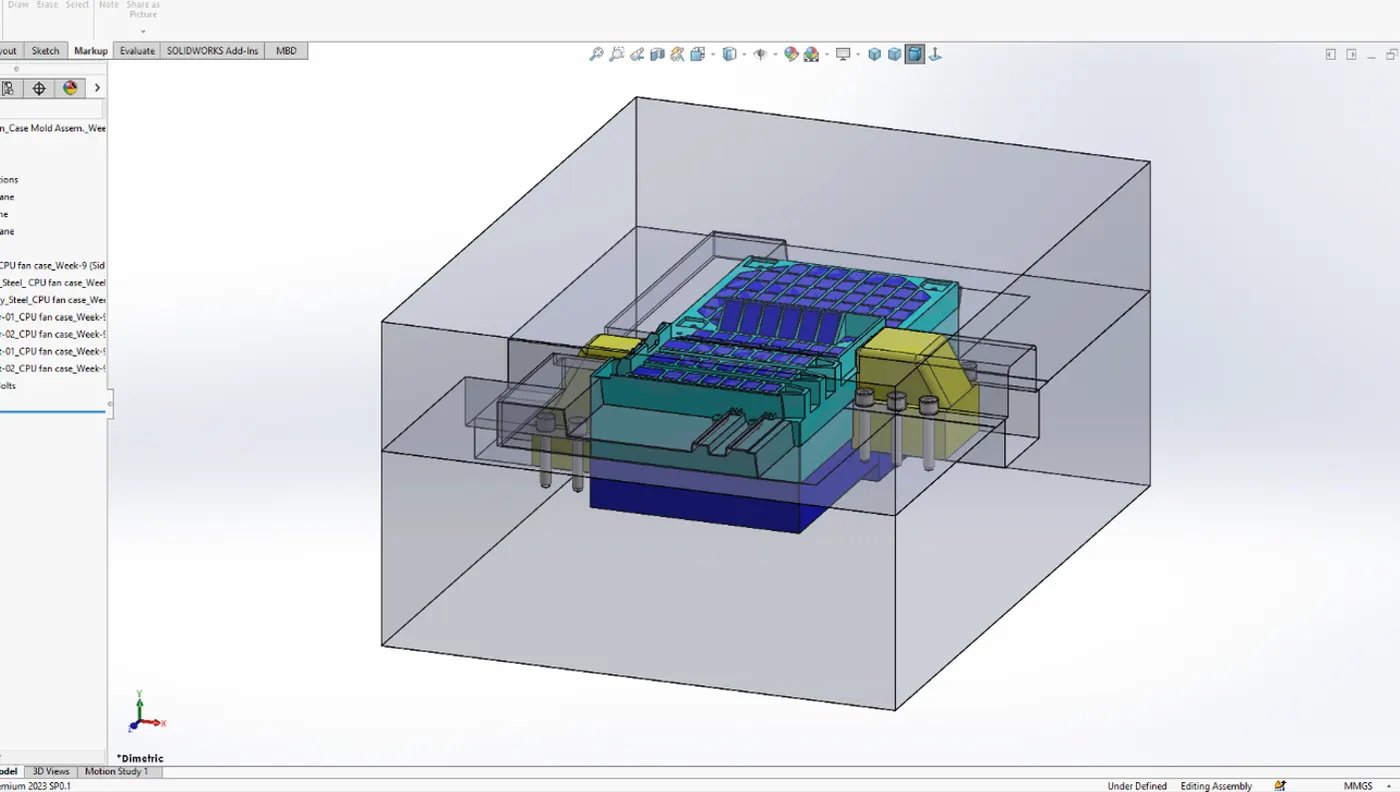
1. Create Slider Geometry:
- Sketch
the Slider Profile:
- Create a sketch on the parting line plane or an appropriate plane that aligns with the undercut features.
- Draw the profile of the slider, ensuring it encompasses the undercut areas. - Extrude
the Slider:
- Use the 'Extrude Boss/Base' feature to extrude the sketch and form the slider body. Ensure the extrusion length is sufficient to clear the part during mold opening.
2. Add Guide Features:
- Guide
Rails:
- Add guide rails to the slider and the mold base using the 'Extruded Boss/Base' feature. These rails will ensure the slider moves in a controlled path. - Angle
Pins:
- Use the 'Hole Wizard' to create angled holes for angle pins. Angle pins guide the slider movement during the mold's opening and closing cycles.
3. Implement Sliders & Inserts in the Mold Assembly
1. Create a New Assembly:
- Open a new assembly file in SolidWorks ('File > New > Assembly').
2. Insert Slider Components:
- Insert
Core and Cavity Blocks:
- Insert the core and cavity blocks into the assembly. - Insert
Sliders:
- Insert the designed slider components into the assembly.
- Position the sliders relative to the core and cavity blocks using the `Mate` feature to ensure correct alignment.
3. Add Guide Mechanisms:
- Guide
Rails:
- Add the guide rails to the assembly. Use mates to align the guide rails with the sliders and mold base. - Angle
Pins:
- Insert angle pins into the assembly. Use the `Mate` feature to position the angle pins in the pre-designed angled holes.
4. Simulate Slider Movement:
- Use the `Motion Study` tool or manually drag components in the assembly to simulate the slider movement. Ensure that the sliders move smoothly without interference and fully clear the part during mold opening.
4. Verification and Adjustment
1. Interference Detection:
- Perform interference detection ('Evaluate > Interference Detection') to ensure no parts interfere during slider movement.
2. Adjust Slider Dimensions and Mechanisms:
- Make necessary adjustments to slider dimensions, guide rails, and angle pins to ensure optimal performance. Ensure the sliders retract smoothly and do not cause defects in the molded part.
5. Finalize the Mold Design
1. Create Detailed Drawings:
- Generate
detailed 2D drawings of the sliders, core, cavity, and mold assembly
(`File > Make Drawing from Part/Assembly`). Include:
- Dimensions and tolerances.
- Material specifications.
- Detailed views of the slider mechanisms.
2. Assembly Instructions and BOM:
- Create comprehensive assembly instructions and a bill of materials (BOM) for all mold components, including sliders and their guiding mechanisms. Ensure all parts are clearly labeled and described for manufacturing and assembly.
Conclusion
Creating sliders for a CPU fan case mold in SolidWorks involves careful planning and design to address complex geometries that cannot be molded with a simple core and cavity separation. By identifying areas requiring sliders, designing the slider geometry and guide mechanisms, and thoroughly verifying their movement and function, you can ensure the mold will produce high-quality parts without defects. Proper documentation, including detailed drawings and assembly instructions, is crucial for successful manufacturing and assembly.