Week 9-Challenge
CONNECTORS & DEBUGGING
AIM:
The main aim of this challange is to learn various techniques for creating connectors like weld, adhesives, bolt etc..
INTRODUCTION:
Connectors are the entities that define the connection between two surfaces. They represent connections like weld or adhesives in hypermesh.
TYPES
1.Seam - Connects along length
2.Spot - Connects a point
3.Bolt - Connects two holes
4.Area - Connects by area (Eg: Adhesive)
5.Apply Mass
PROCEDURE:
SEAM CONNECTOR:
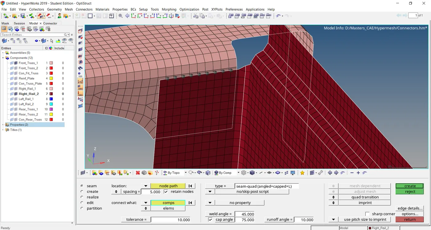
1) Select Connectors from 2D panel.

2) Select the seam option.

3) Select the nodes and the two components between which seam weld have to made. Weld angle should be 45 degree and cap angle and run off angle is industry specific, so I considered 75 and 10 degree respectively.
4) Select the type as Seam-quad(angled+capped+L) and hit create button. Spacing should be equal to element size & gve tolerance search value as 10mm.
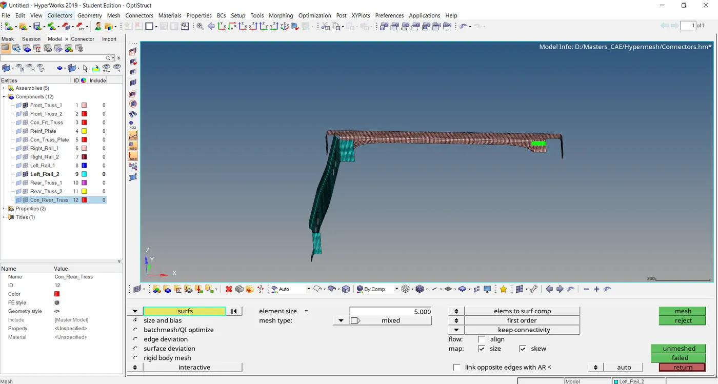
5) For Quad elements, select the type as quads.

6) The below figure depicts the quads element between Front truss 1 and Left Rail 2.
SPOT WELD CONNECTOR:
1) Select Spot option from 2D pannel.

2) Select the nodes and the components in which spot weld of dia 5mm with 3 layers have to be made. Make sure the tolerance is 10.

3) The below figure depicts the spot weld with 3 layers and 5mm in dia between Front truss 1, Front truss 2 & Left Rail 2.
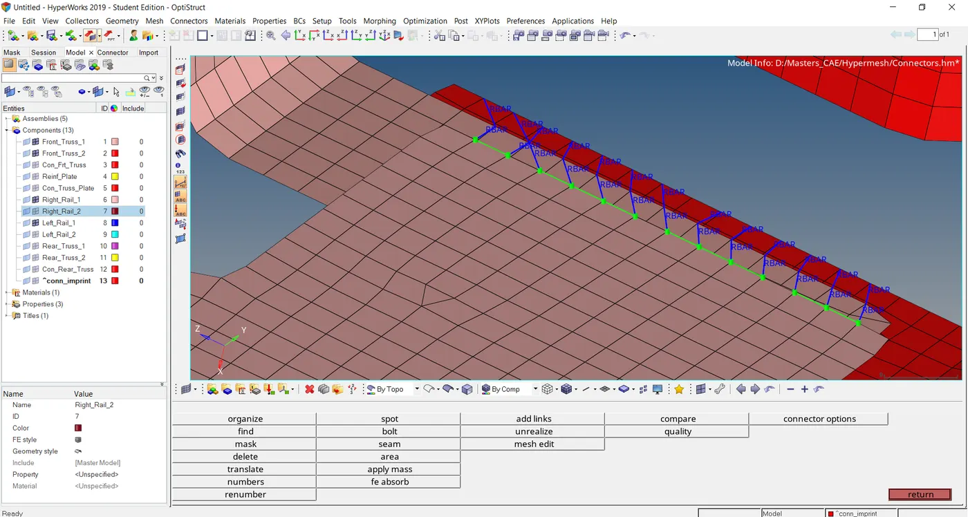
4) For rigid elements of spot weld, select the type as rigid and simply create hit button.

5) The below figure depicts the spot weld with rigid elements between Right rail 1 & Right Rail 2.
6) Similarly select type as spring element spot weld with spring elements.

BOLT CONNECTOR & ADHESIVES:
1) Select bolt option from 2D pannel.

2) Select the nodes of two components, between which bolt has to be connected and hit create button.

3) Bolt can be made only if hole exists on the surface of mesh. If not, there are cases as shown below to utilize for bolt connectors (Create hole, if none).

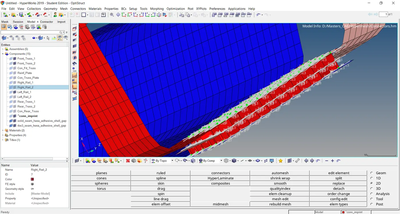
4) For hexa adhesive, change the type to hexa adhesive and in addition to that, also add how many coats and strips we want.

5) The below figure represents the hexa adhesive between Left rail 1, Front truss 1 & Front truss 2.
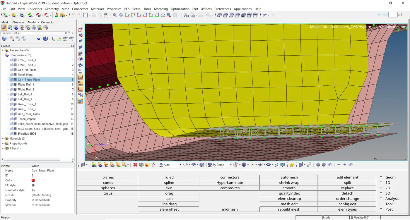
6) Here I change the type to bush of 5mm dia for the spot weld.

7) The below figure represents the spot weld with bush element.
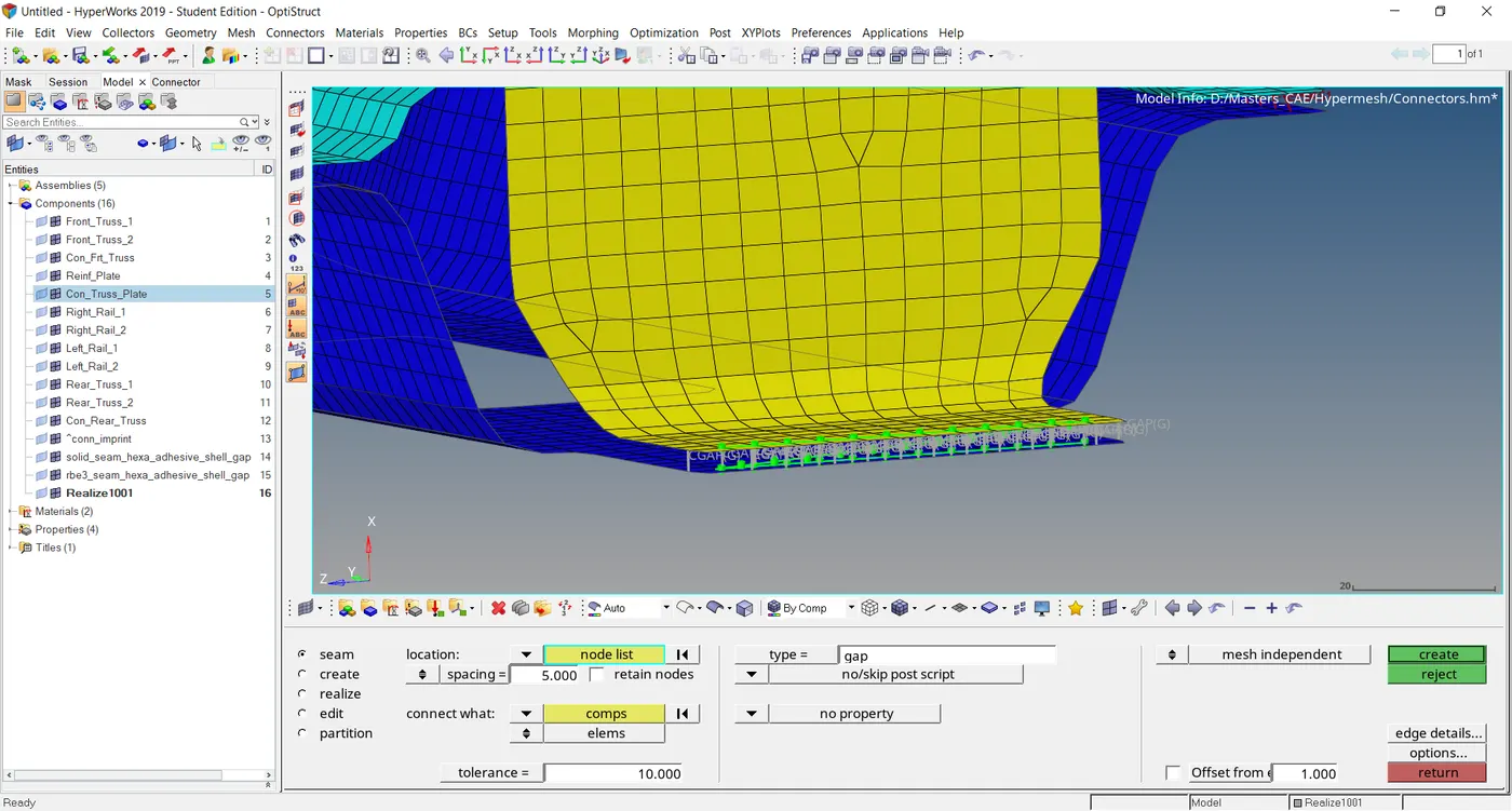
8) For rear truss 2 & Left trial 1, seam weld with gap element is made as connector.
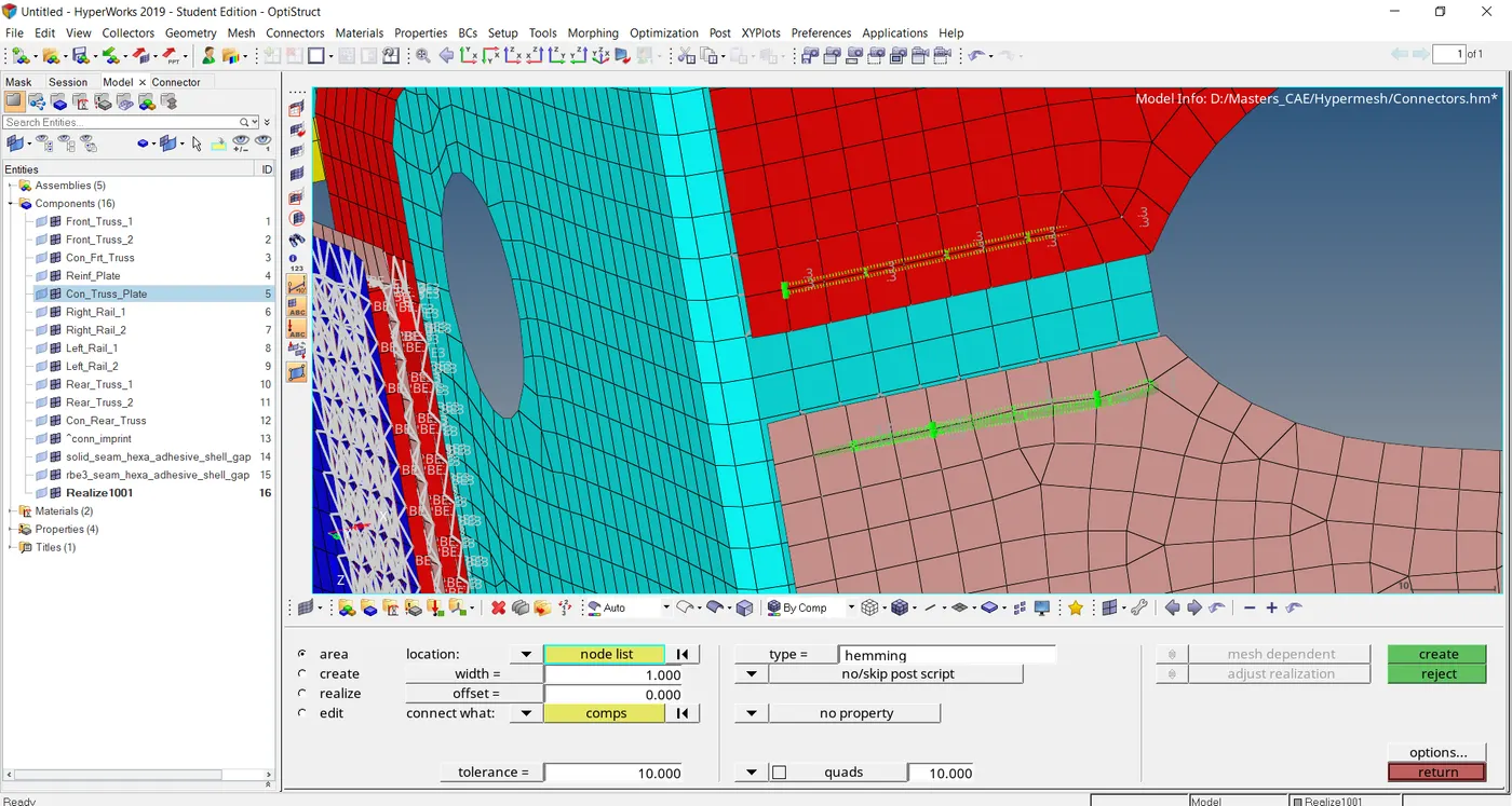
9) The below image represents the area connector with hemming type between Front truss 1, Front truss 2 & Left Rail 2.
RESULT:
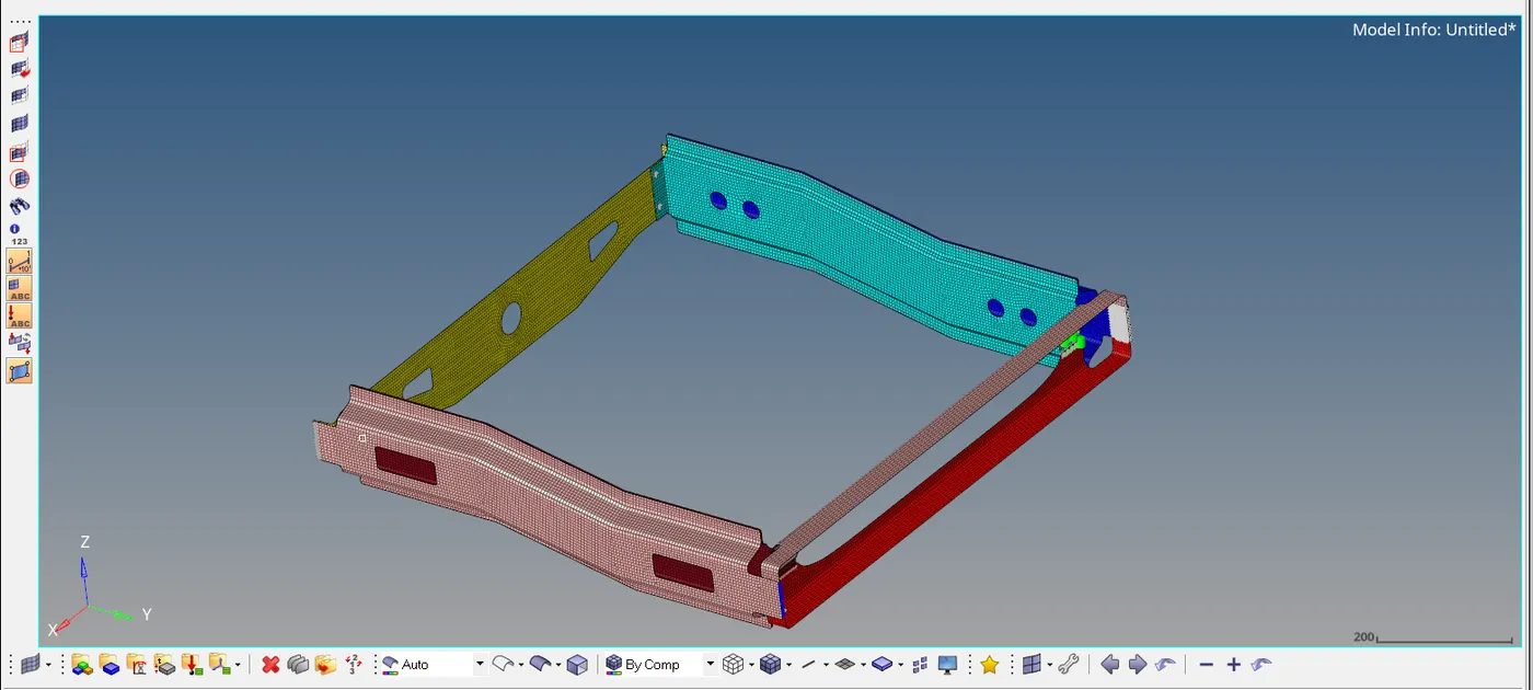
The various connectors made in the Assembly Frame assembly are:
1) Spot weld with rigid & spring element & bush.
2) Seam weld with adhesive & Quad elements & gap elements.
3) Area with hemming type elements.
CONCLUSION:
Thus the various technique of creating connectrs has been studied by this callange.
LOCATION FOR THE MODEL:
https://drive.google.com/file/d/1N1FaH1cFy0dSgeGUoX2-iswAUJXoKMmL/view?usp=sharing