Week 9-Challenge
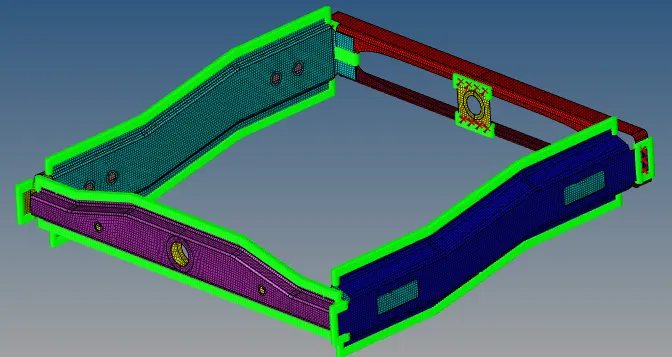
Objective: To connect components of model using different types of connectors.
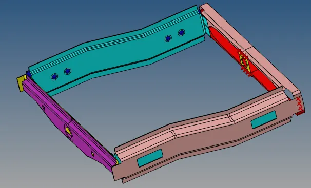
CAD File:
Procedure:
1) Import CAD File
File – Import – Model – Insert
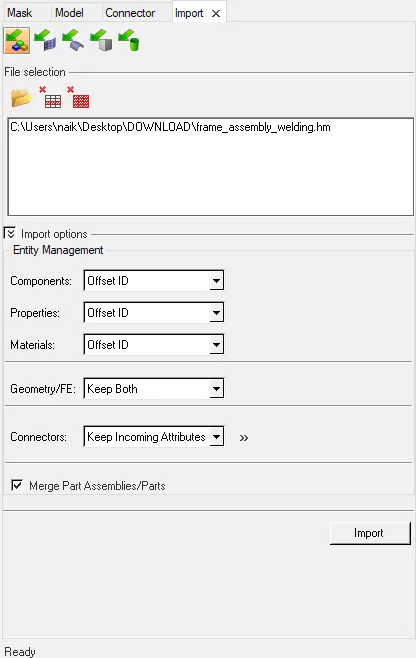
As per given problem statement we have to connect different components using connector options.
Create connector and Attach the various parts of the given model
- Right_Rail_2 & Front_truss_1:- Seam-Quad(angled+capped+L)
- Left_Rail_2 & Front_truss_1:- Quad elements
- Front_truss_2, Front_truss_1 & Right_Rail_1:- Spot weldwith 3 Layers and 5 mm Diameter
- Front_truss_2, Front_truss_1 & Left_Rail_1:- Hexa (Adhesive)
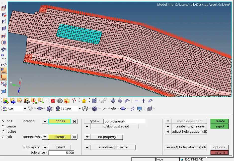
- Rear_truss_2 & Right_Rail_2:- Bolt Connector
- Rear_truss_2 & Left_Rail_2:- Bolt Connector
- Right_Rail_1 & Right_Rail_2:- Spot-weld with Rigid Elements
- Left_Rail_1 & Left_Rail_2:- Spot-weld withSpring Elements
- Rest all the component left Join them with suitable connectors
2) Generate 2D mesh and Check the Quality of mesh:
i) Generate 2D mesh
Changing meshing criteria to meshing size as 5 mm, minimum length of 3 mm and maximum length of 7 mm.
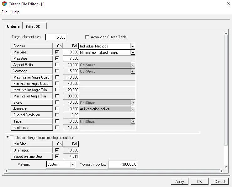
Auto mesh the given component by using element size as 5 mm and element shape as mixed.
F12 – Select Surface – Mesh
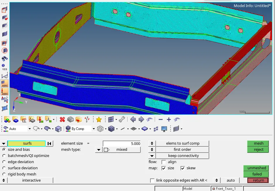
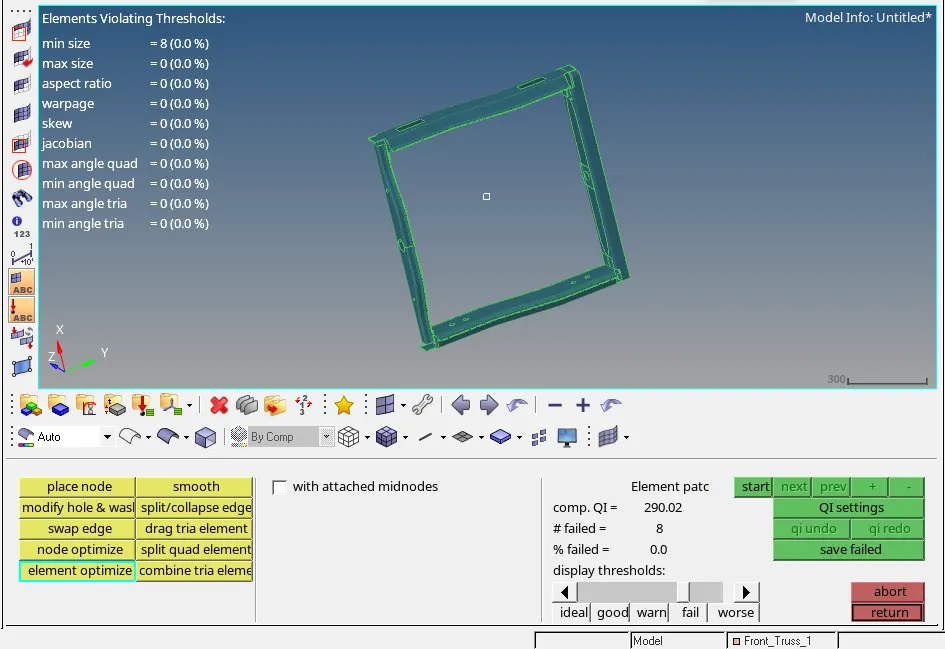
ii) Check the Quality of the elements and manually cleanup the failing elements.
2) Connecting the components using different connectors.
Connectors:
connectors are FE representation of some manufacturing joining process like welding , riveting , bolts etc.
Connectors are also used to connect two components with different element specification.
While creating connector we have to create new component for differnet types of connector.
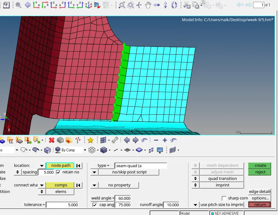
- Right_Rail_2 & Front_truss_1:- Seam-Quad ( angled + capped + L)
1D – Collector – Seam – Seam Quad (angled + capped + L) - Create
Set weld angle as 45, spacing as 5mm
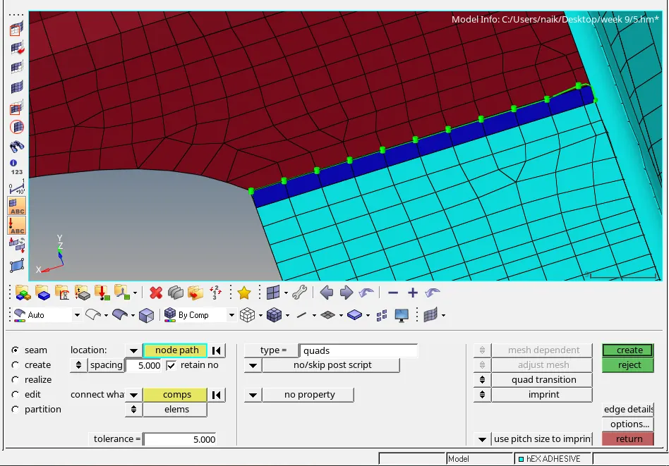
- Left_Rail_2 & Front_truss_1:- Quad elements
1D – Collector – Seam –Quad - Create
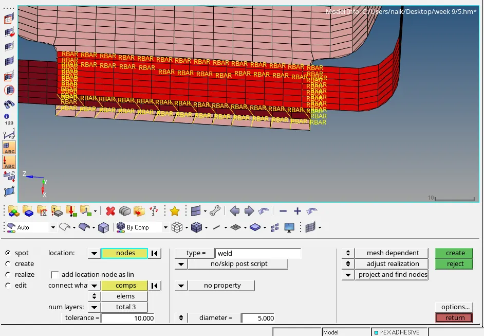
- Front_truss_2, Front_truss_1 & Right_Rail_1:- Spot weldwith 3 Layers and 5 mm Diameter
1D – Collector – spot – Create
As the connector is joining three surface used number of layer option as 3 layer and diameter as 5 mm.
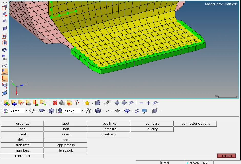
- Front_truss_2, Front_truss_1 & Left_Rail_1:- Hexa (Adhesive)
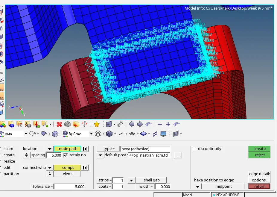
1D – Collector – Seam –Hexa (Adhesive) - Create
As the element length is 5 mm it is recommended to keep the width of 5mm.
- Rear_truss_2 & Right_Rail_2:- Bolt Connector
1D – Collector – Bolt - Create
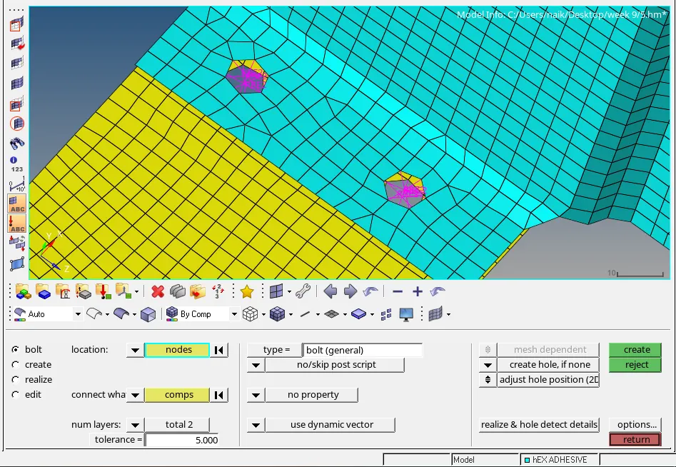
After creating the connector in some region remeshing is required.
- Rear_truss_2 & Left_Rail_2:- Bolt Connector
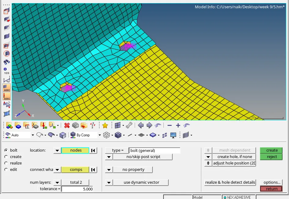
1D – Collector – Bolt - Create
- Right_Rail_1 & Right_Rail_2 :- Spot-weld with Rigid Elements.
1D – Collector – spot – Rigid Elements - Create.
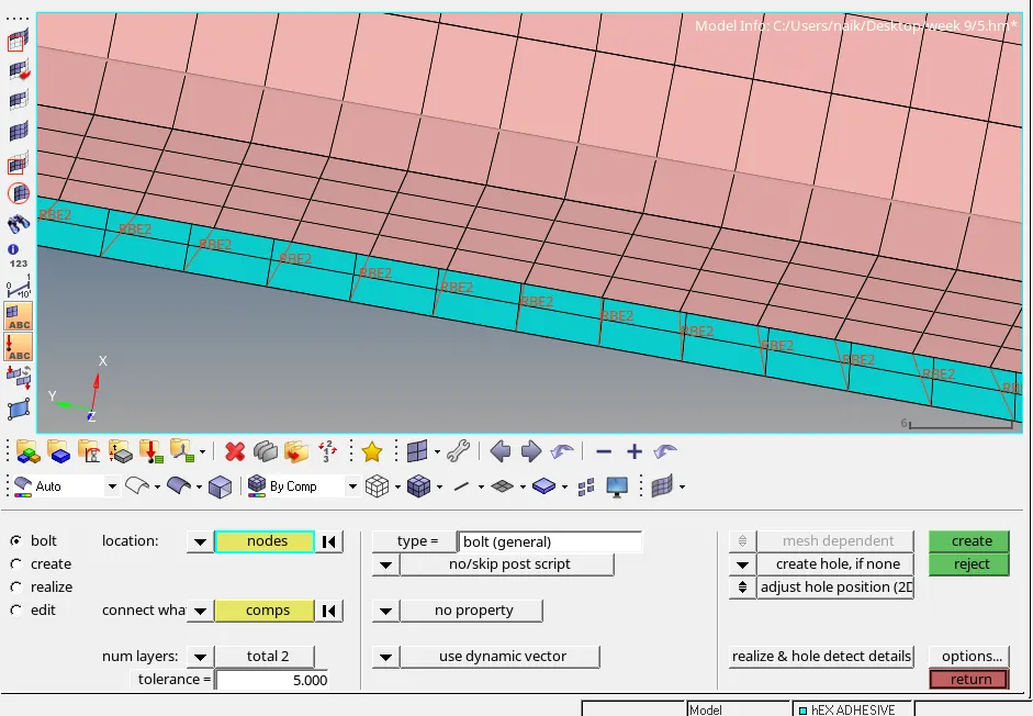
- Left_Rail_1 & Left_Rail_2:- Spot-weld withSpring Elements.
1D – Collector – spot – Spring Elements - Create.
- Rest all the component left Join them with suitable connectors.
Front truss 1 and front truss 2 with Reinf plate.
Spring as while appling load in we require minimum stress transfer to the inner body.
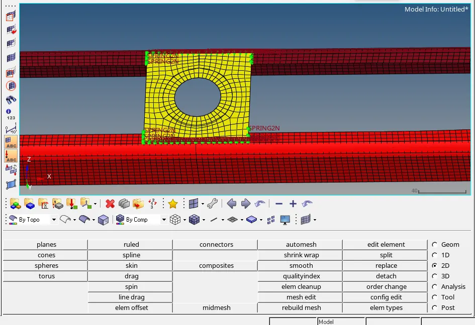
10. Front Truss 2 and right rail 2.
Hex adhesive elements adhesive welding is mostly used to eliminate joints like nails, rivets, screws or bolts.
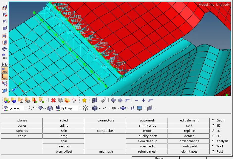
11. Rear truss 1and rear truss 2.
Rigid spring elements.
Should absorb some shock waves and also resist from wear and tear.
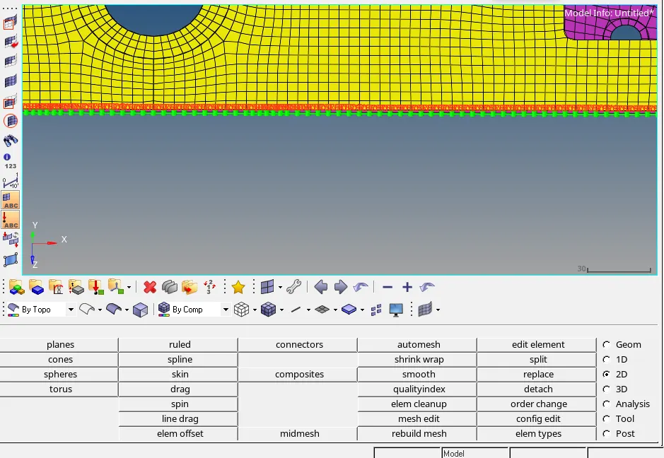
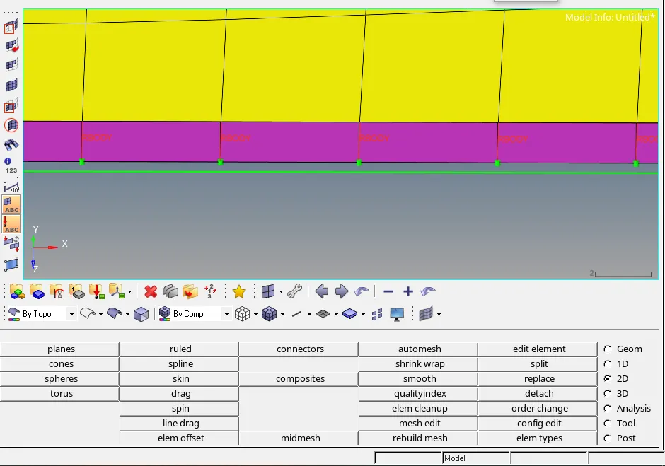
12) Right Rail 1 and Right Truss 2
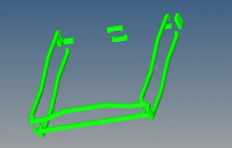
All Connectors
Conclusion :
1) Got to know how to connnect the component using different connector types.
2) It head me to know which connector type to use in differnt conditions.
3) Got knowledge regarding realizing and how to detect and eliminate failing elements.
Final Model: