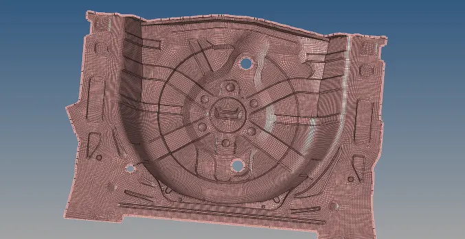
Project 2
Objectives:
- To generate the middle surface as well as geometric clean-up of the car side door.
- To generate a mesh and check the quality parameters of the elements.
- To assign thickness together with properties for the component of the side door of the car.
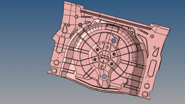
CAD file:
Procedure:
Being a CAE Engineer, one has to categorize the given part into multiple components as the geometry is in complex shape. As most of the surface is symmetric in Y-axis we can easily reflect the mesh over a point to reduce the meshing time.
Following is the procedure to classify the various components:
- To split the surface as required:
This tool is mostly used to split the part into two different surfaces.
- Geometry – surface edit – with points.
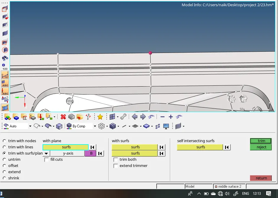
Select the base point and axis to the normal.
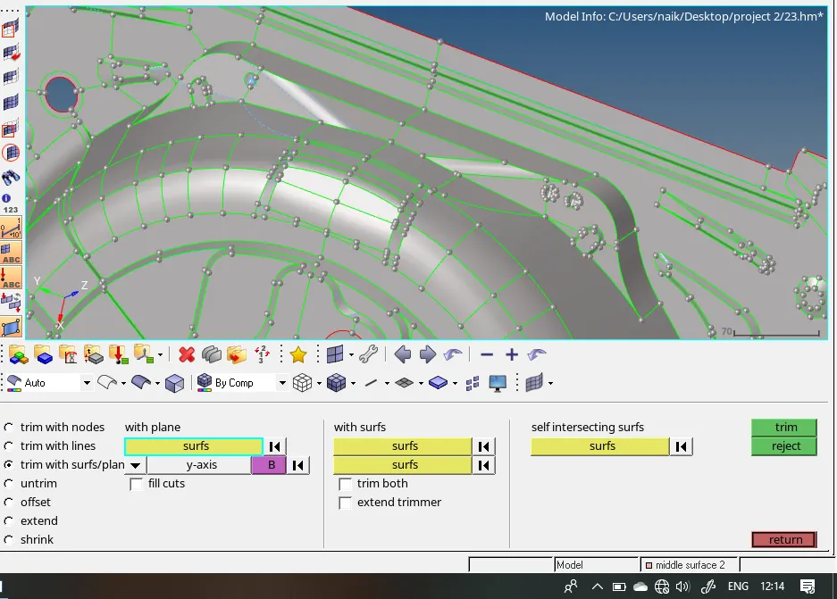
- To organize the surface in a different component.
As the surface needs to be assigned to a different component, we have to create a new component.
- Right-click – create – component.
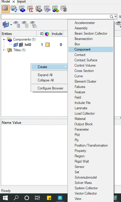
For moving the surface to new component follow the following procedure.
4) To generate the middle surface of the component
As the component has a uniform thickness of 0.75 thickness, we have to generate manual mid surface instead of the automatic generated surface. As the thickness in 2.75, to generate middle surface offsetting one of the surfaces to 0.375 that is half of the thickness. This process is the same for all varying thickness.
To offset the surface we have to check the thickness and then offsetting the surface to its half thickness.
- Check the thickness of the surface
Geometry - Temp nodes - create
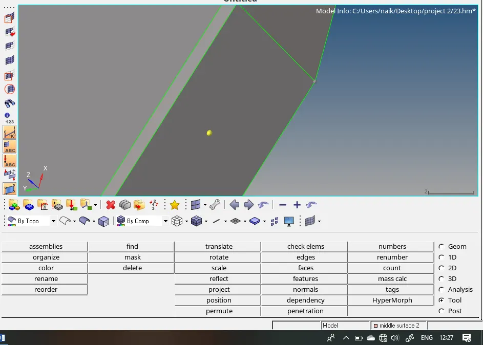
- Tools – Project – to surface – node – Duplicate
- F4 – Distance – Two nodes
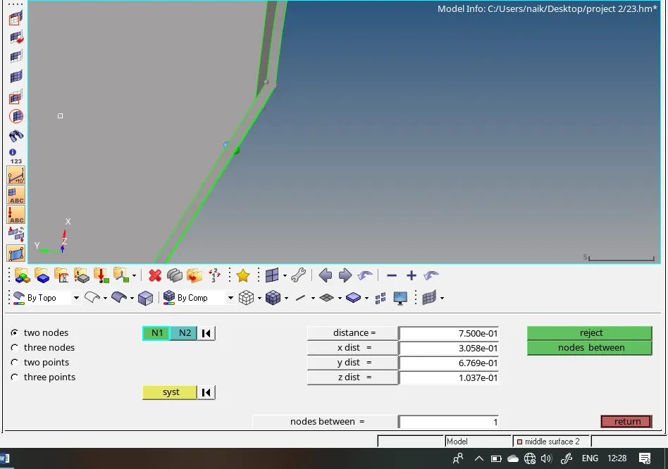
Generate Middle surface by offsetting the surface:
Geometry – Surface Edit – Offset – distance 0.375 – Duplicate – Offset
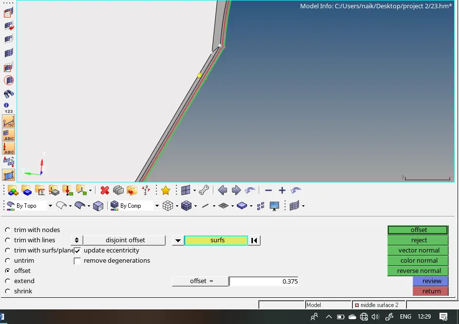
Manually create a middle surface for the complete geometry
As the given geometry is complex in shape it is difficult to generate the good quality mesh. In some region like pinholes, it is not possible to generate good quality middle surface using an offset option as the size of pinhole is less than the minimum length. To reduce the failing element we can defeature the edges and then generate the mesh.
i) Removing unwanted pin hole fittings.
For checking whether the geometry
Distance – two points – distance
If the distance is exceeding the minimum length then defeaturing the holes.
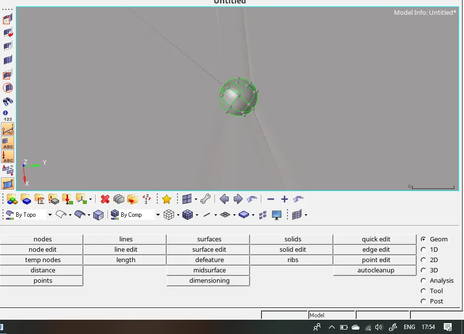
To defeature, surface delete the surface and then recreating surface using rule or spline option
2) To clean up the geometry and create a mesh.
Before cleaning the surface, we have to specify the editing parameters and at the same time, the “edit criteria”. While the editing parameter deals with geometry clean-up, the “edit criteria” deals with the element quality. Another important factor is that the element criteria are pre-determined within the problem statement.
Quality parameters are as follows.
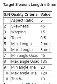
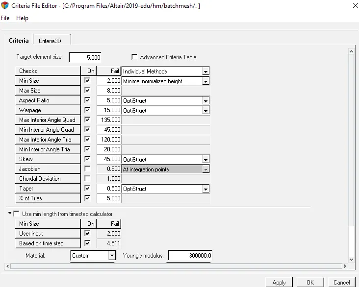
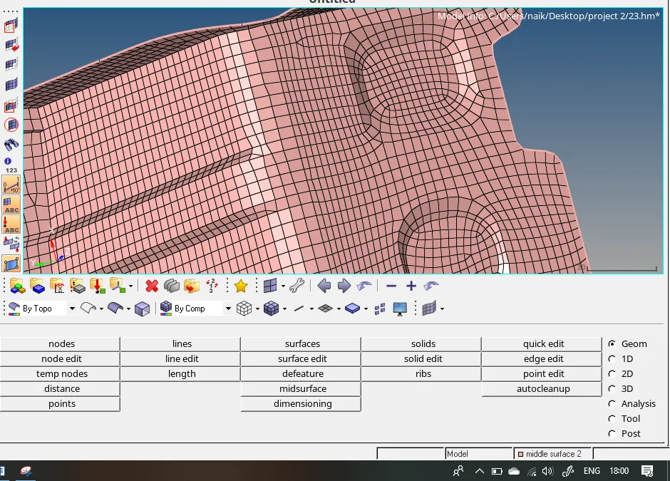
As the given geometry is of complex shape, we have to generate the so-called “quad dominating mesh” since we are going to use a mixed type mesh character and at the same time, keep the element size as 5. Also, to capture the whole surface properly, we have to manually generate mesh over the same region. To generate a clean mesh flow, we have to smoothen the mesh. Next step is to eliminate the “TRIA” since we have to combine the opposite direction of the so-called “TRIA” by dragging it on top of each other.
Some of the elements in this case also fail in quality since in such conditions, we can use the element optimization tool or the element clean-up tool.
There are some ground rules to be taken into consideration:
1) Optimizing the use of “TRIA”.
2) Eliminating the rotational Quads.
3) Placing the TRIA in the middle of geometry i.e. to avoid the use of TRIA on the edges.
4) Do not place TRIA in the fillet region.
3) To check the Quality Parameter of elements.
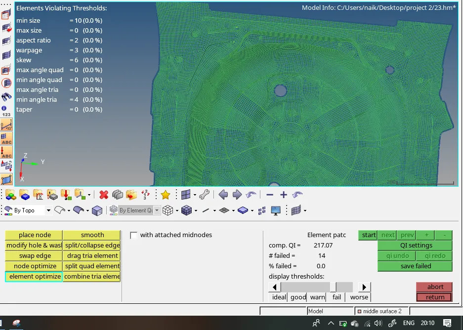
We cannot defeature some edges if we try to eliminate the element the geometry will disturb. So we have to keep some of the failing elements.
i) Tools – check Elements – parameters
Manual eliminating of the poor quality elements.
ii) To check the normal direction of the surface.
The direction of normal should be in a similar direction. Only then will the element will react similarly to the loading conditions.
Tools – Normal –Displayed
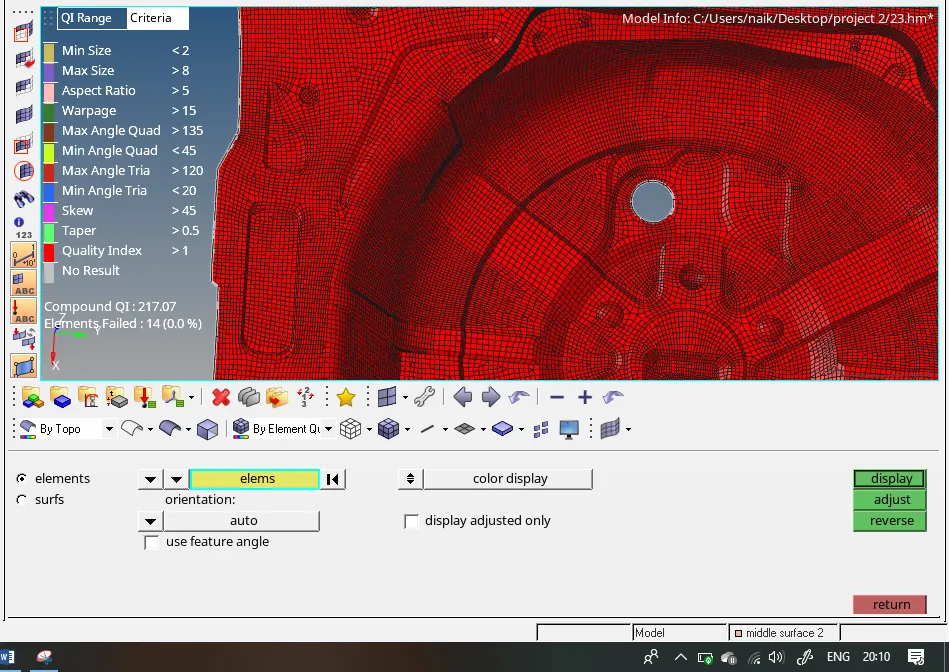
Make sure the elements are displaying a similar colour. If not, then manually reverse the direction of the normal direction.
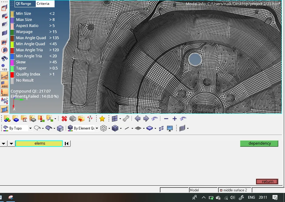
iii) To check the dependency of element and penetration.
The element should not depend on more than 1 element. If it is more than 1, then the element will fail while solving the loading condition. The purpose of the penetration tool is to check whether elements are not overlapping with other elements or intersecting with each other.
iv) To check the free edges:
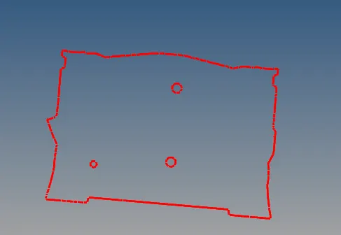
As the meshing took place manually it is important to check the meshing connectivity of different connecting surface if the mesh is not connected then manually connecting the mesh using replace option. Even though if the mesh is not connected then while performing analysis the result will not be uniform in that region.
Tools – Edges – displayed – find
- v) To associate the thickness to model
Right-click – Create – Properties - thickness – 0.75
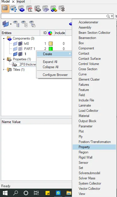
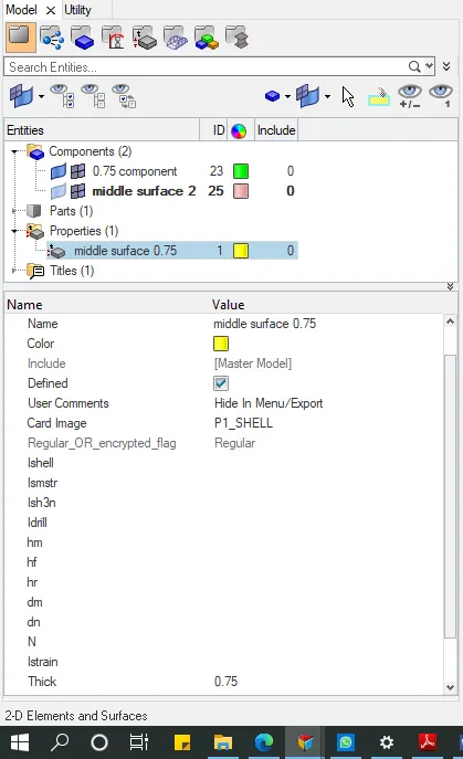
If the thickness is different on various section of surface the create multiple properties of multiple thicknesses.
Components – properties – Properties
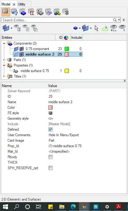
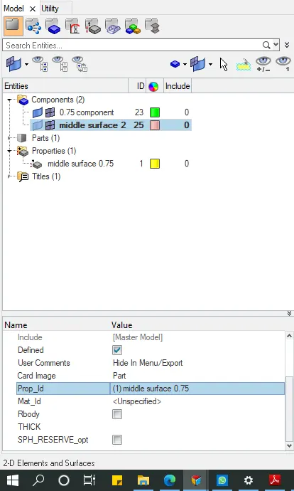
This process applies to all the components.
Conclusion:
With this exercise, we learned new tools which would improve the accuracy, quality and at the same time, reduce the meshing time. We also learned new features such as Automesh, Quality Index, removing rotational Quad, eliminating “TRIA”, smoothing the element flow, changing the quality parameter, Auto clean-up and its parameters, importance of washer and the projection of nodes.
Result:
From this project, we got to know the tools to generate a mesh and to clean-up the quality of elements. We also learned various techniques to generate mesh effectively.
Final component: