Week 9 Challenge
Soln 1)
Given data:-
Roof Slope 1:10
Bay Spacing = 5 m
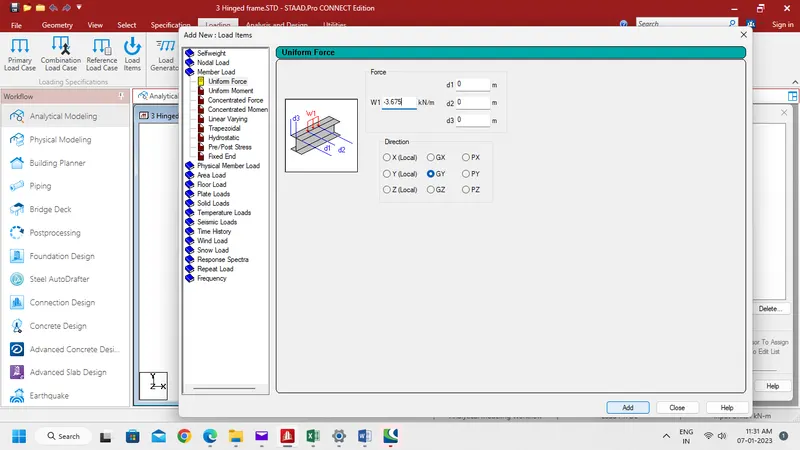
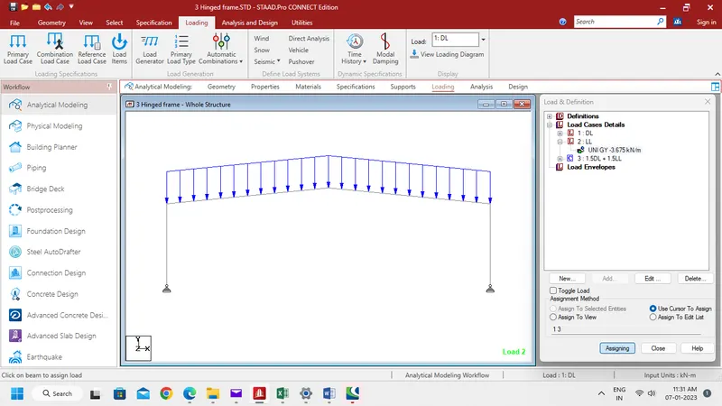
Live Load = 75 kg/m2 = 0.735 kN/m2 = 0.735 x 5 = 3.675 kN/m
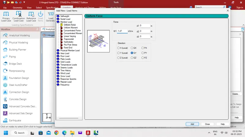
Dead Load = 5 kg/m2 + 25 kg/m2 = 30 kg/m2 = 0.294 kN/m2 = 0.294 x 5 = 1.47 kN/m
Aim:-
To Design a 3 hinged pitched roof frame of a steel building and draw bending moment, shear force and axial force diagrams of the frame.
Procedure:-
Step 1:-
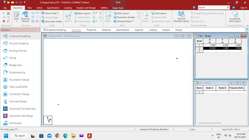
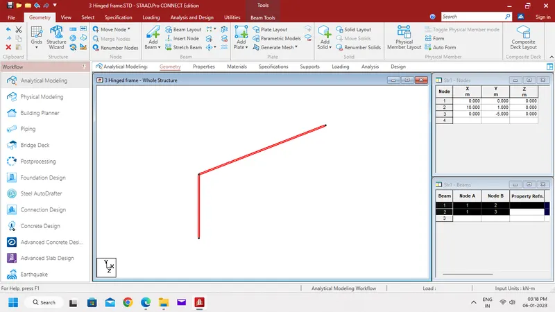
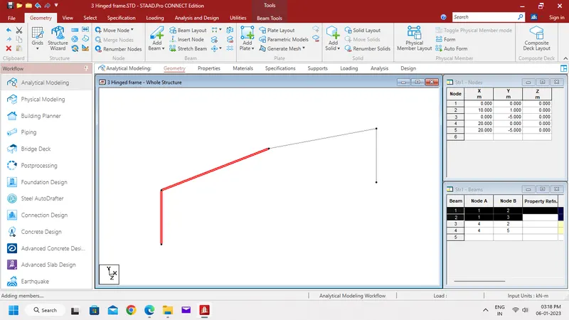
- Open the STAAD Pro Software and create a new model as shown below.
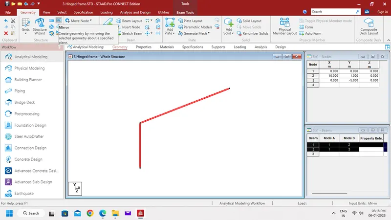
- Using Nodes and Beams option draw the Frame as shown below.
Step 2:-
- Define Section properties in the Properties Tab.
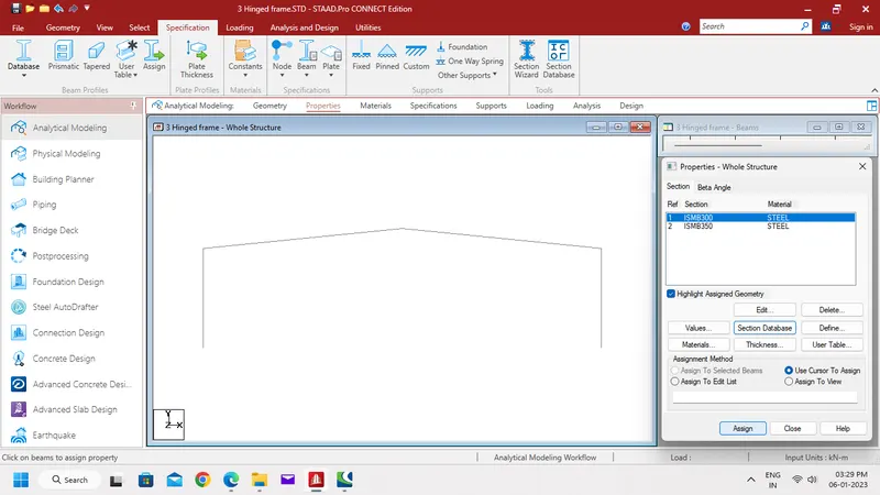
- Then assign Sections to the members.
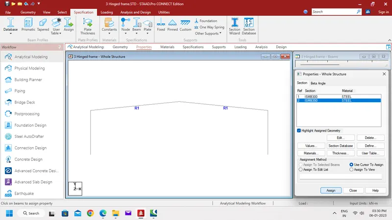
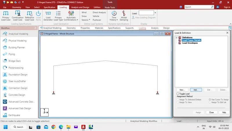
- Now create and assign the Pinned support
Step 3:-
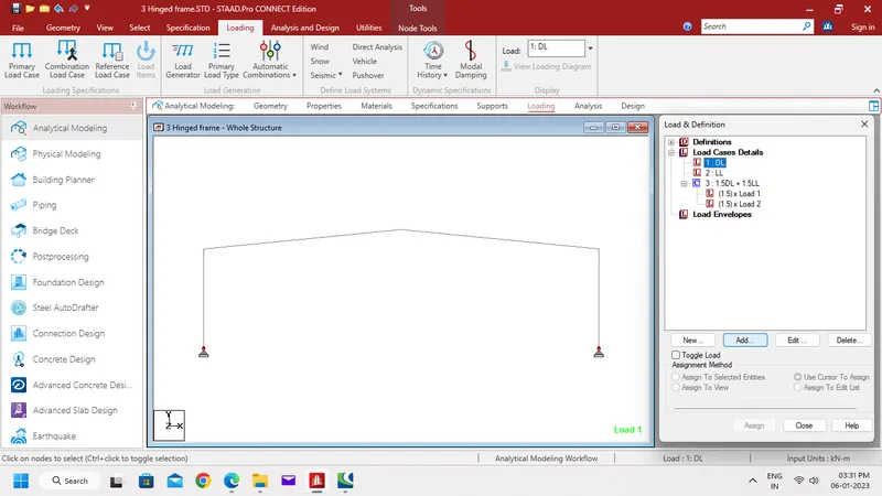
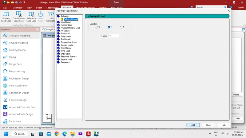
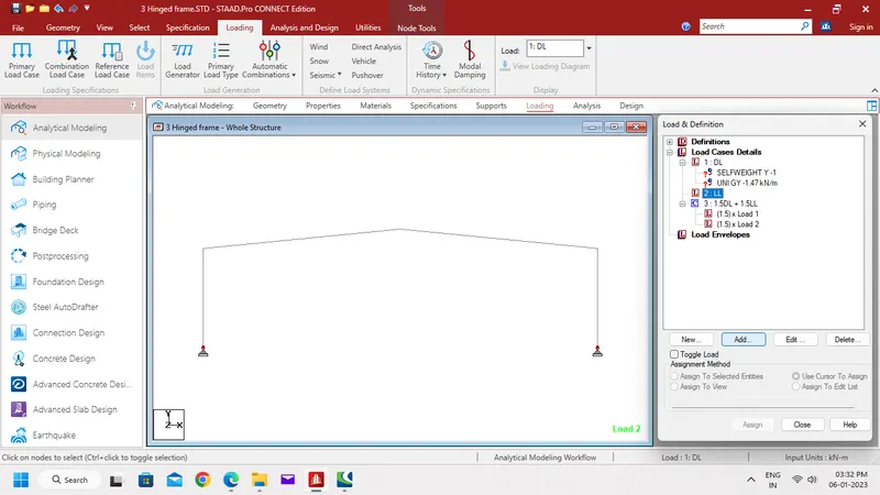
- Add Dead Load, Live Load and Load Combination to the members.
Step 4:-
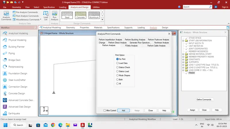
- Now go to Analysis Tab and Define Perform Analysis.
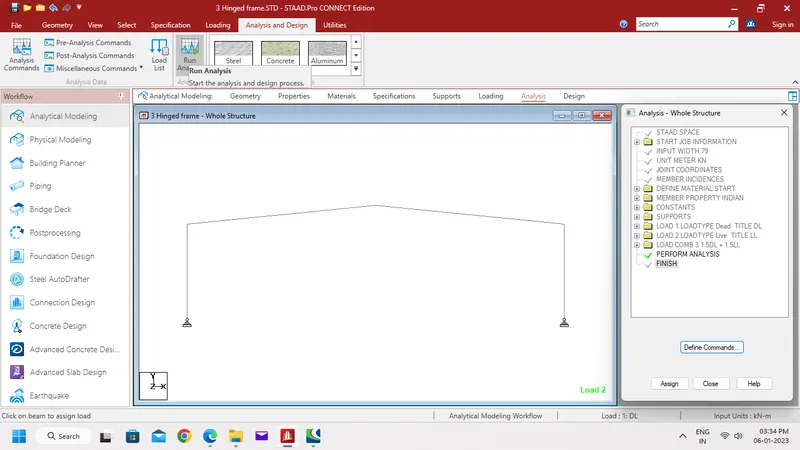
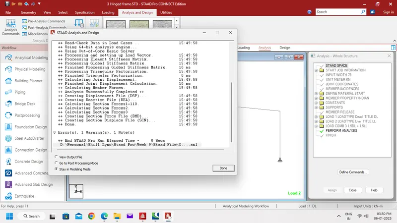
- Output shows 0 Error and 1 Warning.
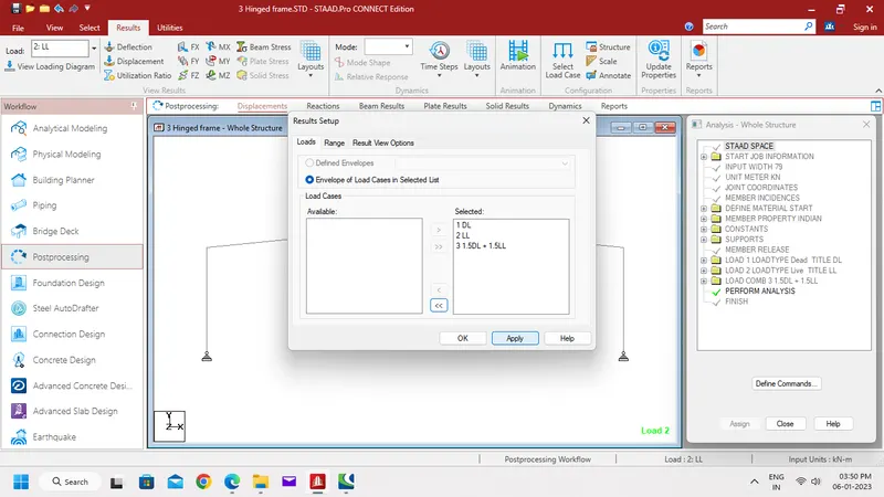
Result:-
- The given frame was analysed and the bending moment, shear force and axial force diagram created.
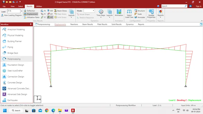
Bending Moment diagram
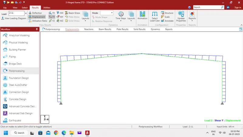
Shear Force diagram
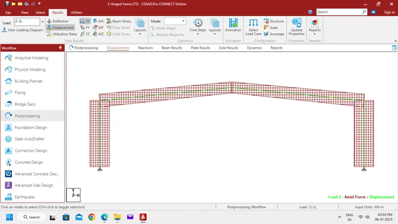
Soln 2) Axial Force diagram
Aim:-
To draw Bending Moment diagram for the frame given using STAAD Pro.
Procedure:-
Step 1:-
- Draw the frame using Nodes and Beams option.
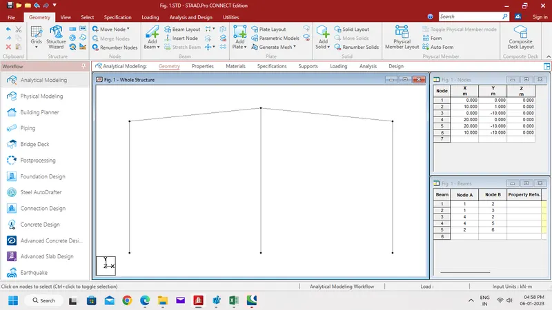
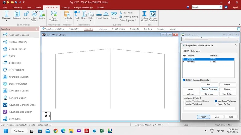
Step 2:-
- Define and Assign the Section properties to the member.
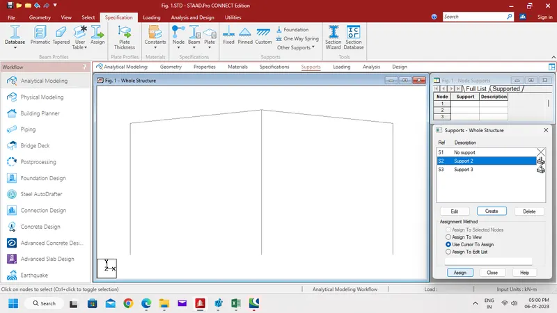
Step 3:-
- Then create and assign the support to the frames.
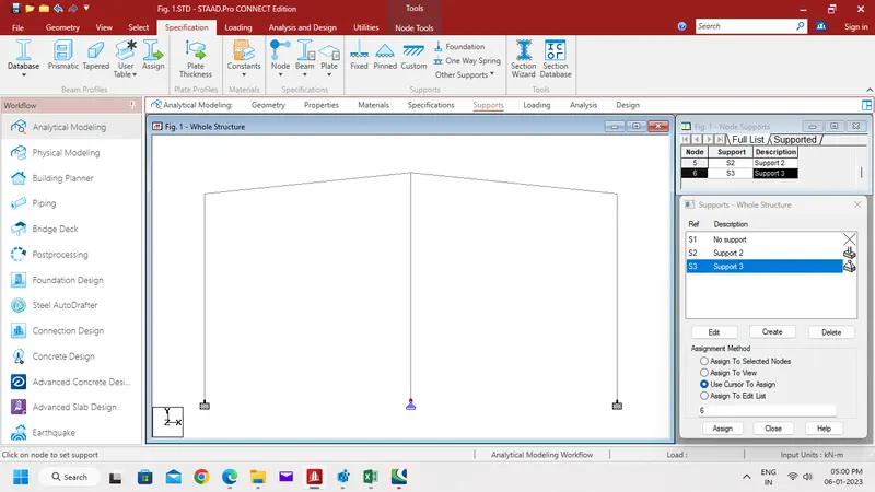
Step 4:-
- Add Load cases given and assign to the frame members.
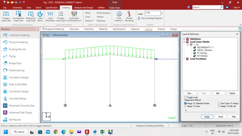
Step 5:-
- Go to Analysis Tab, define Perform Analysis.
- Then Click Run Analysis.
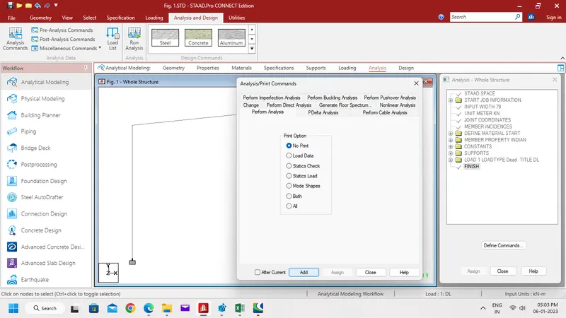
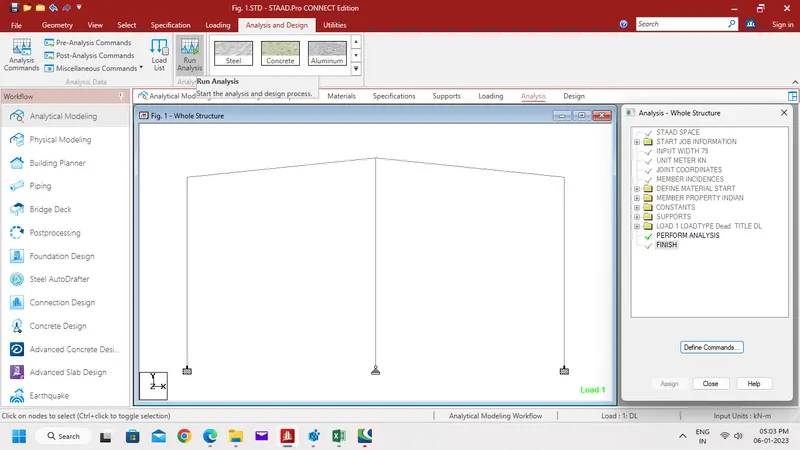
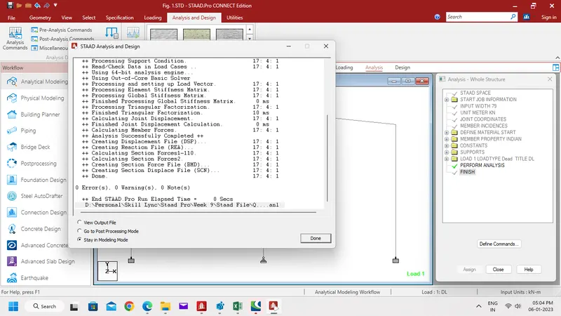
- Output shows 0 Errors and 0 Warnings.
Result:-
- Bending moment diagram was drawn for given frame successfully.
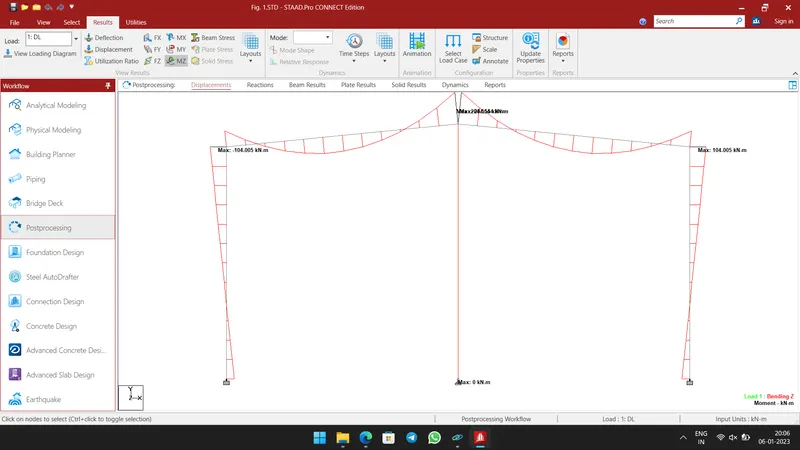
Figure 2)
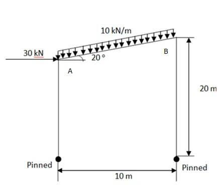
Aim:-
To draw Bending Moment diagram for the frame given using STAAD Pro.
Procedure:-
Step 1:-
- Draw the frame using Nodes and Beams option.
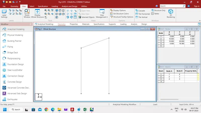
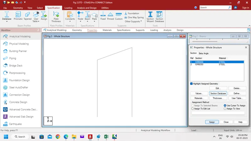
Step 2:-
- Define and Assign the Section properties to the member.
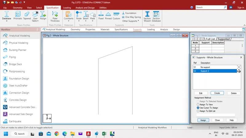
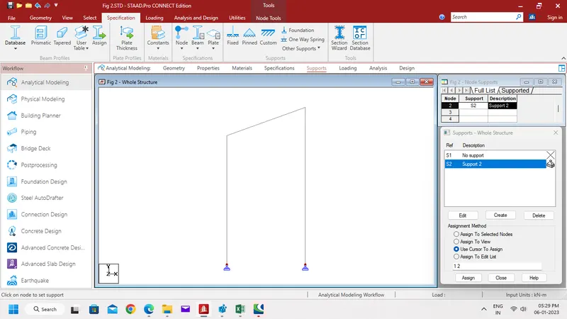
Step 3:-
- Then create and assign the support to the frames.
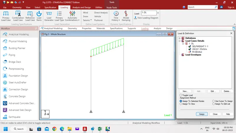
Step 4:-
- Add Load cases given and assign to the frame members.
Step 5:-
- Go to Analysis Tab, define Perform Analysis.
- Then Click Run Analysis.
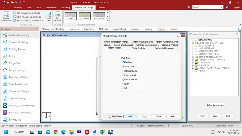
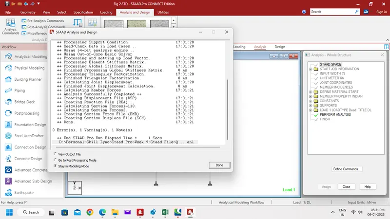
- Output shows 0 Errors and 1 Warnings.
Result:-
- Bending moment diagram was drawn for given frame successfully.
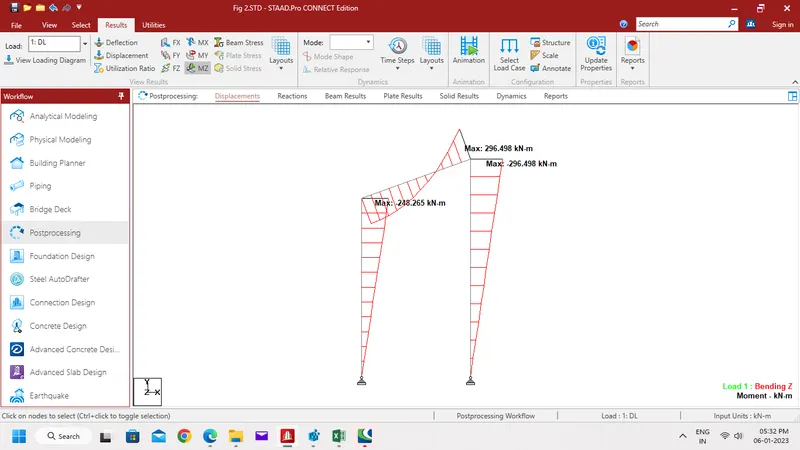
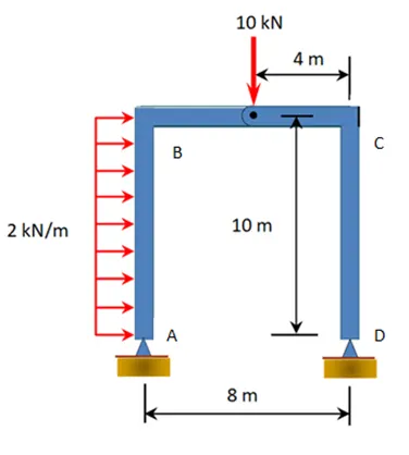
Figure 3)
Aim:-
To draw Bending Moment diagram for the frame given using STAAD Pro.
Procedure:-
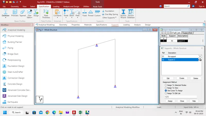
Step 1:-
- Draw the frame using Nodes and Beams option.
- Define and Assign the Section properties to the member.
- Then create and assign the support to the frames.
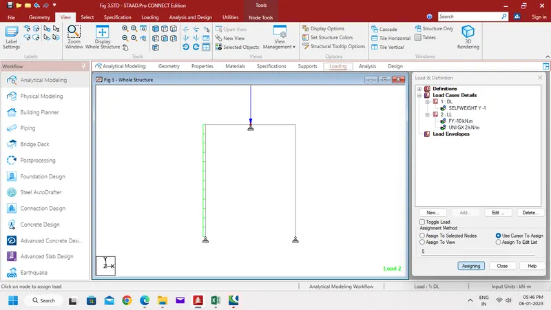
Step 2:-
- Add Load cases given and assign to the frame members.
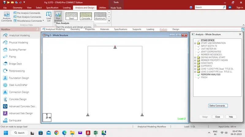
Step 3:-
- Go to Analysis Tab, define Perform Analysis.
- Then Click Run Analysis.
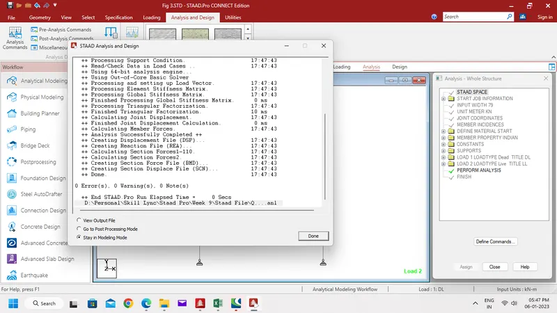
- Output shows 0 Errors and 0 Warnings.
Result:-
- Bending moment diagram was drawn for given frame successfully.

Answer 3
Figure 1:
The lateral deflection at point A = 0.090 mm
Vertical deflection at mid section of beam between B & C = 27.846 mm
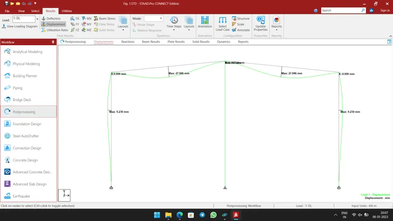
Figure 2:
The lateral deflection at point A = 1003 mm
Vertical deflection at mid section of beam between A & B = 1005 mm
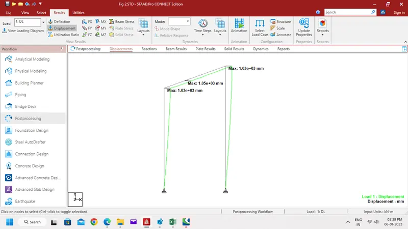
Figure 3:
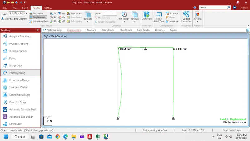
The lateral deflection at point A = 0.051 mm
The lateral deflection at point B = 0.000 mm