Week 9 Challenge
AIM AND INTRODUCTION:
- To calculate the wave load on the bridge superstructure for the given dimensions, and to apply the calculated wave load on the bridge structure using staad pro and to perform structural analysis.
- wave load is caused due to the disturbance of the water surface.
- According to the intensity of the wind, the wave generates a force on the bridge substructure like piers and abutments.
- These wave loads will cause damages to the structure and have a tendency to uplift the superstructure.
- wave loads have two components
- The crust - The highest point of the wave.
2. The trough- The lowest point of the wave.
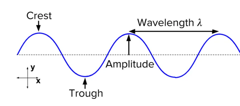
Fig. 1
- The distance between crust and trough is Height.
PROCEDURE:
- First we need to calculate the wave forces from the given data.
- Maximum crest elevation = 3m
span of the bridge = 12m
width of deck slab = 9m
Thickness of deck slab = 2m
constant(r) = 5, Cva= 3, Cr= 0.4
storm elevation = 8.5m,
Maximum crest, (N)max = 3
No. of I girder supporting deck = 3
- Wave load, Fv* = Y(△Zv)Av
where, Av= Area the bridge contributing to vertical uplift,
△Zv= difference between elevation of crest of maximum wave and elevation of underside of bridge deck.
Y= unit weight of water.
- Wave load, Fh* = Y(△Zh)Ah
where, Ah= Area of projection of bridge deck onto vertical plane.
△Zh= diff. between elevation of crest of maximum wave and elevation of the centroid of Ah.
- △Zh = 3-(1.7/2) = 2.15,
- △Zv = 3-2 = 1
- Vertical load, Fv* = Y(△Zv)Av
= 10 * 2.15 * (9*(1.7/2))
= 164.475 KN.
- Horizontal load, Fh = Y(△Zh)Ah
= 10 * 1* (12*3)
= 360 KN.
- Max. Vertical load, (Fv)max = Cva * Fv
= 3 * 164.475
= 493.425 KN.
- Max horizantal load, (Fh)max = (1+Cr(N-1)) * Cva * Fh
= (1+0.4(3-1)) * 3 * 360
= 1944 KN.
- We apply the max vertical load and max horizontal load as calculated above, on the bridge structure, and perform analysis in staad pro.
- Creating bridge structure in staad pro.
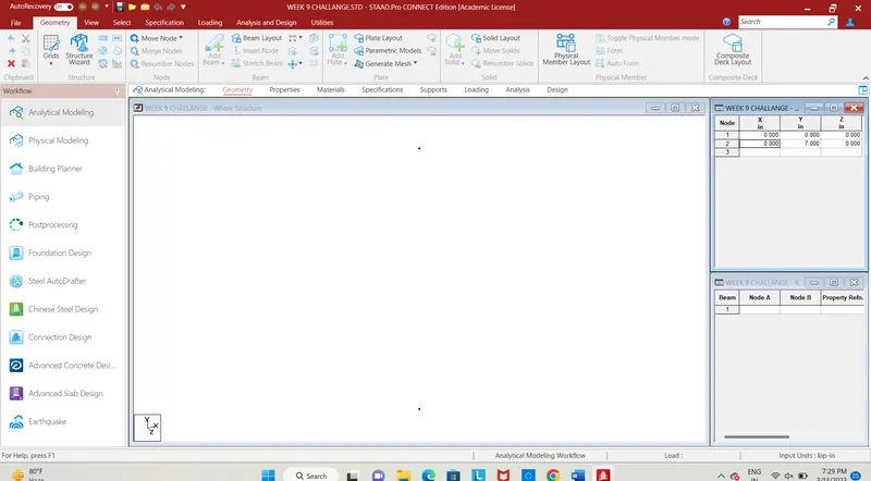
Fig. 2
- First, enter the coordinates for the pier, the coordinates are (0,0,0) (0,7,0) and connect the nodes by using add beam command in the Geometry tab.
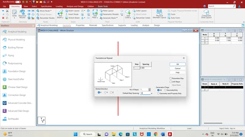
Fig. 3
- The next step is to copy the pier in the x-direction at a distance of 12m, with one step, use the translational command in the geometry section to copy the pier, thus it gives the span of the bridge.
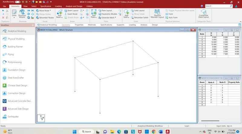
Fig. 4
- The next step is to copy both the piers in the z-direction at a spacing of 9m, with one step repeat using translational repeat command.
- The 9m is the width of the deck slab.
- Connect the piers by using add beam command, the beam added is longitudinal beam and cross beam hence the bridge structure with main and cross girder is designed.
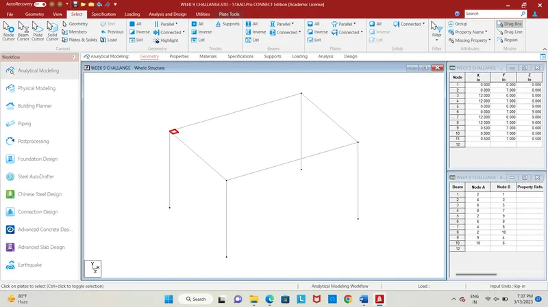
Fig. 5
- Then we need to add plates, for that first copy the corner node in the x-direction at a spacing of 0.5m using translational repeat command.
- Next copy the two nodes in the z-direction, at 0.5m spacing, hence the 4 nodes were added, connect the nodes by using add plate command in the Geometry section.
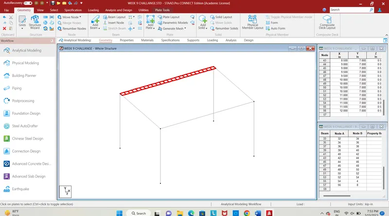
Fig. 6
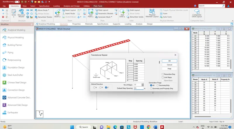
Fig. 7
- We need to form the deck slab, for that add plates to the entire width and length of the beam, using translational repeat command copy the plates in X-direction and Z-direction.
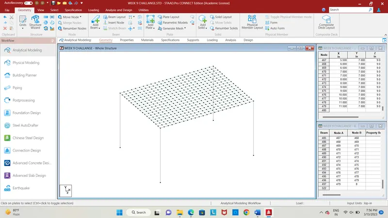
Fig. 8
- The deck slab for the entire slab has been added as shown in the figure, next we need to specify the properties for beams, piers and plates.
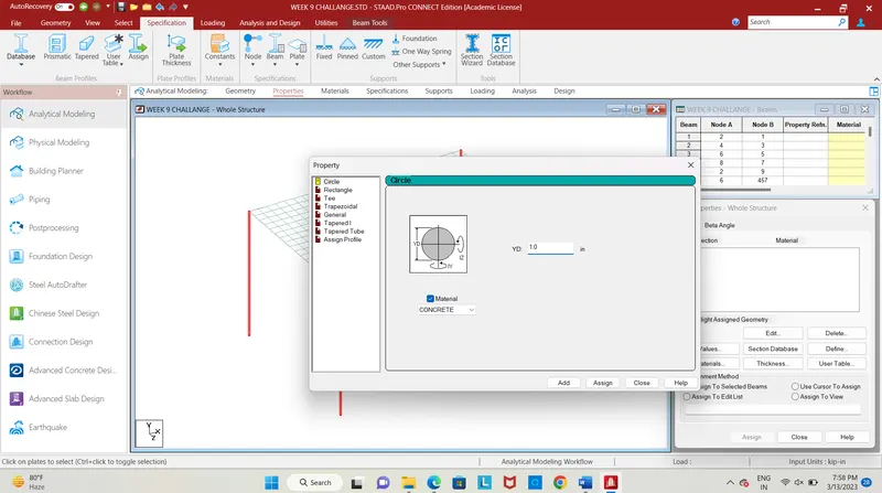
Fig. 9
- In the specification tab for piers add a circular section of dia 1.0m, select the 4 piers and click assign to selected beam, the property will be assigned to pier.
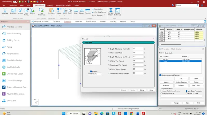
Fig. 10
- Next, add a taper section for the I girder, enter the dimensions as given, The I girder will be a longitudinal girder which is the main girder for the bridge.
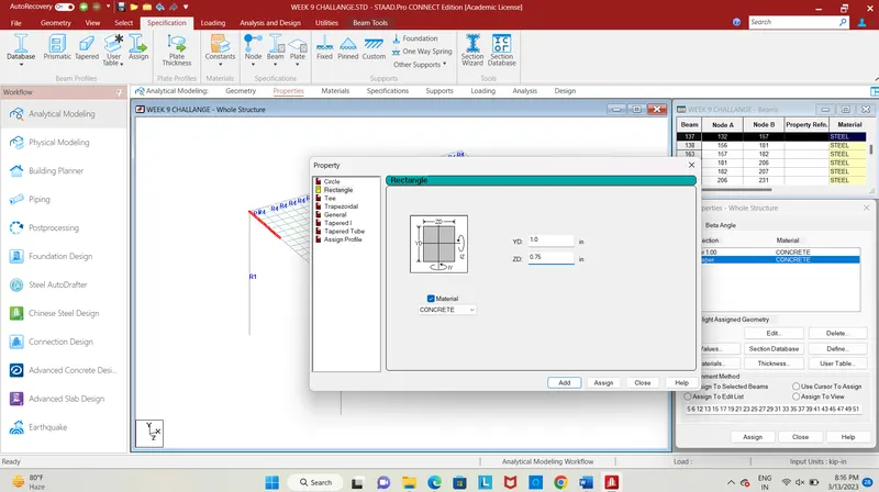
Fig. 11
- For cross beam add a rectangular section of (1 * 0.75) m, select the beams and click assign to selected beams.
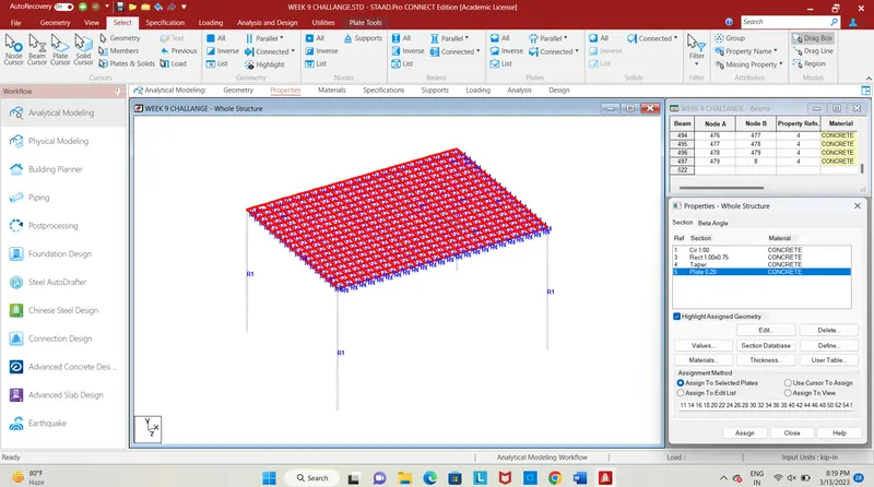
Fig. 12
- Add a plate thickness of 200mm and assign it to the deck slab.
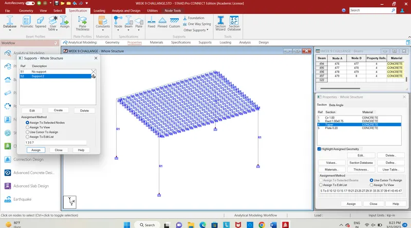
Fig. 13
- Provide fixed support to the structure.
- Now, we apply loading to the structure.
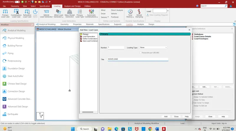
Fig. 14
- The next step is to give loading to the structure add load case details, give title as wave load, we can apply the calculated load as nodal loads.
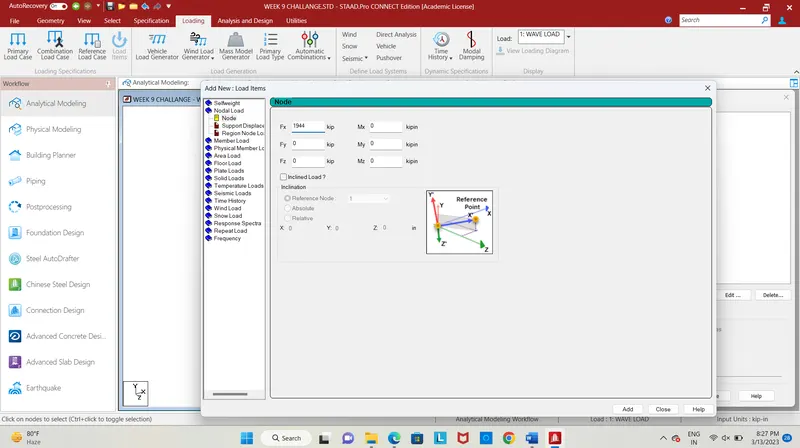
Fig. 15
- Click on wave load, and click add select nodal loads, add the calculated load values for x and y-direction which is the horizontal and vertical loads respectively.
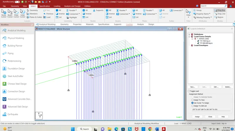
Fig. 16
- Select the nodes in the deck slab in the middle and apply the load, select the load and click assign to selected nodes thus the load will be applied, next step is to analyze the structure in the post-processing mode.
RESULT:
- Next we need to run the analysis for the designed structure, click on the run analysis command after analysis enters into post-processing mode .
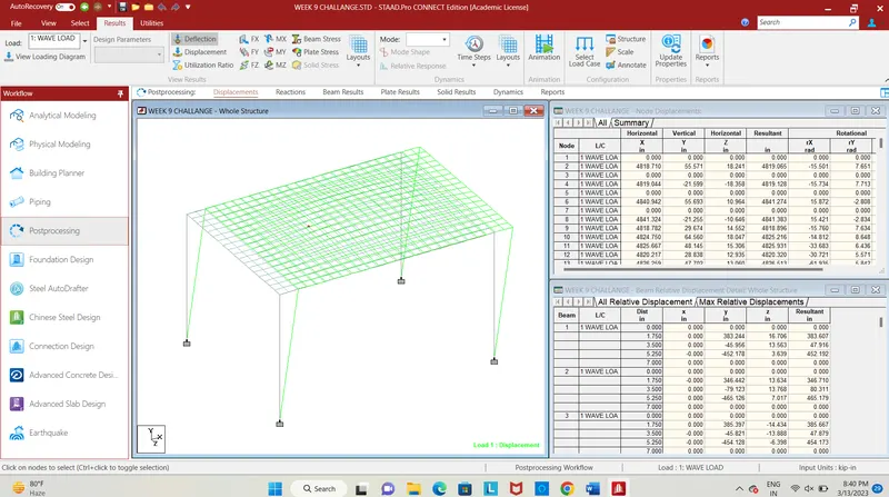
Fig. 17
- The deflection of structure is for the applied wave load is shown above, the pier and slab get deflected.
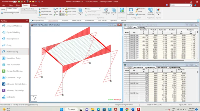
Fig. 18
- The bending in structure along Mz due to wave load is shown.
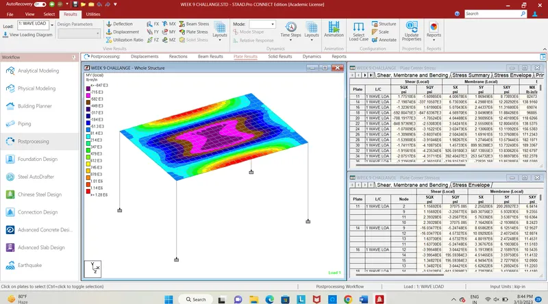
Fig. 19
- The plate stress for the applied load is shown in the contour diagram, in the post-processing section select the plate stress, give stress type as My and click ok.
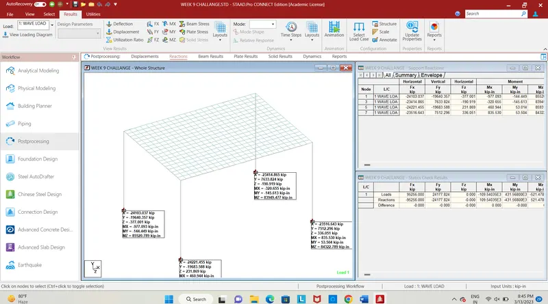
Fig. 20
- The reaction values are shown above for the pier, thus load has been calculated, the bridge was designed for given dimension and load has applied in the bridge after that structure has been analyzed for the applied load.