Week 9 Challenge
Week- 9
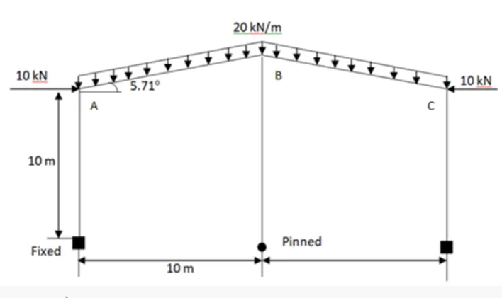
Q.1 Design of Dual Slope (Pitched) roof frame.
Assume no wind load acting on the walls and roof. Analyse the frame structure and draw bending moment, shear force and axial force diagrams of the frame. The slope of the roof is 1 in 10 and the roof is accessible for maintenance purpose (assume 75 kg/m2) only. Dead load on the roof are given below. Assume bay spacing as 5 m and frame width is 20 m. (Design code as per AISC:ASD. No seismic load consideration required)
- Weight of roofing sheet = 5kg/m2
- Weight of purlins + tertiary members = 25 kg/m2
Procedure: -
- Open Staad pro and create nodes after that by click on add beams and connect the node to nodes beams
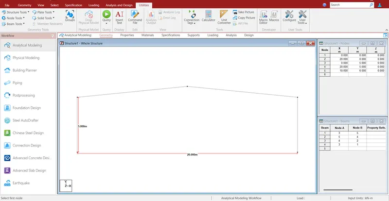
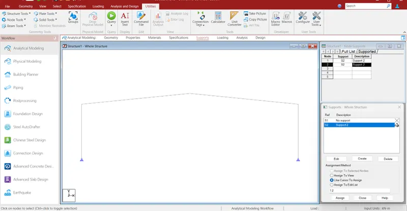
- Support - Go to support tab and click create – Select pinned – click add.
- Assigning supports – Select nodes by using node cursor – Assign to selected member.
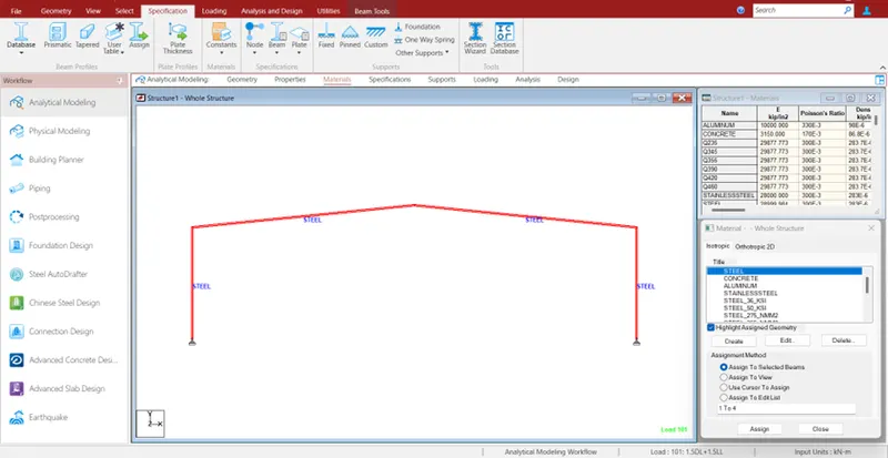
- Properties :- GO to properties – Select Steel – Assign to view
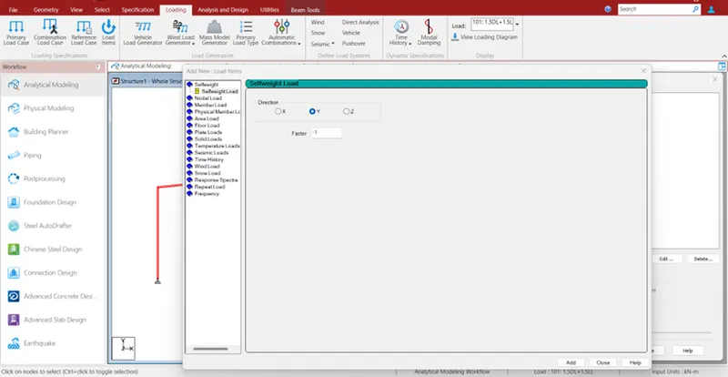
- Loading- Add Dead Load, Live Load and Load Combination for the member
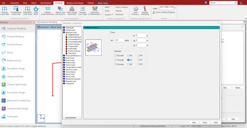
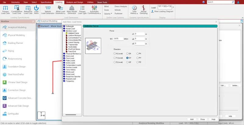
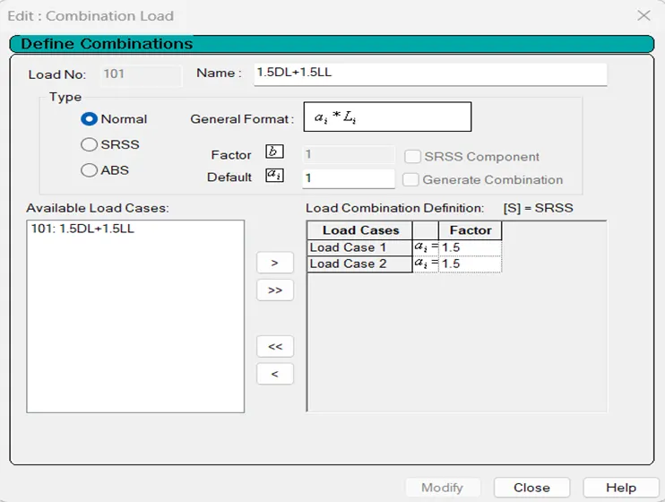
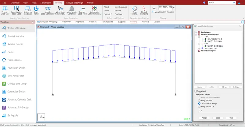
- After applying of loadings , Go for Run Analysis and check for Errors and warnings and after that proceed for post processing tool
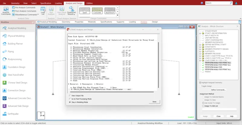
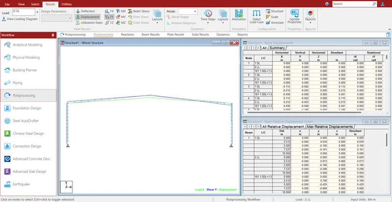
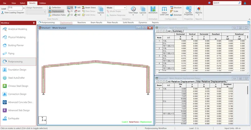
Results:- Given frame analyzed and Bending Moment, Shear Force and Axial Force drawn below.
- Bending Moment
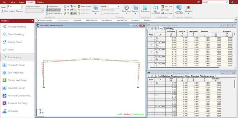
- Shear Force Diagram
- Axial Force Diagram
- Draw Bending Moment diagram for following Frame using STAAD.Pro
Given Data
Figure 1)
Procedure :-
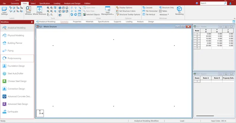
- Geometry- Creating of nodes
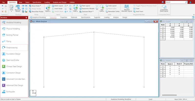
- Add Beams
- Properties:- Go to Section Database – Select Indian – Choose Member Size – Add
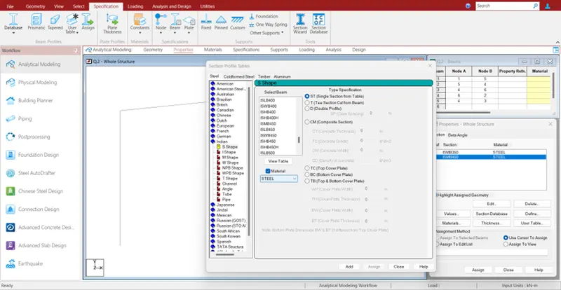
- Assign Properties:- Select the member and click assign to selected member
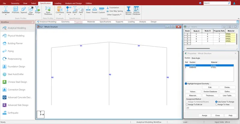
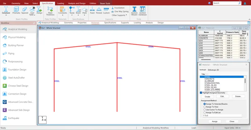
- Materials- Steel
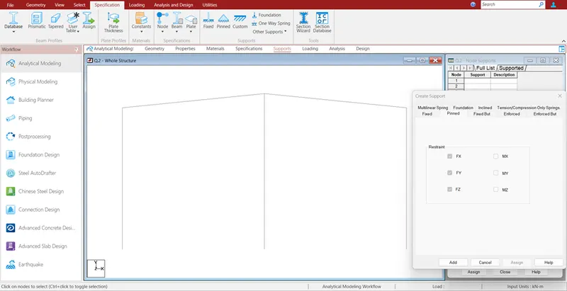
- Supports- Click on Add – Choose Fixed and Pinned support and click add.
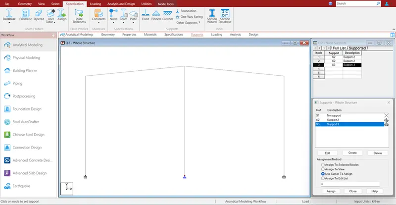
- Assign Supports- Select the Nodes and assign to selected nodes.
- Loading:- Go to Load Case – Add – Type Dead Load – Add loading data and assign the loads to the member.
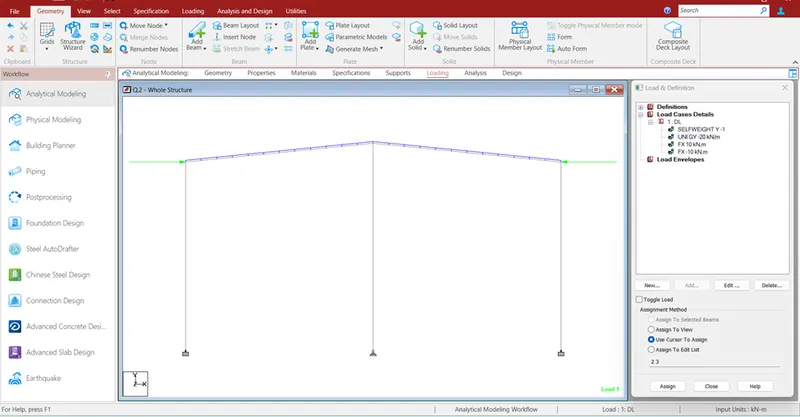
- Run Analysis- Check the errors.
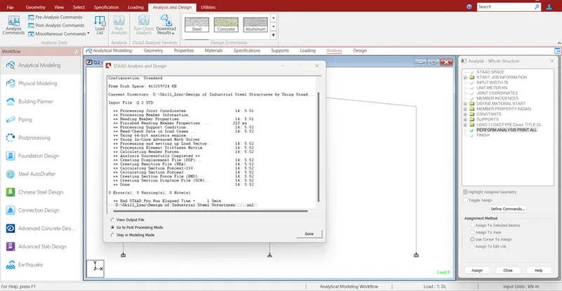
- Bending Moment Diagram
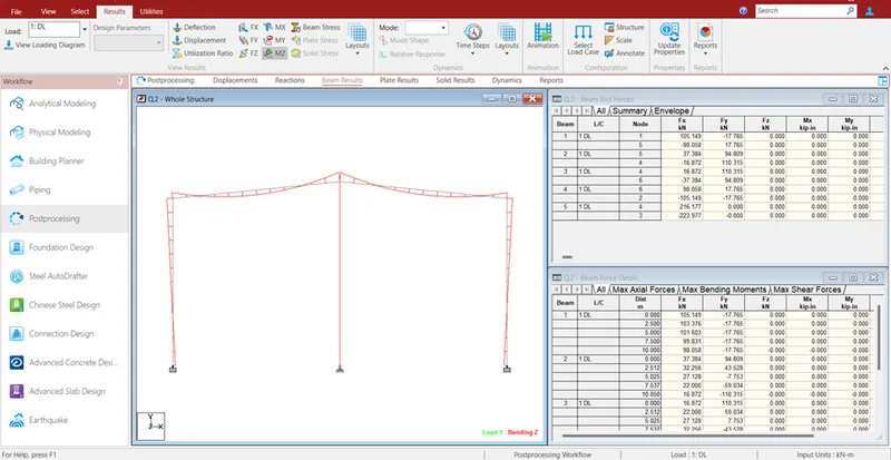
Result:- Bending moment diagram drawn with given fig.1
Fig- 2
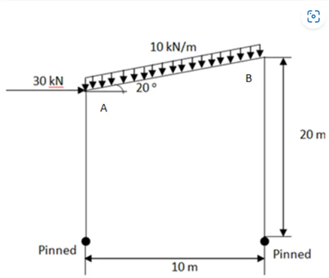
- Follow same steps as shown in fig-1
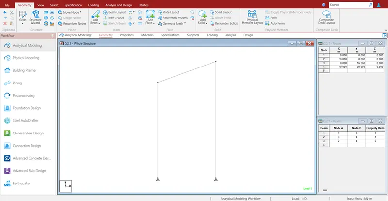
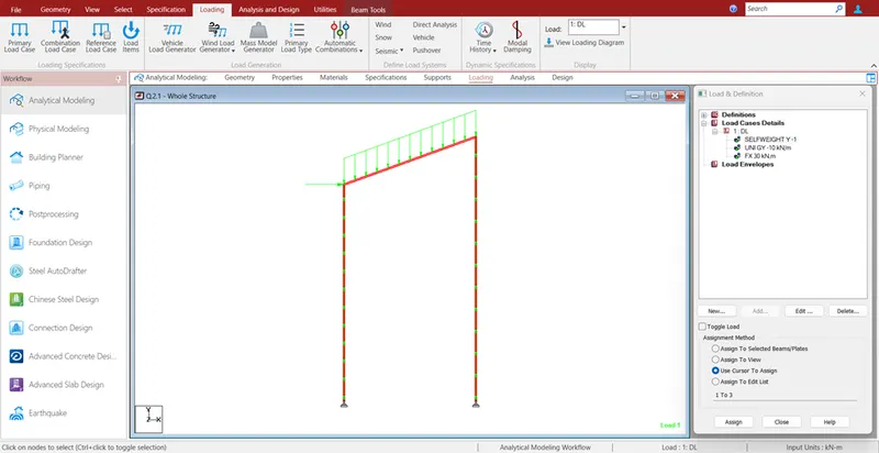
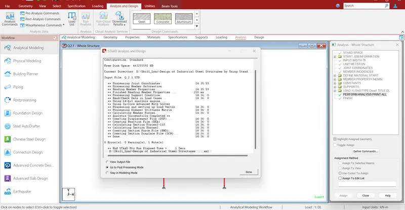
- Bending Moment Diagram
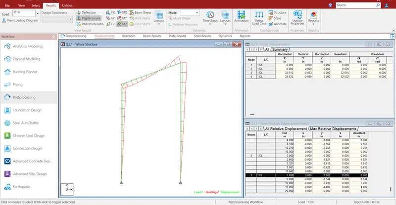
Results:- Bending Moment diagram drawn with given frames by using staad pro.
Fig.3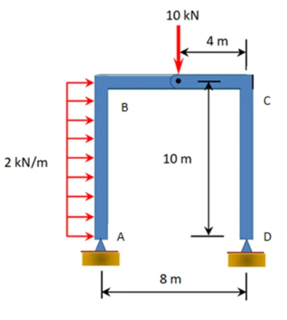
Procedure:-
- Please follow the same steps.
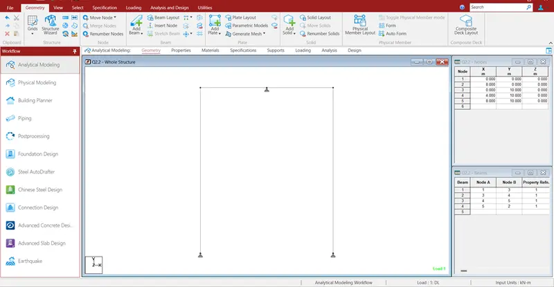
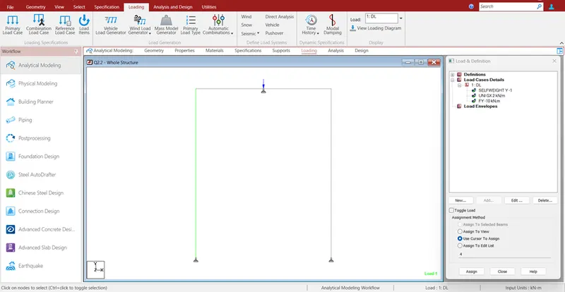
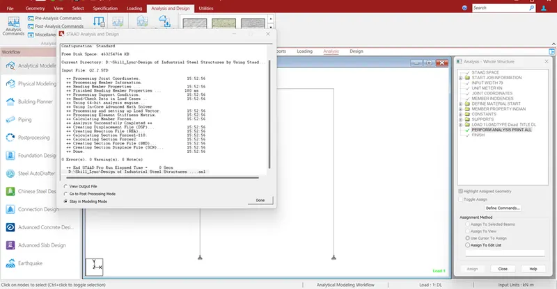
- Bending Moment Diagram
Results:- Bending Moment diagram drawn with given frames by using staad pro.
- Deflection of a frame, present result from STAAD.Pro
- Determine the lateral deflection at point A & Vertical deflection at mid section of beam between B & C from Figure 1 in previous challenge.
- Determine the lateral deflection at point A & Vertical deflection at mid section of beam between A & B from Figure 2 in previous challenge.
- Determine the lateral deflection at point A & point B from Figure 3 in previous challenge.
Fig1.
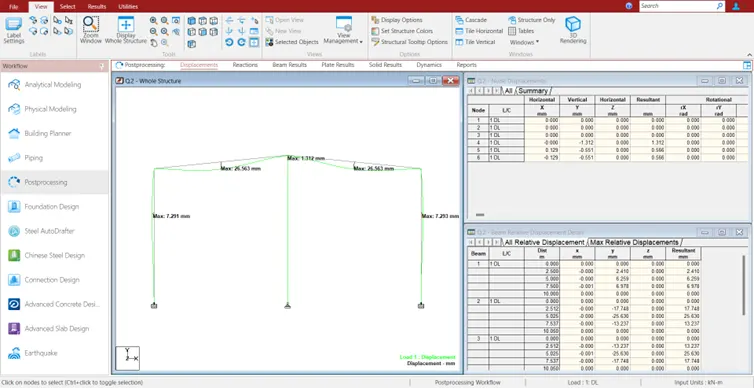
Fig.2
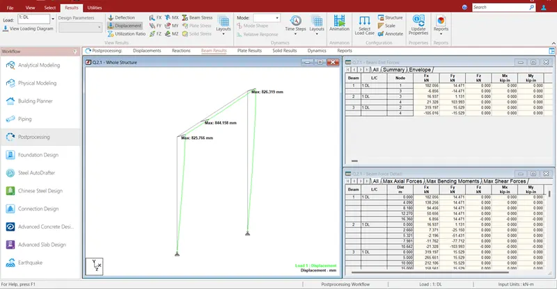
Fig- 3
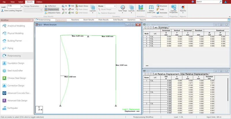
Result:- Lateral Deflection shown in above diagram.