Week 9 Challenge
Waves also distress bridge sub structure and superstructure. Outer forces typically disturbs water, causes forming of wave. Earthquake, Wind and other substance present in water unstable water surfaces. Waves have great power. Wave acts in two direction, causing two types of load, one is uplifting and other is dragging. So chances of complete damage of superstructure is predictable. Assessment of forces or loads generated by wave and further calculation of maximum bending moment and then design of bridge substructure and superstructure is must.
Here we have to solve problem, caused by wave loads to a bridge superstructure of 12m span, 9m wide rested on 3 No 1.7m high i girders. Deck slab is 2m thick and pier is 7m high.
Crest elevation for wave (n max) is 3m, so it is 3m higher than SWL. Storm elevation is 8.5m so it is 1.5m higher than Pier top and will cross through I girder. r and Cva constant is assumed 5 and 3 respectively. Cr is taken as 0.4
 Zh = n max - centroid of I Girder
= 3.00m - [3.7/2] = 1.15m
Zv = n max - Elevation ofbottom deck
= 3.00m - 0.80m = 2.20m
Number of girders supporting bridge deck N = 3
Verticle load Fv = r X Z v X Av
= 5 X 2.20m X [9 X (3.7/2)] = 183.15kN
Horizontal Load Fh = r X Zh X Ah
= 5 X 1.15 X [24 X 4.5] = 621.00kN
Max verticle load = Fv max = Cva X Fv = 3 X 183.15 = 549.45kN
Max horizontal load = Fh max= ( I + Cr (N-I)) Cva X Fh = (1+0.4[3-1]) X 3 X 621.00 = 3353.40kN
Modelling bridge
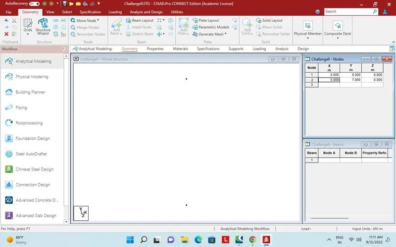
Nodes created at 7m for pier
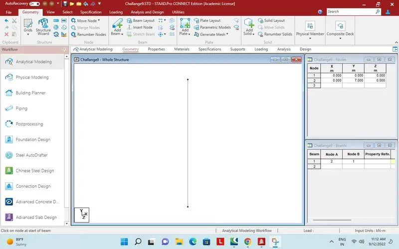
Nodes added by add beam
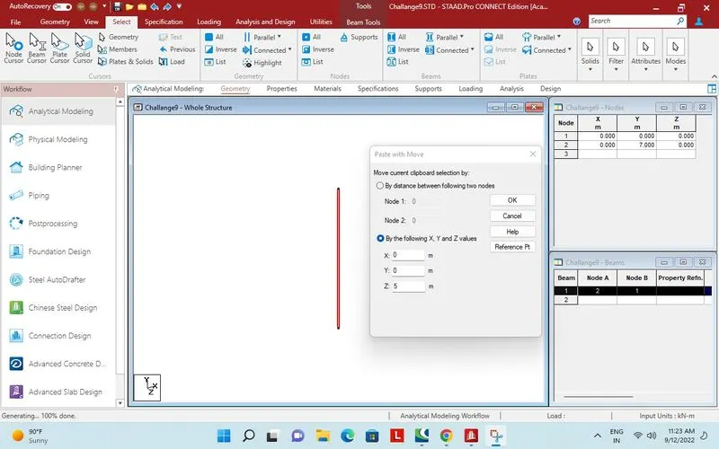
Beam copied to paste in Z direction.
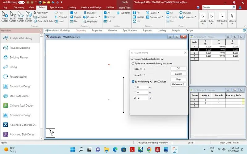
Node selected to paste in - Z direction at a distance of 2m.
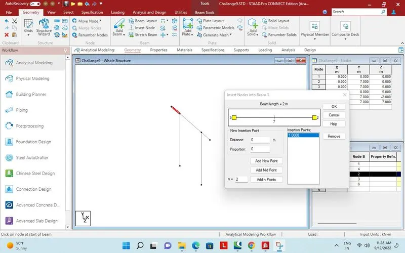
Beam extended in Z direction both side for cantilever portion.
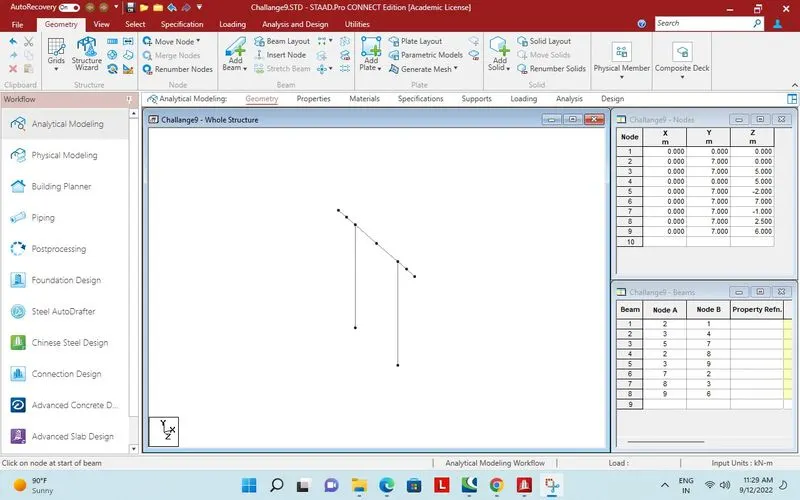
Point inserted in middle.
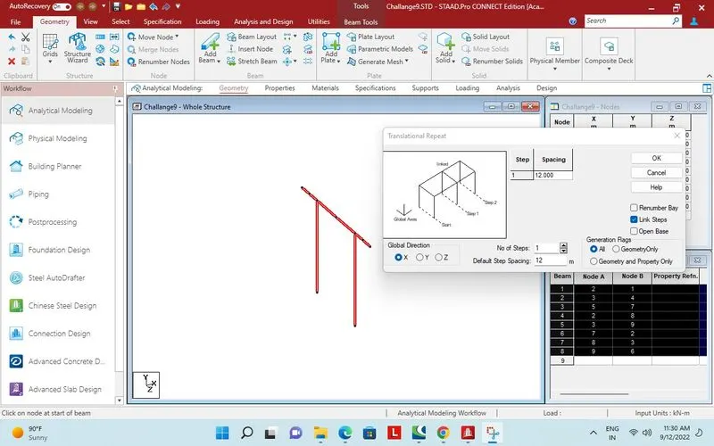
Full bay selected for traslational repeat in X direction 12m distance.
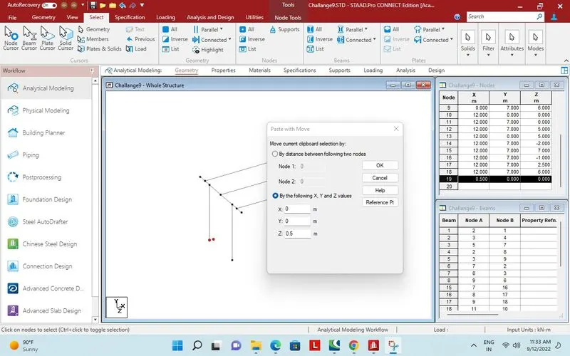
Node created in X direction distance 0.5m, and selected for translational repeat in Z direction 0.5m distance.
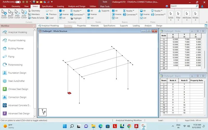
Plate created by joining four nodes.
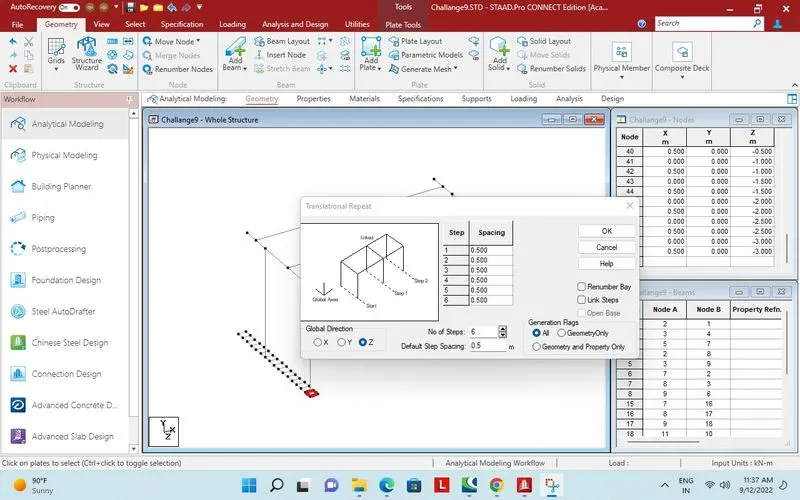
Translational repeat in Z direction 6 times and 0.5m distance.
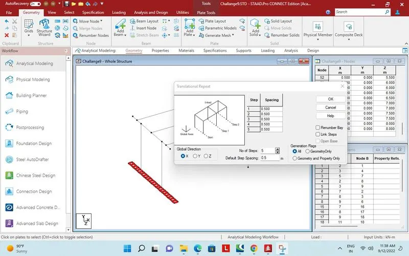
Plates in Z direction for foundation created.
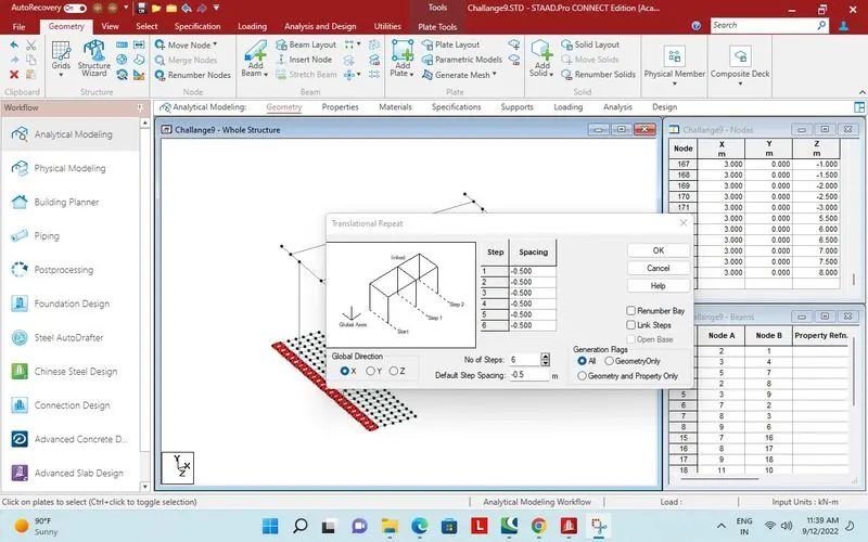
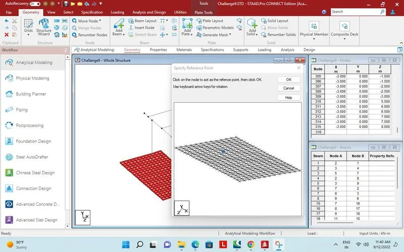
Plates for foundation copied and prepared to paste with reference point.
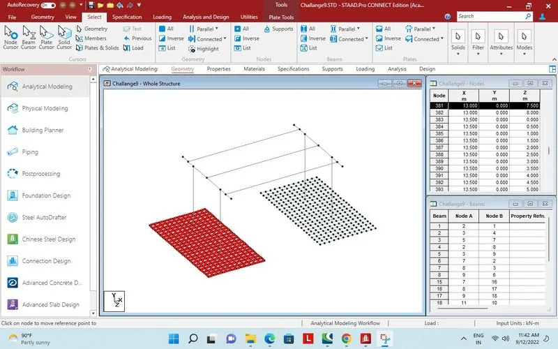
2nd foundation created.
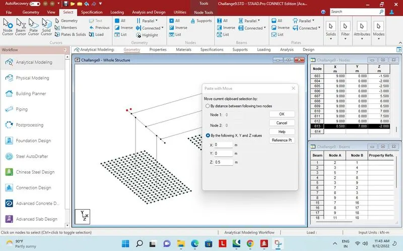
Nodes created for Deck at a distance of 0.5m.
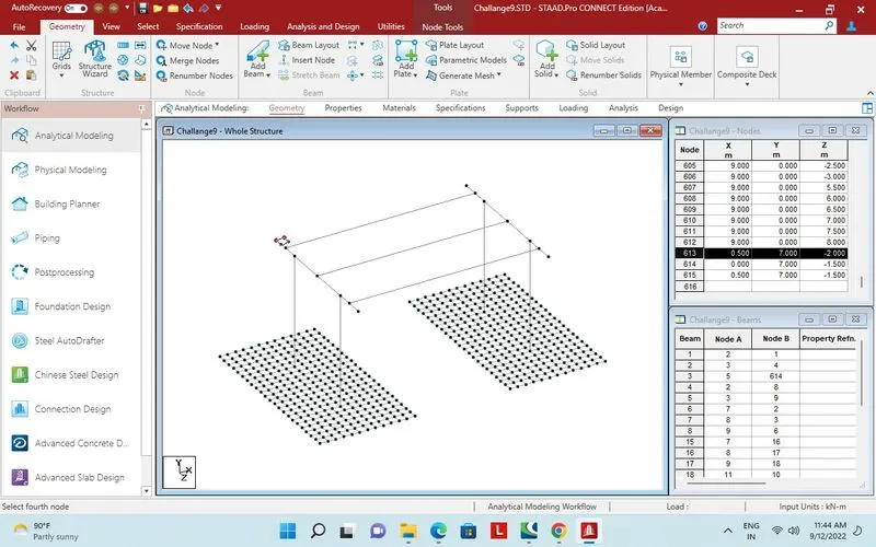
Plate created by joining four nodes.
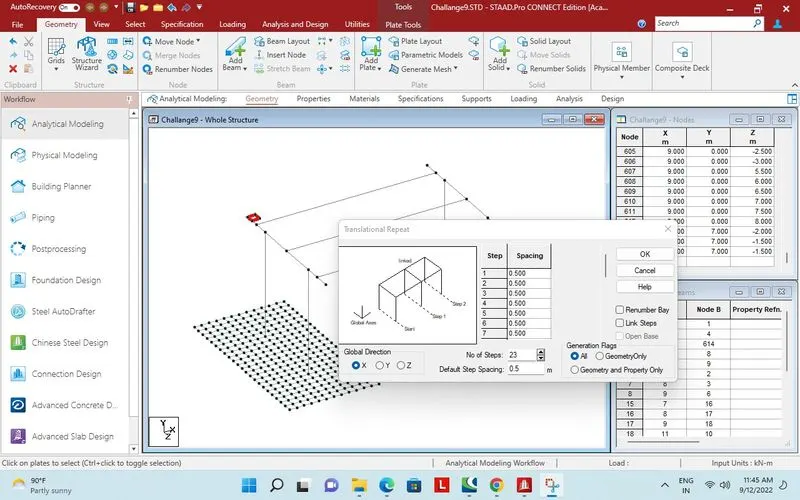
23 No in X direction translational repeat at a distance of 0.5m.
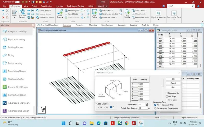
Plates created in X direction.
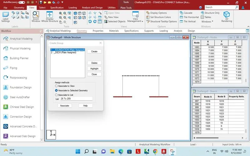
Group created for foundation and deck.
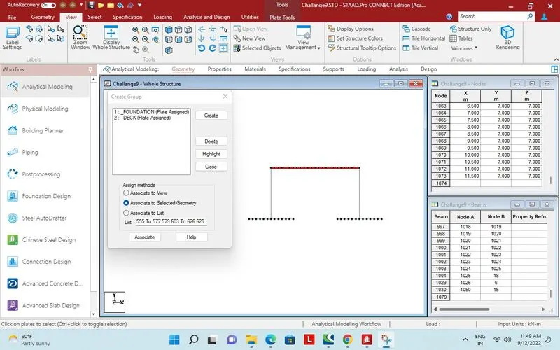
Plates assigned to deck.
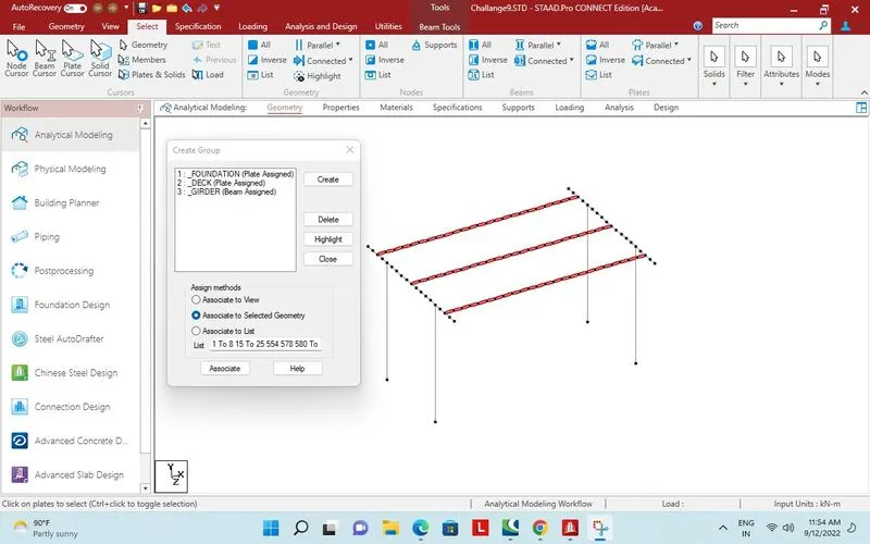
Girders assigned to group.
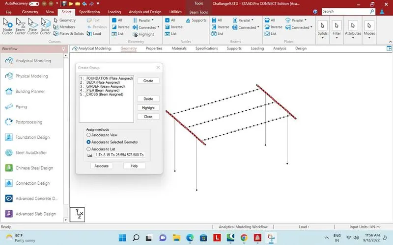
Cross beam assigned to group.
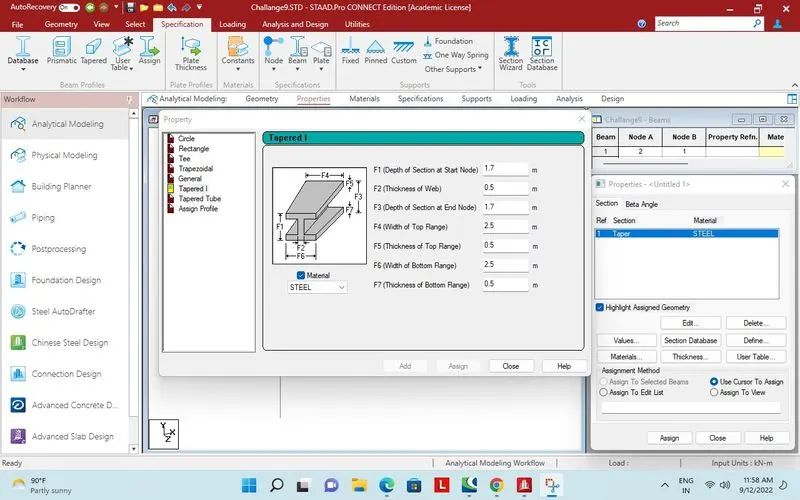
Property for girder.
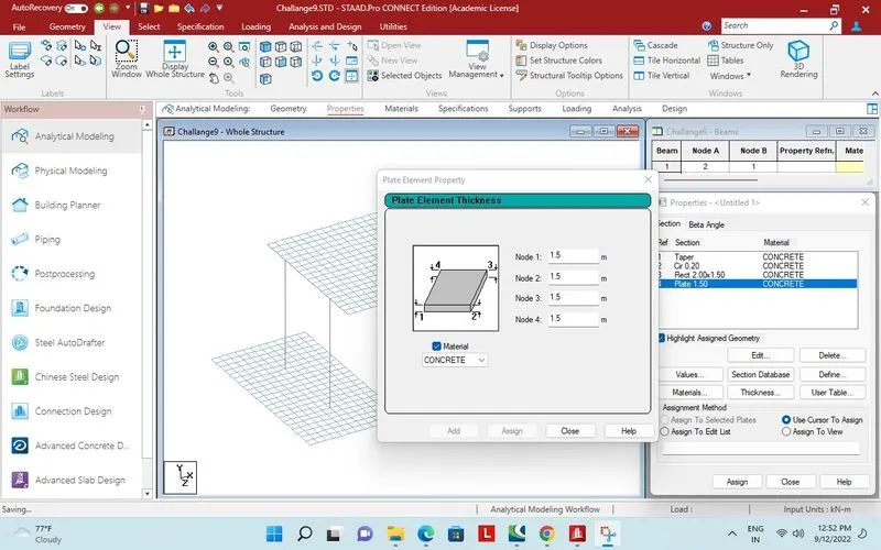
Plate thick ness for foundation.
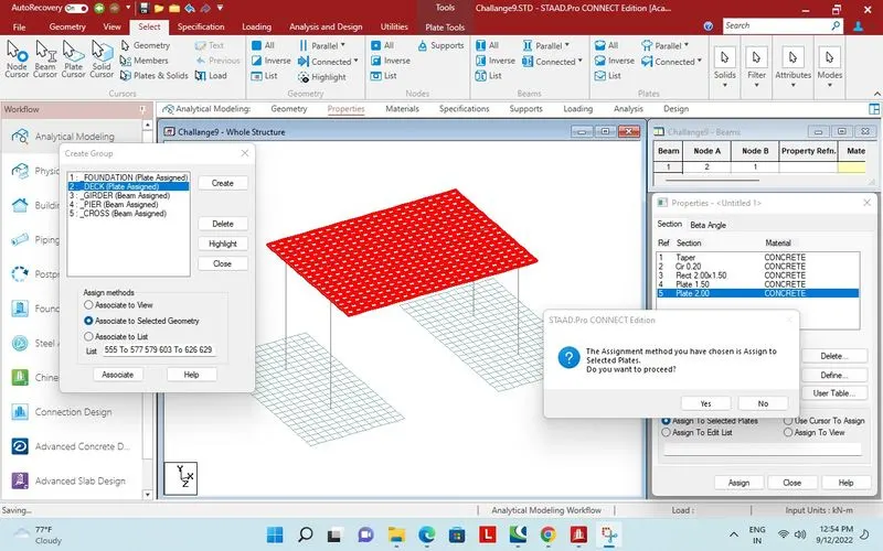
2m plate thickness assigned to deck.
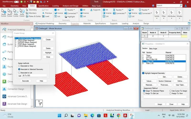
1.5m thickness assigned to foundation.
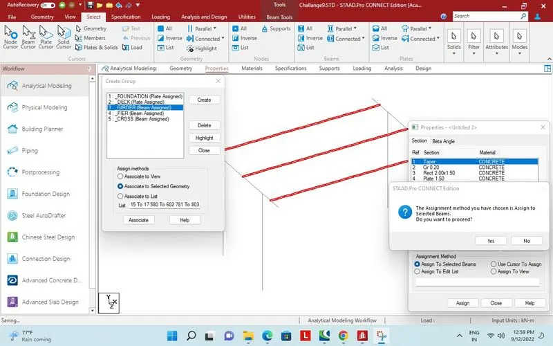
Property assigned to I girders.
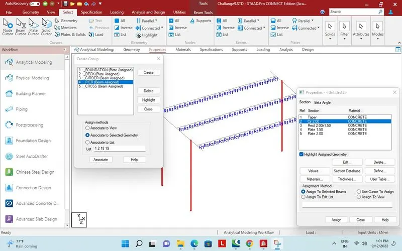
Property assigned to Pier.
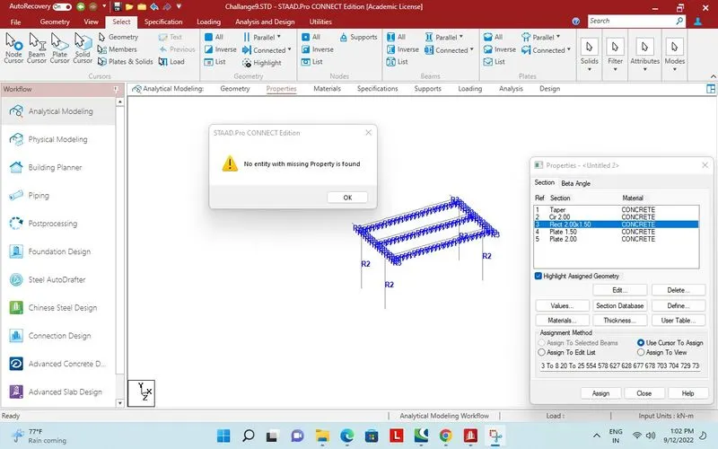
Missing property checked.
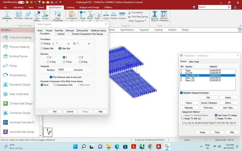
Support for foundation.
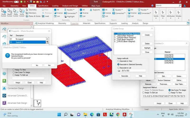
Assigned to selected plates.
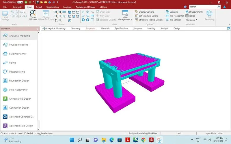
3d view of structure.
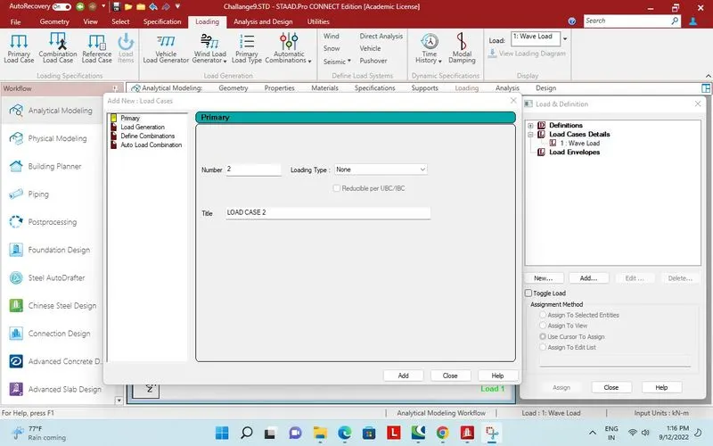
Wave load for load case 1.
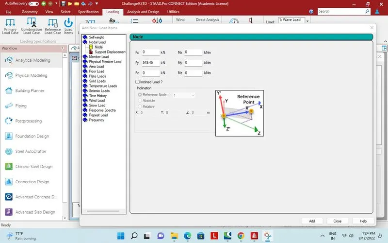
549.45kN vertical nodel load in y direction.
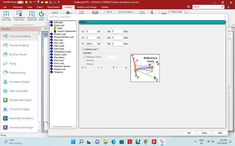 3353.40kN horizontal nodel load in Z direction.
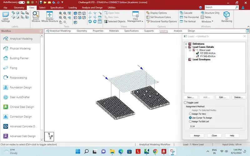
Horizontal wave load assigned.
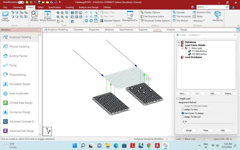
Vertical load applied.
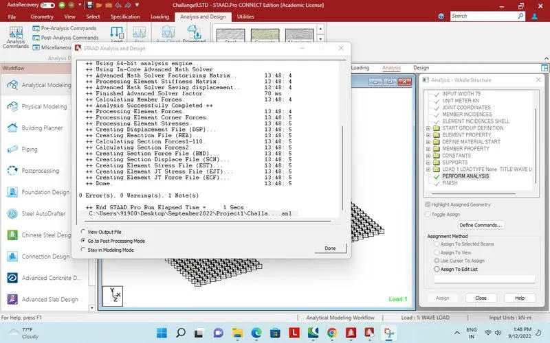
Analysis done successfully, with zero error and zero warning.
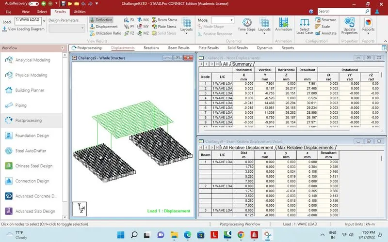
Structure in post processing mode with displacement behavior.
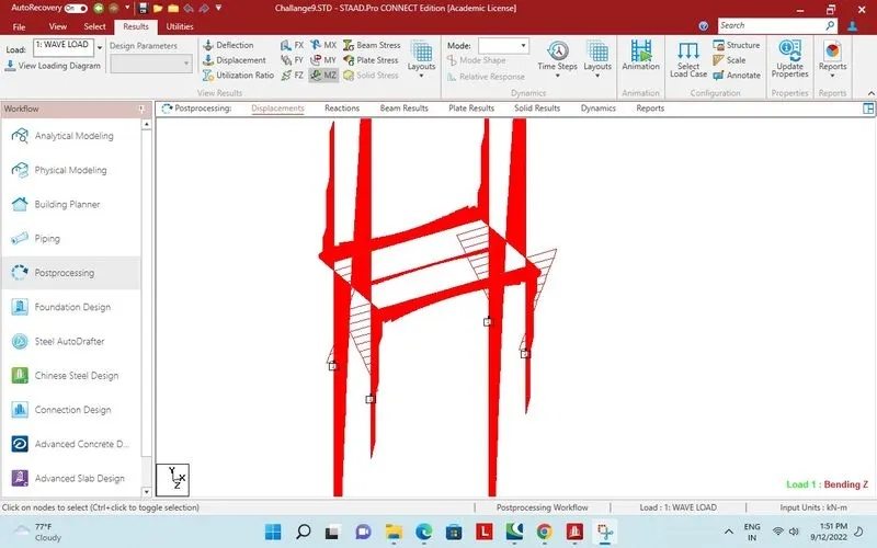
Bending moment MZ for beam structure whole.
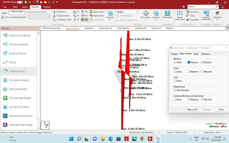
One bay with max bending moment annotate.
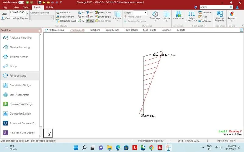
Max bending moment in1 Pier.
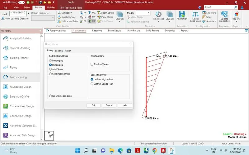
Pier selected for report.
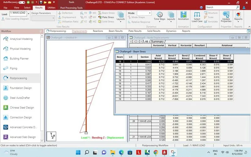
Report.