Week 4 Challenge
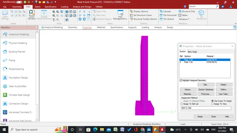
Abutment wall 1m wide 5m long with 1m deep raft created
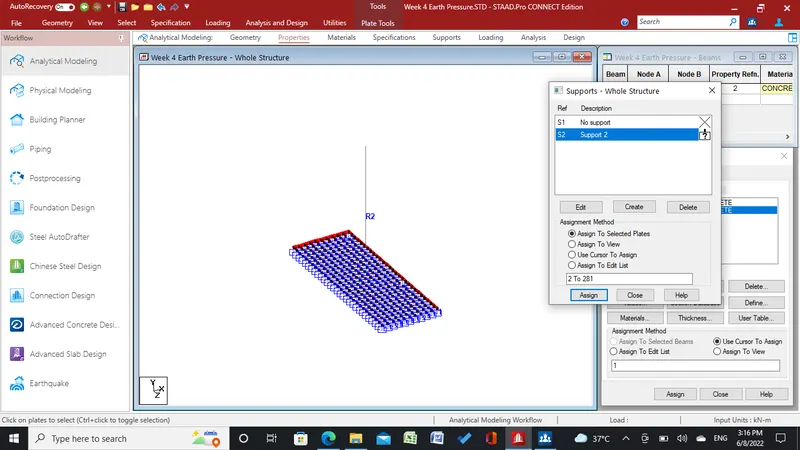
Foundation support created and assigned
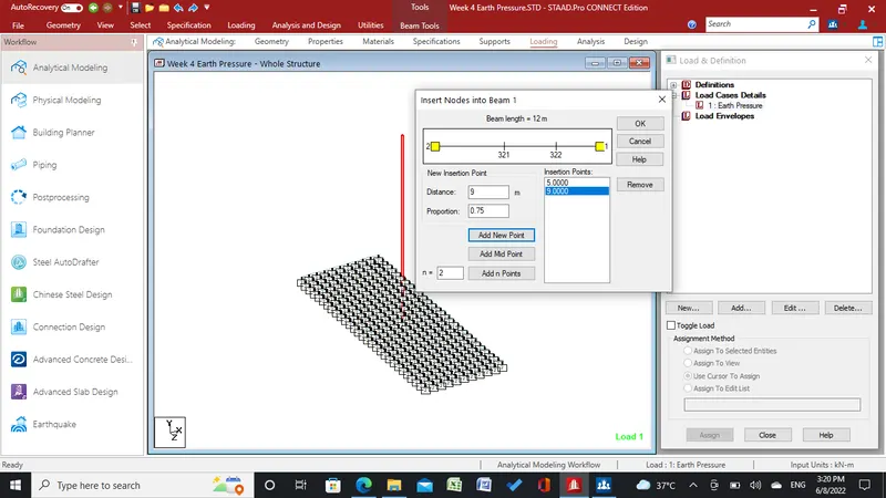
Node for back fill height and GL inserted
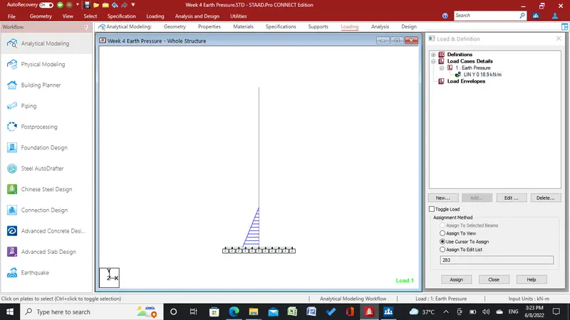
Linerly varrying earth pressure created opposit of back fill side and assigned to beam up to GL level
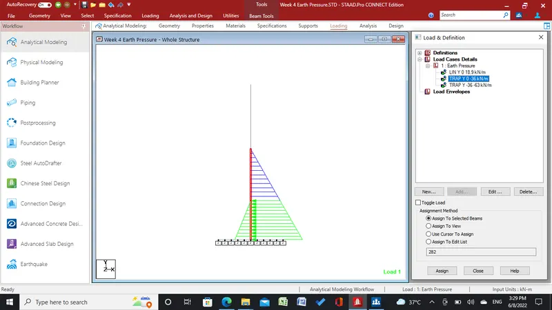
Earth pressure back fill side created and assigned to beam up to back fill heigt
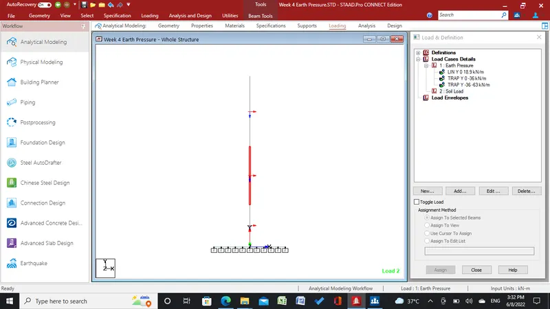
Knowing local axis is necessary to assign load in proper direction
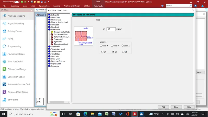
Soil load of back fill act as plate load
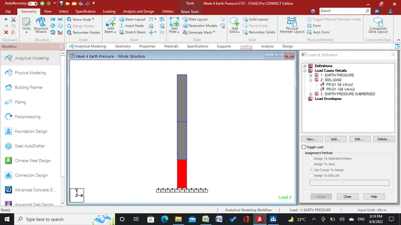
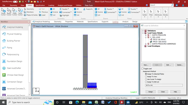
Soil load is applied out side of abutment wall. Viewing full structure drawing is must to apply load on remaining plates
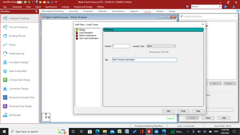
Earth pressure for submerged soil added
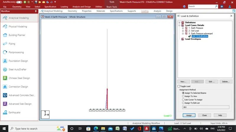
Earth pressure up to Water table/GL added and assigned
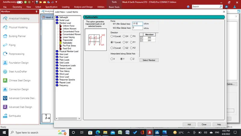
For to apply load on both beam height Hydraulic selected on member load
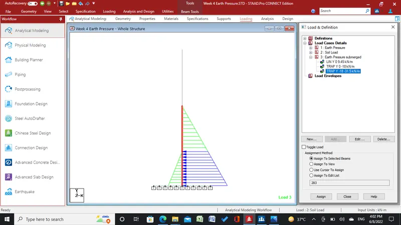
Load applied on back fill side
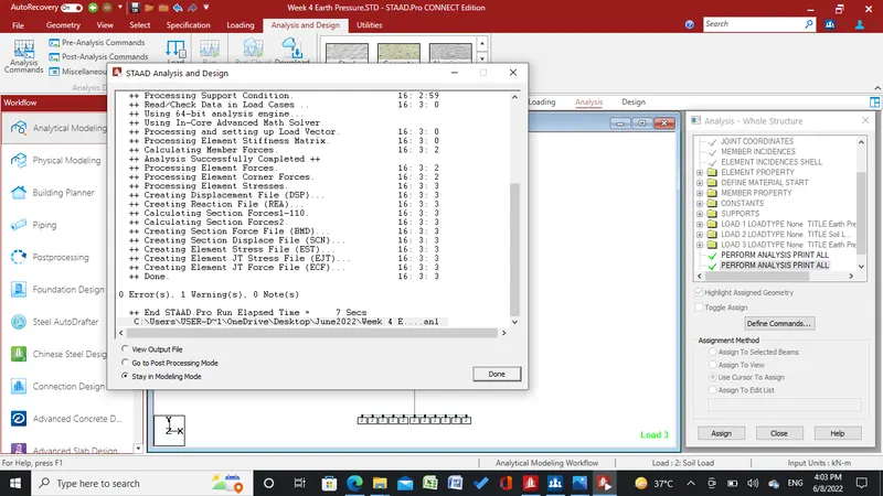
Analysis run
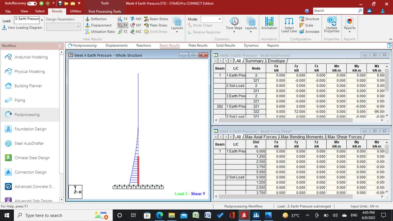
Result checked as shear y direction
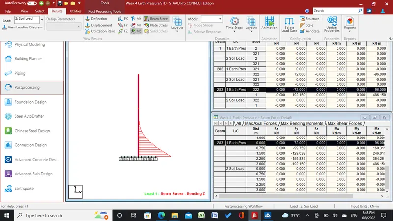
Bending moment z direction