Week 9 Challenge
Aim and Introduction :-
- The aim of this challenge is to determine/calculate the scouring depth and fixing the span arrangement for the requirement of clear linear waterways.
- To propose the foundation of abutment and pier lform the given data.
- To calculate the forces on the foundation as per IRC-6.
- So first of all for calculating the scouring depth IRC 78 need to be followed then after applying the loads on the structure the foundation is being decided.
- The loads is to be taken as per the provisions of relevant manual. ( IRC-6-2014).
1. In a river of linear waterway 90 m and design discharge as 700 cumec and having silt factor as 1 . Fix the span and type of foundation if HFL is 3 m from the ground.
Velocity of water 1.2m/sec
Calculate the forces as per IRC 6 on the foundation and propose the foundation.
- assume simply supported bridges
- continuous bridge.
ANS:
- Data Given:
- Linear waterway = 90m
- Design Discharge = 700 Cumec
- Silt Factor= 1
- HFL = 3m
- Velocity = 1.2m/sec
- FRL = 100 m
- OGL = 93.5 m
- Vertical Capacity = 250 tonnes (for 1.2m dia pile)
- Horizontal capacity = 35 tonnes (for 1.2 m dia pile)
- Well capacity - 50 tonnes /m2 (for 6m dia well)
- - 60 tonnes /m2 (for 7m dia well)
- - 70 tonnes /m2 (for 8m dia well)
SCOUR CALCULATION BY USING LACEY'S EQUATION Linear Waterway = 90 m Highest ground level = 93.500 m Highest Flood Level at the bridge site = 96.500 m Length of Bridge Proposed = 90 m Considering span length = 30 m No. of span = 3 Nos. Design Discharge (Q) = 700.00 Cumec Designed discharge as per IRC:78-2014 = 910.00 Cumec Discharge per meter width (Db) =910/90 = 10.11 Cumec Silt Factor (Ksf) = 1.00 Mean Depth of Scour (dsm) = 1.34 (Db2/Ksf) 1/3 = 6.26 m FOR ABUTMENT Maximum Depth of Scour for Abutment = 1.27 x dsm = 7.945 m Grip length = 2.648 m Maximum Scour Level for Abutment = 88.555 m Depth of foundation = 4.945 m FOR PIER Maximum Depth of Scour for Pier = 2.0 x dsm = 12.512 m Grip length = 4.171 m Maximum Scour Level for Pier = 83.988 m Depth of foundation = 9.512 m
- All the loads acting on the abutment as per IRC 6 is need to be determined for a single span.
- DL -
- Super structure -
- cross sectional area of the section at support - 7.901 Sqm ( Determined Form Auto CAD)
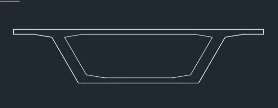
- cross sectional area of the section at Mid - 6.913 Sqm ( Determined Form Auto CAD)
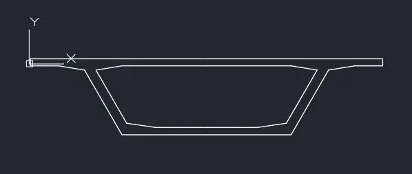
- Extend length of girder at support section - 10.0 m
- Extend length of girder at mid section - 10.0 m
- cross sectional area of the section at support - 7.901 Sqm ( Determined Form Auto CAD)
- So Total load = Volume x Unit Wt. = ( 2 x 7.901 x 10.00 + 1 x 10.00 x 6.913) x 2.5t/m3= 567.875 t
- Substructure-
- Total wt. Pier Cap = 1 x 12.5 x 2.5 x 2.5 = 78.125 t
- Total wt of Pedestal = 0.8 x 0.8 x 0.4 x 2.5 x 3 = 1.92 t
- Wt of pier = (9.512+0.5) x 5 x 4.15 x 1.5 = 312.875t
- Super structure -
- SIDL
- Crash Barrier -
- Considering the wt of Crash barrier = 10 KN/m =1t/m
- So total load due to CB = 2 x 1 x 30 = 60 t
- Wearing Coat-
- Considering the unit wt of WC = 2 t/m
- Thickness of wearing coat = 0.065 mm
- Total load due to WC = 12.5 x 30 x 0.065 x 2 = 48.75t
- Dirt Wall -
- Total Load = 2.5x 12.5 x 0.4 x 2.5 =31.25 t
- Crash Barrier -
- Vehicle Load -
- Considering 70R loading total load = 100 t
- DL -
- So Total vertical loads acting on Pier = (567.875+78.125+ 1.92 +312.875+60+48.75+31.25+100) = 1200 t
- Increase for seismic case consideration = 25%
- Total Vertical design load = 1200 x 1.25 = 1500 t
For pier according to the pile capacity the no. of 1.2m dia pile required = 1500/250 = 6 No.s
1)What is zero shear point and if there is more scour at region what will be the effect of that on zero shear point.
zero shear point
- The points other than the extreme ends of a beam in a beam at which B.M. is zero are called points of contraflexure or inflexion. The point at which we get zero shear force we get the maximum bending moment of that section/beam at that point.
- If there is more scour at then there may be the possibiility arrises for settlement of the structure. Due to settlement the magnitude of B.M. increases phenomenonly at the maximum B.M. point i.e zero shear point. for which the structure tends to failure.
- Alos due to scouring the buckling may arises in the foundation due to which failure may occure.
Define the Liquefaction and its effects, how it can affect foundation. Also list the remedial measures for the same. How it is different from scouring?
- Liquefaction takes place when loosely packed, water-logged sediments at or near the ground surface lose their strength in response to strong ground shaking. Liquefaction occurring beneath buildings and other structures can cause major damage during earthquakes.
- Liquefaction is basically not a kind/type of soil. It is a condition of soil when the behaves as a liquid.
- Liquefaction occures in fully saturated and cohession less soil.
Liquefaction affects the foundation of the structure the most. So there is basically two possibilities that
- Liquefaction in deep foundation
- Liquefaction in deep foundation is occures due to the following reasons.
- Lateral Spreading of the ground- The movement of soil in the downward direction after the soil has been liquefied due to earthquake shaking is termed as lateral spreading.Pile are used for stabilization.These piles commonly need to withstand substantial lateral forces generated by soil passive pressure while the entire slope suffer lateral spreading.
- Buckling of Piles-Piles are considerably long element and the soil around it offers an excellent support. However, if the soil is soft and the supported load is large, then it is likely that the pile would buckle. It should be known that buckling of pile foundation.When the soil around the pile foundation liquefied due to earthquake affects, then the loss of lateral support is highly probable and consequently skin friction would no longer occur.
- Liquefaction in deep foundation is occures due to the following reasons.
- Liquefaction in shallow foundation
- It is important the all foundation elements in a shallow foundation are tied together to make the foundation move or settle uniformly, thus decreases the amount of shear force induced in the structure elements resting upon the foundation.
- Remedial Measures:
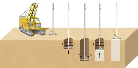
- Mitigation by deep soil mixing method - Deep soil mixing (DSM) is a ground improvement technique that improves soft, high moisture clays, peats, and other weak soils, by mechanically mixing them with dry cementitious binder.
- Advantages
- Increase global stability
- Mitigate liquefaction
- Increase bearing capacity
-
Decrease settlement
-
Fixate contaminants in situ
- Advantages
- Compaction, Permeation, and Jet Grouting
- Compaction Grouting
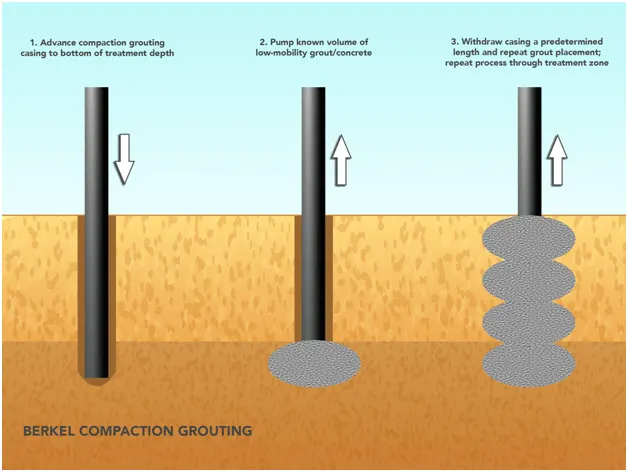
Compaction Grouting involves injection of low mobility grout via drill casings that are drilled/driven to pre-set depths. The grout, usually comprised of cement, sand, fly ash and water, is placed from the bottom-up with pressure based criteria. After each consecutive stage, the drill casing is lifted upwards until it is entirely taken out. Compaction Grouting is also commonly known as Low Mobility Grouting.
- Fracture Grouting
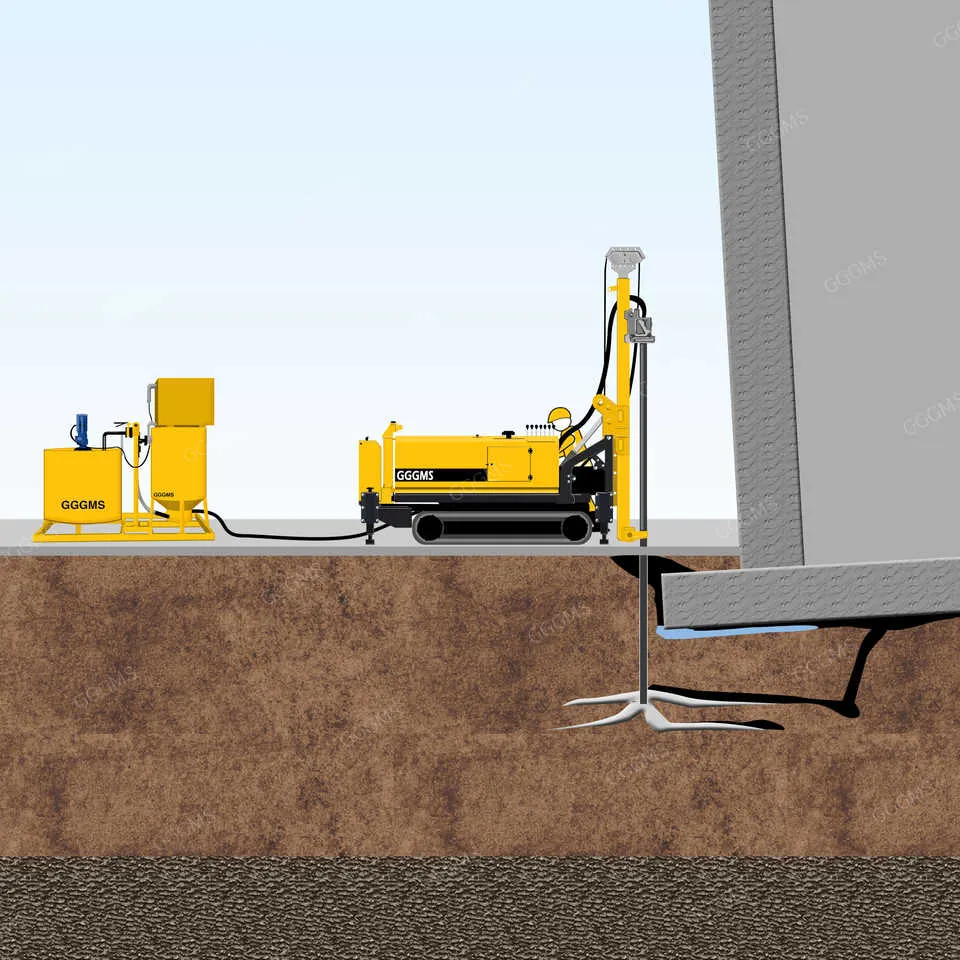
Fracture grouting uses a low viscosity grout that splits through the ground by hydraulic fracturing and penetrates into the fractures. The in situ soils are displaced and soil immediately next to the fractures are densified, but to a lesser extent than compaction grouting. Fracture grouting can also be referred to as compensation grouting and is commonly used to relevel structures.
- Jet Grouting
Jet grouting uses a high-pressure ‘jet’ of either grout, water, air or a combination to erode soil whilst simultaneously injecting grout into the soil through a ‘jet monitor’. The specially designed drill stem and monitor are raised and rotated at the same time to combine the grout with the original soil to form ‘soilcrete’. The end product is cemented round columns and is basically effective in any soil but not necessarily.
- Compaction Grouting
- Drain Pile technique
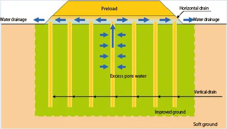
- The earthquake drain ground improvement method minimizes bearing capacity failures and settlement during and immediately after a seismic event. It mitigates liquefaction by limiting excess pore pressures generated during seismic events to levels less than those that could trigger liquefaction.
- Stone Column
-
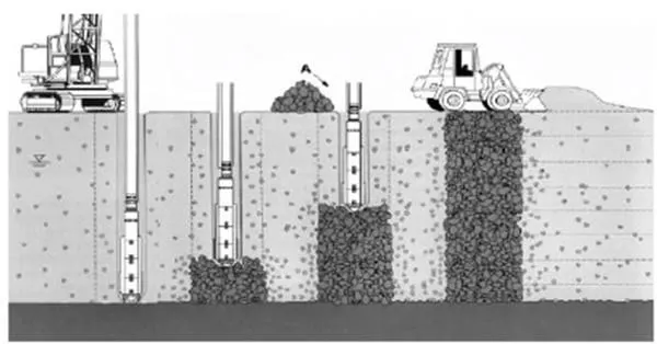
Stone columns are columns of gravel constructed in the ground.Stone columns can be constructed by the vibro-compaction method. In this approach the steel casing is driven into the soil and gravel is filled in from the top and tamped with a drop hammer as the steel is successively withdrawn.
-
-
How soil Liquefaction is different from scouring?
-
Soil liquefaction occurs when a cohesionless saturated or partially saturated soil substantially loses strength and stiffness in response to an applied stress such as shaking during an earthquake or other sudden change in stress condition, in which material that is ordinarily a solid behaves like a liquid.
-
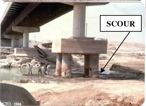
scour is the engineering term for the erosion of soil surrounding a bridge foundation (piers and abutments). Bridge scour occurs when fast-moving water around a bridge removes sediment from around the bridge foundation, leaving behind scour holes.
-