Week 2 Challenge
Aim and Introduction:-
- The aim of this challenge is to calculate all types of dead loads and live loadd coming on to it and to analyse the effect of the loading on the T-Beam girder in staad Pro.
- So first of all the dead load is to be calculated from the given section and the live load is to be analyzed by diffrent type of class of vehicles as per the code considering class A and 70 R vehicle with considering parapet wall on it. The DL is calculated as per meter run loading.
- Then the model will be created in Staad pro. and the reactions due to the loading is being analyzed by considering the girder and deckslab as given.
Data Given :-
Width of Deck Slab =7 m
Span of Bridge = 24 m
Pier Size (Circular)=2.0 m
Seismic Zone = III
Wind Speed =42 Km/hr
Unit Wt. of Soil = 18 KN/m3
Unit Wt. of Concrete = 25 KN/m3
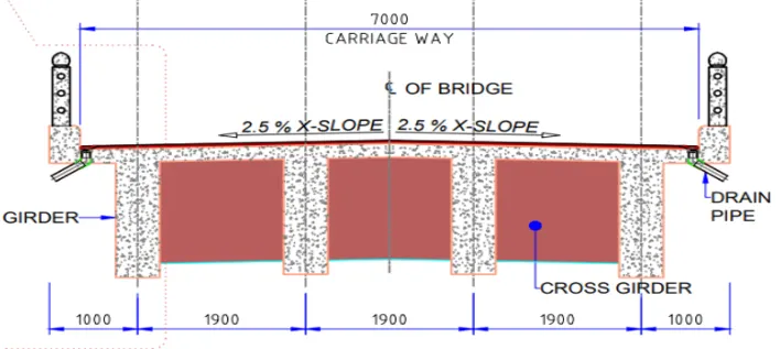
Dead Load Calculation :
Calculation of Dead load of single main girder
Ht. of Girder = 1.9m - 0.2m = 1.7m
Width of Girder = 0.5 m
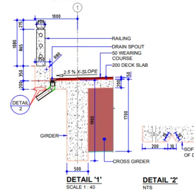
Total C/S Area of a single girder
=1.7m x 0.5m = 0.85 Sqm
|
Self Wt. of girder = |
|||
|
C/S Area |
x |
Unit Wt. of Conc. |
|
|
= |
0.85 |
x |
25 |
|
= |
21.25 |
KN/m |
|
Calculation of Dead load of single cross girder
Ht. of Girder = 1.7m - 0.2m = 1.5m
Width of Girder = 0.3 m
Total C/S Area of a single girder
=1.5m x 0.3m = 0.45 Sqm
|
Self Wt. of girder = |
|||
|
C/S Area |
x |
Unit Wt. of Conc. |
|
|
= |
0.45 |
x |
25 |
|
= |
11.25 |
KN/m |
Slf Wt. of parapet
(i)Base Part -
Dimension = 0.35m x 0.35m
Area = 0.1225 sqm
(ii) Shaft part -
Dimension = 0.865m x 0.20m
Area = 0.173 sqm
(ii) Top part -
Dimension = 0.215 Dia
Area = 0.037 sqm
Total Area of the Parapet
= 0.1225 + 0.173 +0.037 = 0.3325 sqm
Slf wt. Parapet = 0.3325 x 25 = 8.3125 KN/m
Considering the wt. of the parapet wall on both the side girder
Total Dead Load on Side Girder = 21.25+8.3125
= 29.57 KN/m
= 30 KN/m
Slf Wt. of Deck Slab:
= 0.2 m x 25 KN/m3
= 5 KN/m2
ANALYSIS IN STAAD Pro.
The model is created in STAAD Pro. For analysis and the type of loads coming on to it is considered during the analysis.
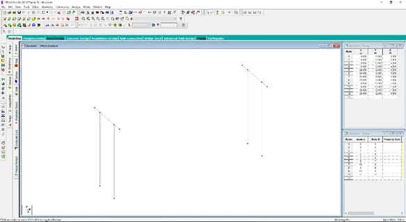
The pier and pier cap has been drawn.
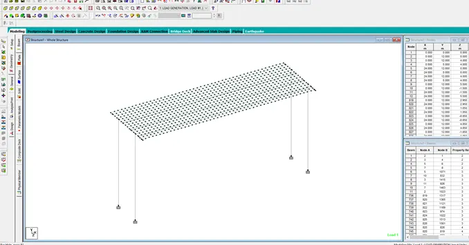
The whole structure as per given components as pier, main girder, cross girder & deck slab has been drawn.
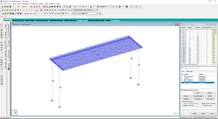
The dimensions of all the components has been assigned as required.
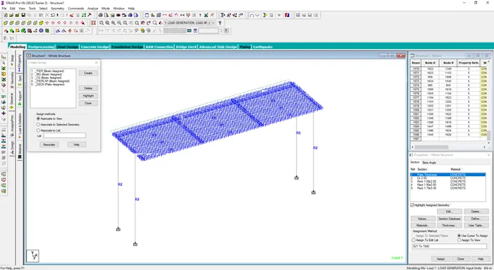
Groups has been assigned for individual components of bridge.
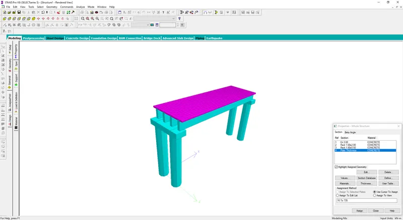
- The 3D render view of the model.
Load & Definations
Vehicle definations for class A, Class B & 70R has been given.

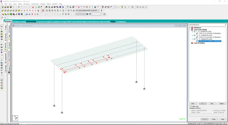
- Load Case details of the type of vehicle loading has been assigned.
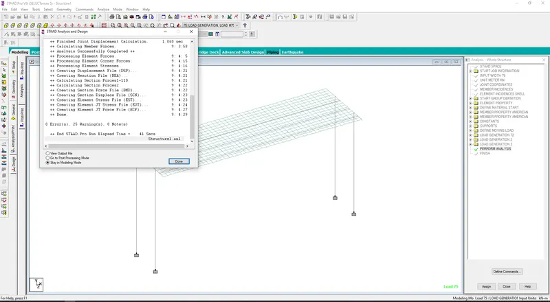
The Model has been analyzed
RESULTS
- Reactions
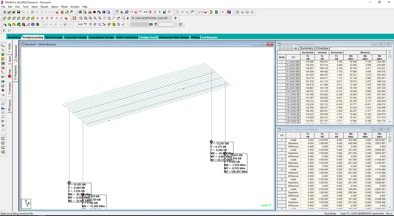
- Moments about X-axis and Z-axis.
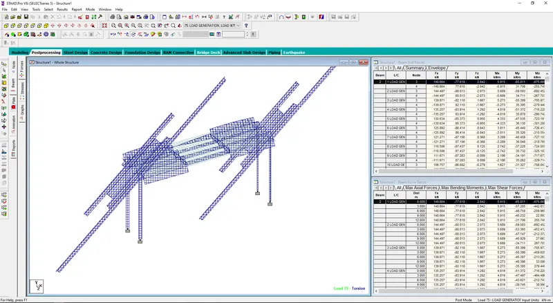
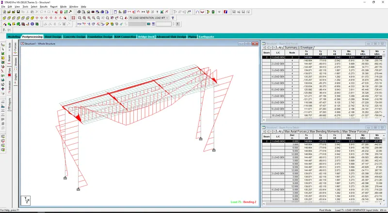
- Beam Stress
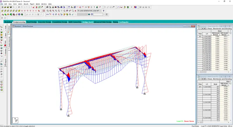
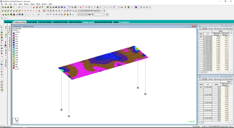
- Plate Stress for all load combinations has been analyzed.