Week 9 - Challenge 3 - Bumper
BUMPER DESIGN
CREATION OF TOOLING AXIS
1) As the bumper is a more complex design we are not supposed to create tooling axis in bisecting method.
2) First of all check for the possibility tooling direction in all axis.
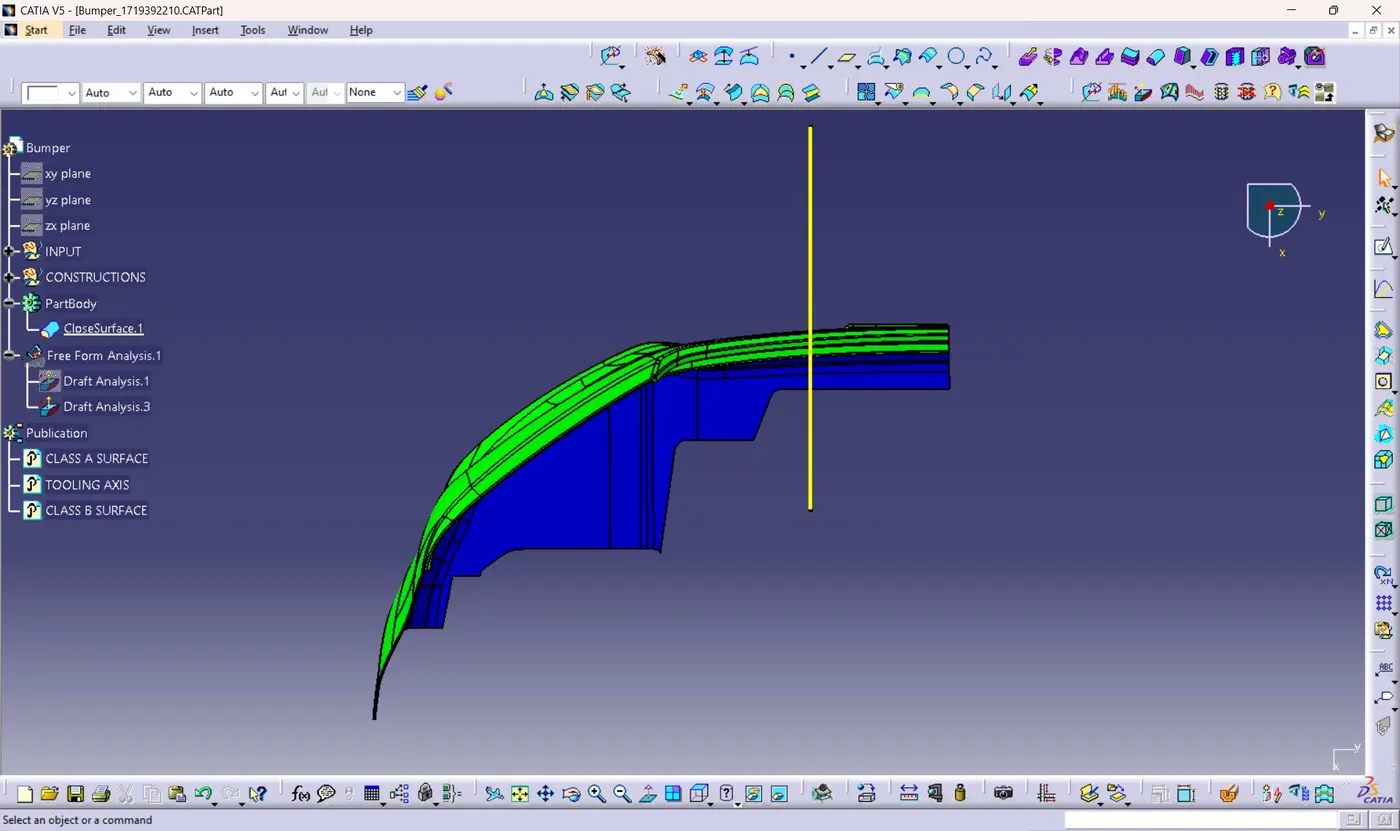
3) Here tooling direction is very much possible in X direction. All the surface patches are clearly visible through X direction.
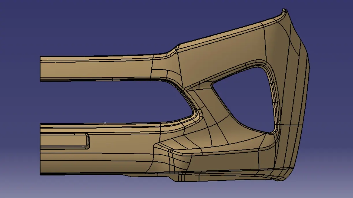
4) Create a point on any curve on the front side of bumper.
5) Draw a line through that point with direction X axis.
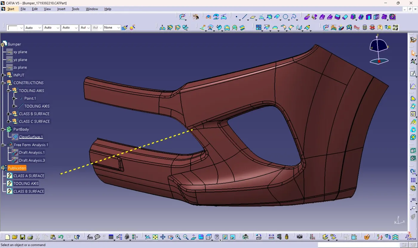
6) Here we have created a dummy tooling axis And want to check whether this is the actual tooling axis.
7) Inorder to know whether the dummy tooling axis will work we have to run a draft analysis .
DRAFT ANALYSIS OF CLASS A SURFACE
1) Click on the feature draft analysis option from Analysis toolbar.
2) Activate the compass by clicking on the compass symbol.
3) Drag the compass by clicking on the red dot in compass.
4) Align properly with the tooling axis.
5) Click on the lock option, so that the compass will be locked there.
6) Click on the surface and it will appear in draft angle colour codes.
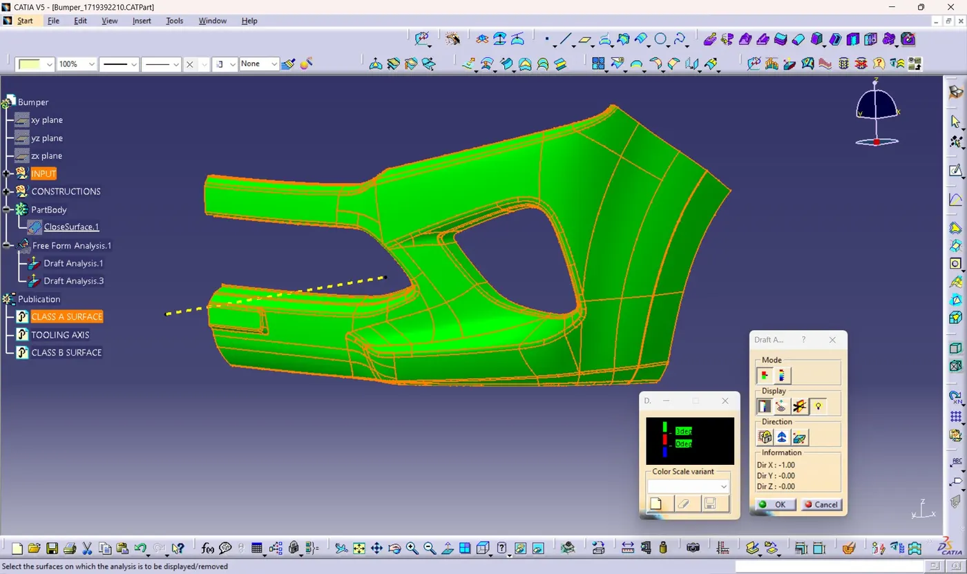
7) Here you can see that all the surafce patches appears in green colour which means that class A surfaces passes draft analysis with a minimum draft angle of 3 degrees through the selected dummy tooling axis.
8) Rename the Dummy Tooling axis as "Tooling Axis"
DRAFT ANALYSIS OF FINAL MODEL
1) After converting surface model into part model. We can check the draftability of final model.
2) Select feature Draft Analysis from Analysis toolbar.
3) Repeat the same steps which was done for Class A draft analysis until locking of compass.
4) After Locking the compass with tooling axis click on the component and it will appear in draft angle colour codes.
5) First will check with minimum draft angle as 3 degrees. 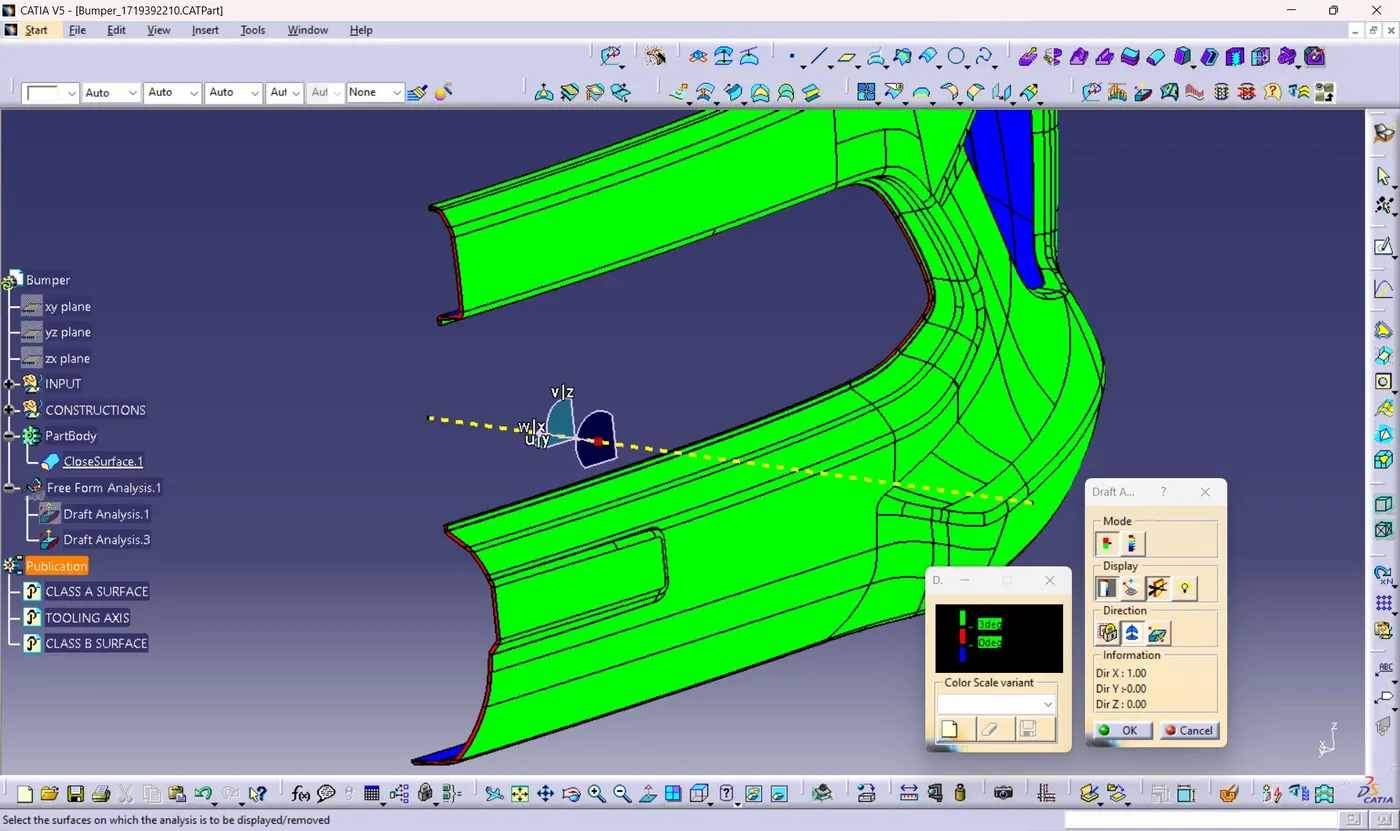
6) Here it's visible that some areas of class C surface appears in red colour which means its below minimum draft angle.
7) Check the angle of those areas using On the fly option from draft table.
8) The lowest angle which appears in some areas is 2.5 degrees.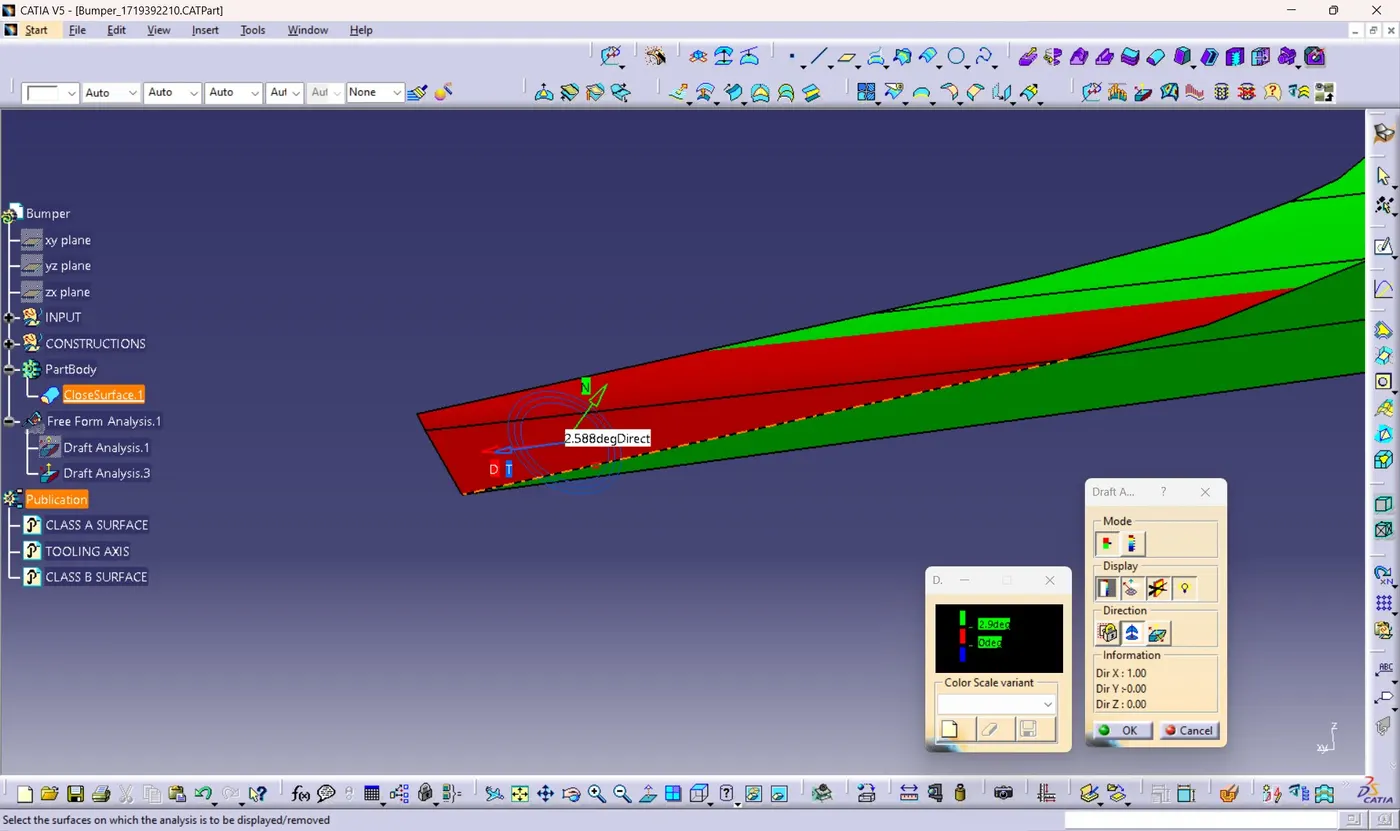
9) So reduce the minimum draft angle to 2.5 degrees and check again. 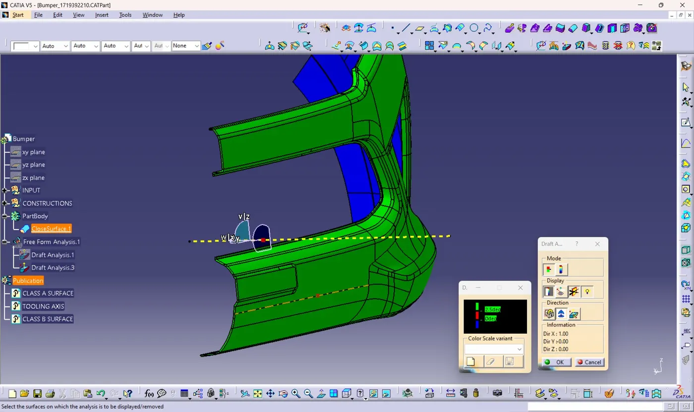
10) After reducing the minimum draft angle to 2.5 degrees all surface patches passes the draft analysis.
FINAL SOLID COMPONENT IN VARIOUS ORIENTATION WITH DRAFT COLOUR CODE
1) ISOMETRIC VIEW 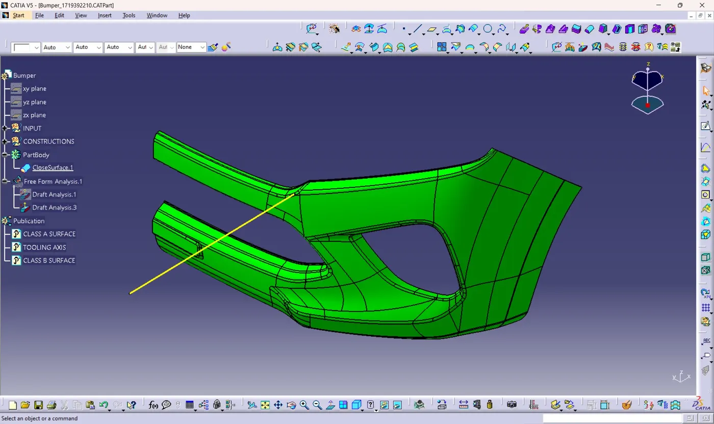
2) FRONT VIEW 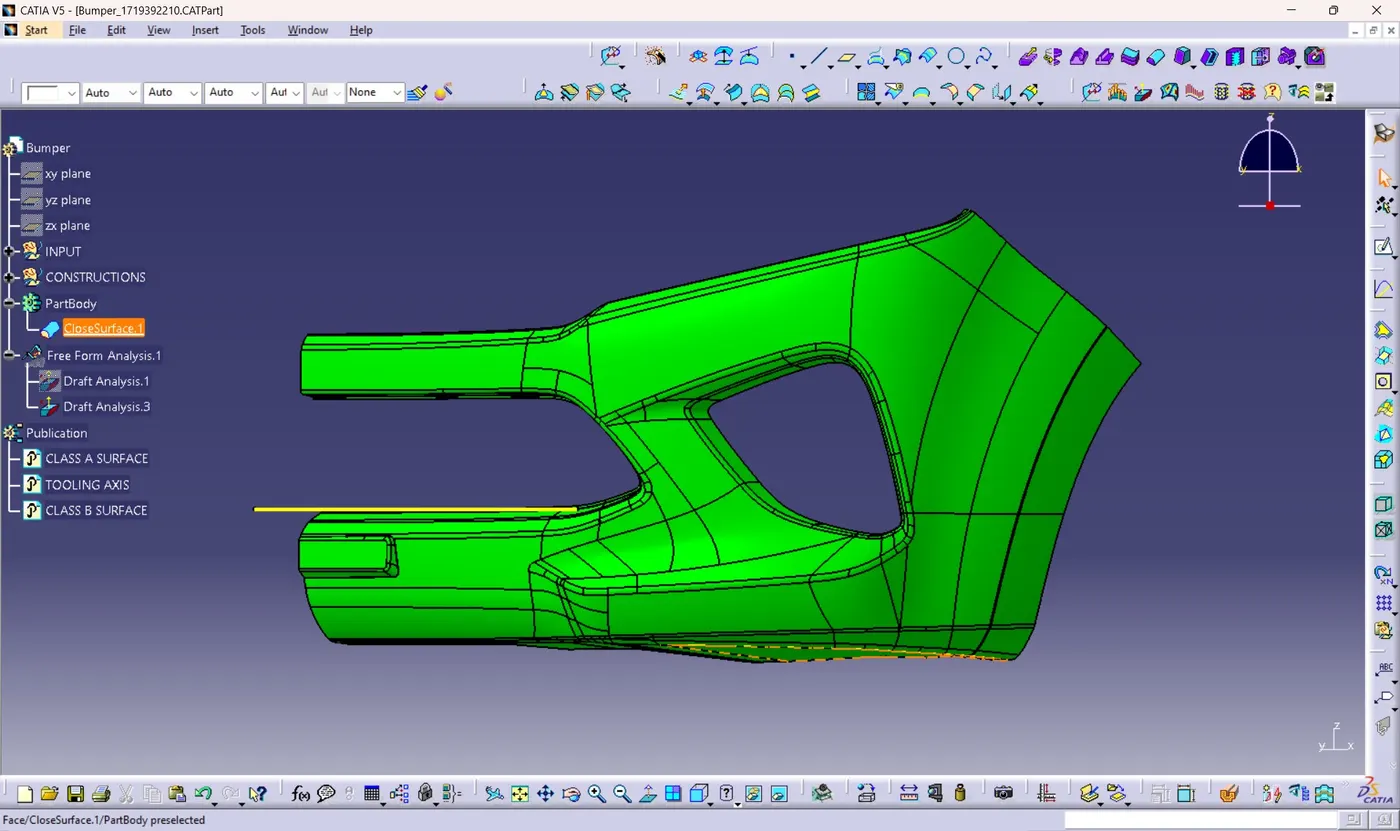
3) LEFT VIEW 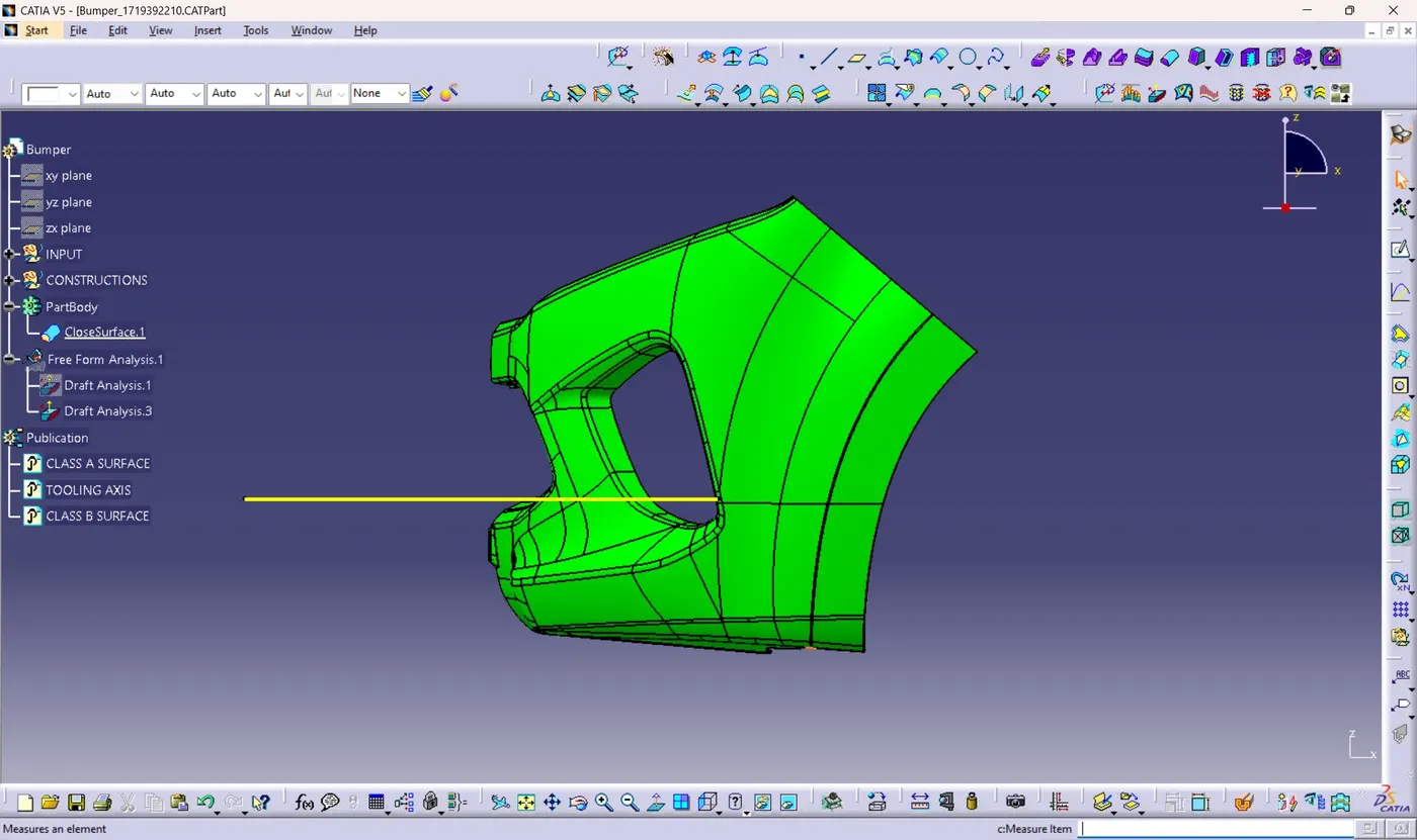
4) RIGHT VIEW
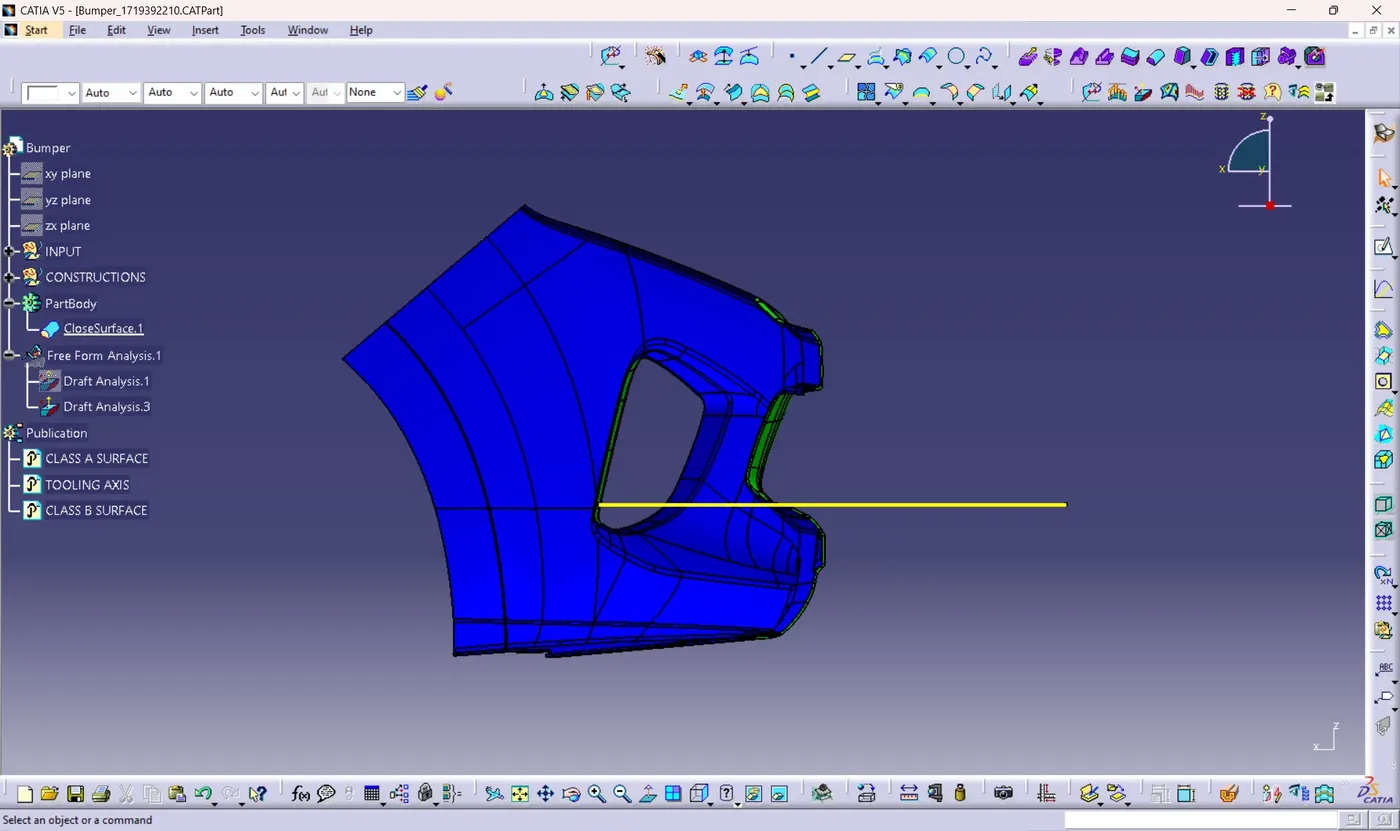
5) TOP VIEW