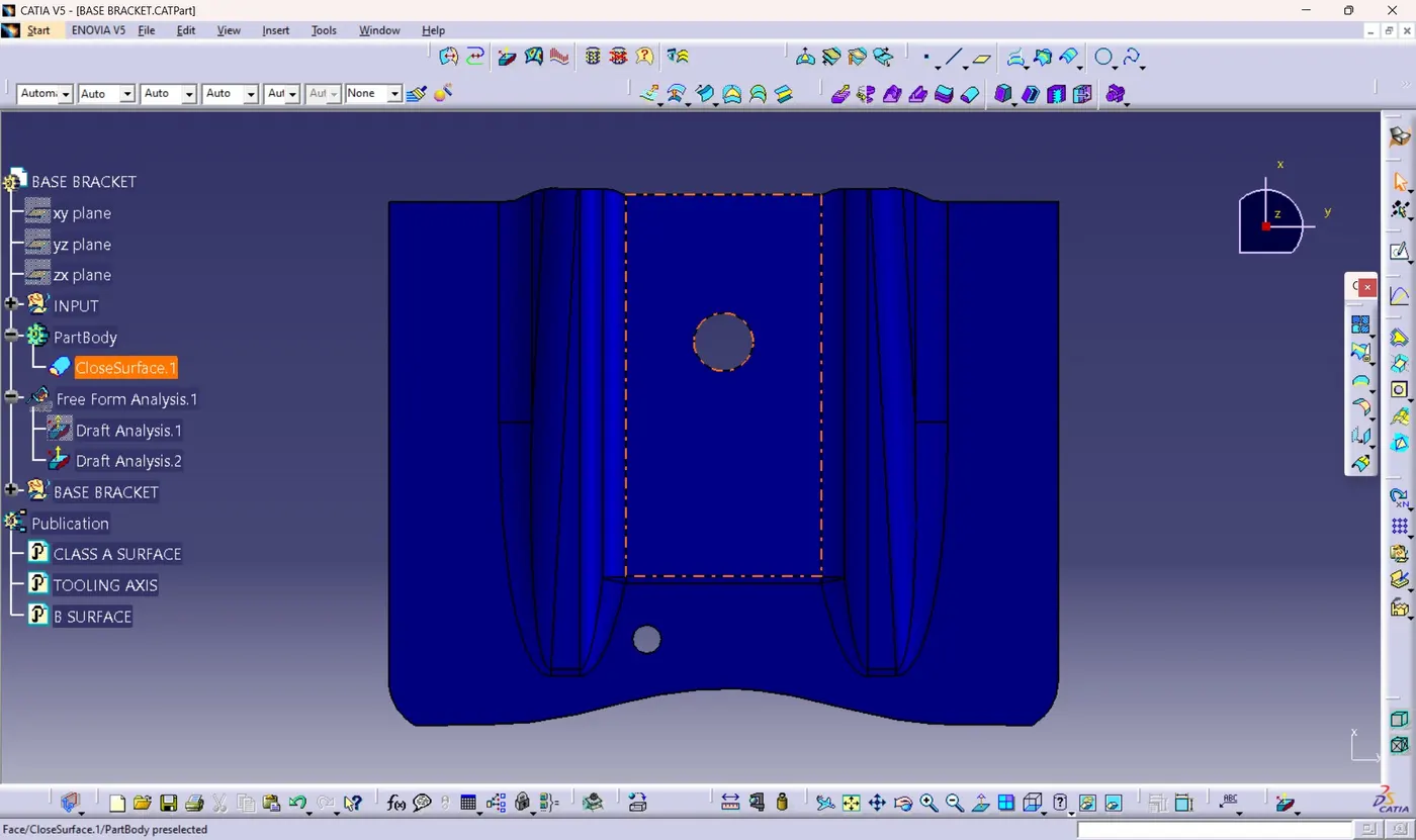
Week 9 - Challenge 1 - Base Bracket Design
BASE BRACKET DESIGINING
Creation of tooling axis :-
1) First of check for all possible directions which we can create tooling axis. After examining all directions Z axis direction came to be more appropriate for tooling axis.
2) Check for Holes or plane surface for creating dummy tooling axis. Here we have 2 ribs 2 flat surfaces and 2 holes.
3) Create a point on the center of circle and create a line through z axis direction which we can name as dummy tooling axis.
4) There are multiple fillet surfaces which we cannot take as reference for creating tooling axis. So we will take Plane surfaces as a reference.
5) Create a plane on the center of circle taking reference from YZ plane.
6) Create an intersect keeping YZ plane as reference .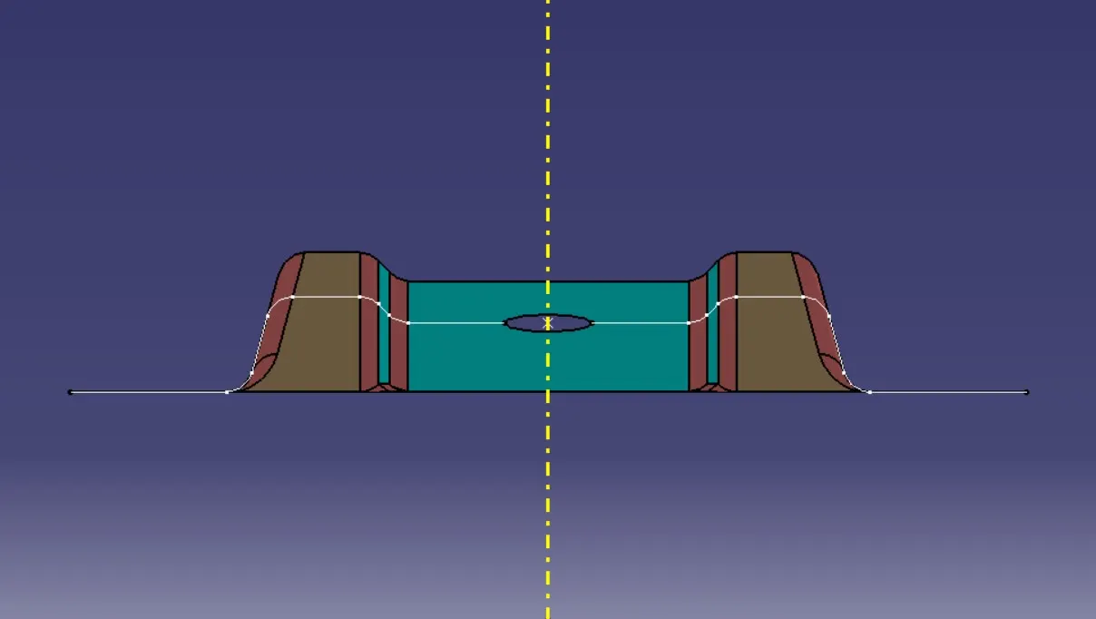
7) From the intersecting lines select straight lines parallel to the tooling direction (Z direction)and create extended lines using 2 points.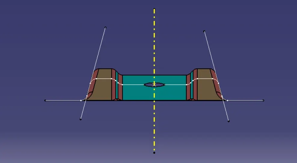
8) Remaining plane surfaces are having more than 45 degree inclination with tooling direction so dont want to consider those planes.
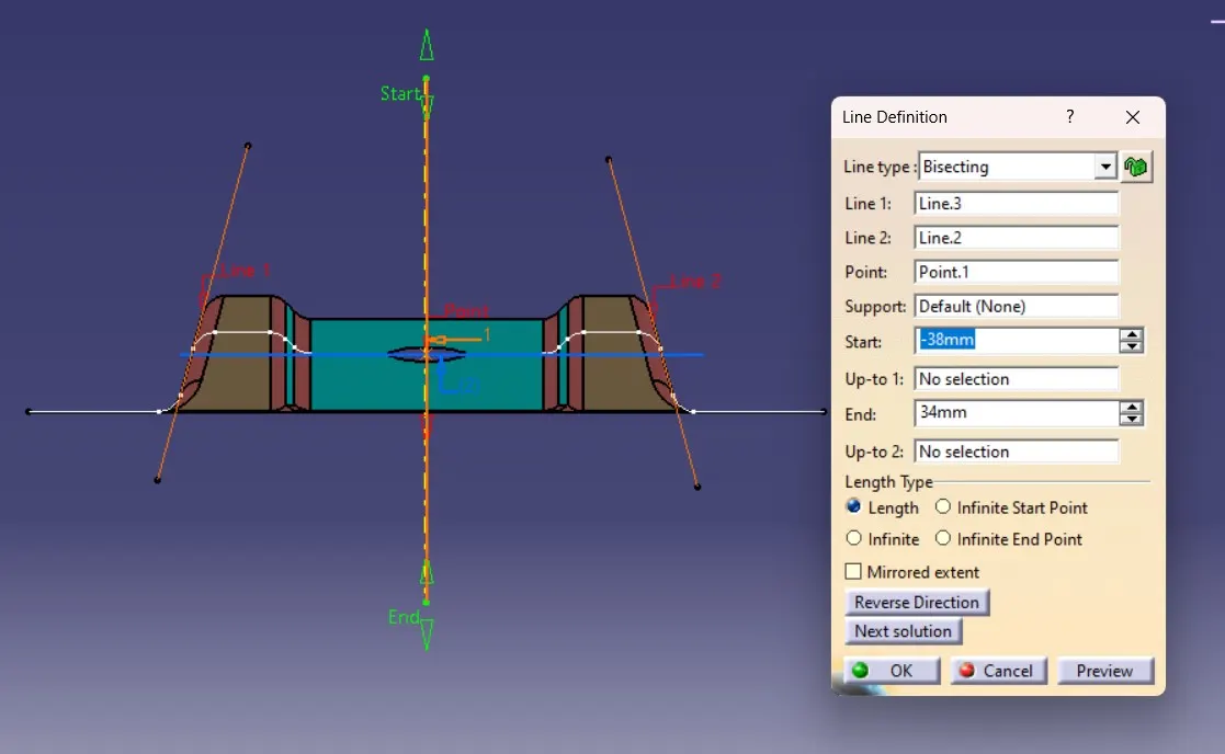
9) Create a bisecting line with those 2 lines and making that point as center.
10) The line create using bisecting method is our real Tooling axis. Make the line bold and mark with different colour.
Draft Analysis of Class A :-
1) Select Feature Draft analysis from Analysis toolbar.
2) From the toolbox click on the compass symbol. Drag and align the compass with tooling axis by clicking on the red dot in compass.
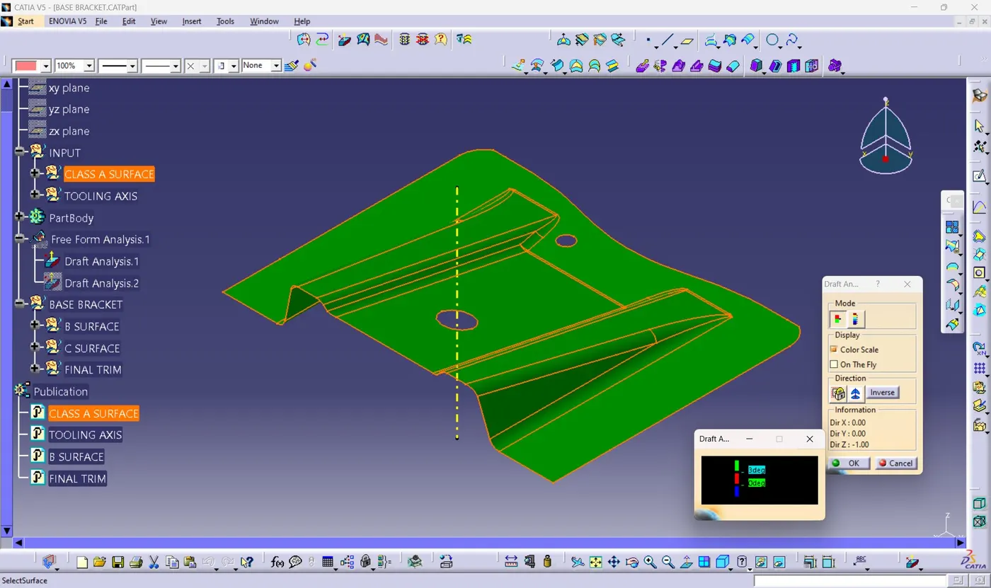
3) Click on the class A surface. The product will change the colour to a mix of green, red and blue. minimum draft angle is 3 degree.
4) Every part which appears more than 3 degree angle will be shown in green and whichever is between 0 and 3 will shown in red. The part which is in negative angle will appear in blue colour.
5) Here everything appears green. so its draft analysis is perfect and it can be send to production.
Draft Analysis of Plastic component :-
1) After making it as a solid component click on feature draft analysis and repeat the same steps done for class A
2) After fixing the compass click on the component.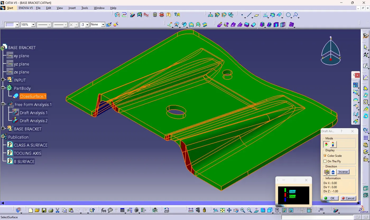
3) Here some areas are shown in red which means these areas are having an angle which is lower than 3 degree.
4) Our motive it is to make the material draftable. which means our component should have postive draft analysis. Then only this component will move for production.
5) Using In the fly option check the angles of red areas.
6) All Red areas angles are between 2.95 and 3 degree.
7) As the value is just a minute difference with 3 degree we can change the minimum draft angle to 2.95 which is acceptable in some cases. 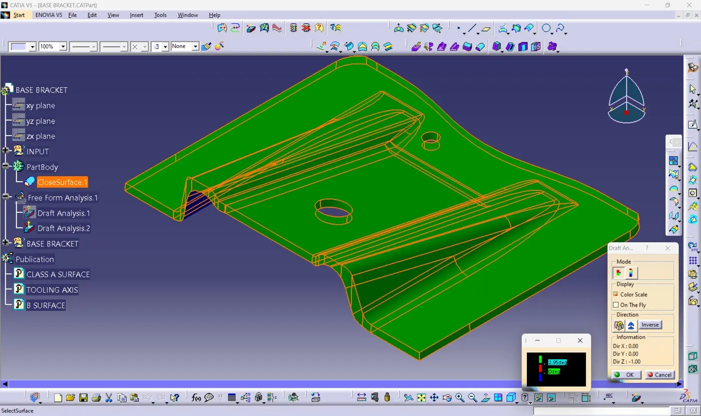
8) After changing draft angle everything appears to be in Green and we got a postive draft analysis report.
9) Bottom portion is shown in blue colour as the direction of tooling is from top to bottom. Ones you reverse the tooling direction the blue appears on the top of component.
Solid Model in different angles with colour code :-
1) Isometric view 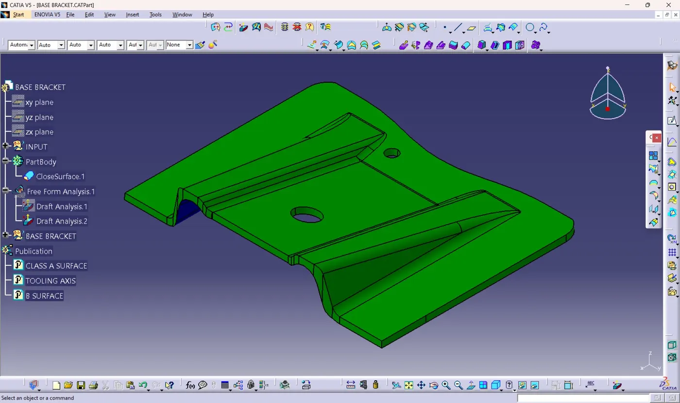
2) Front view 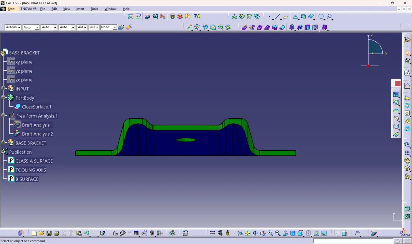
3) Side View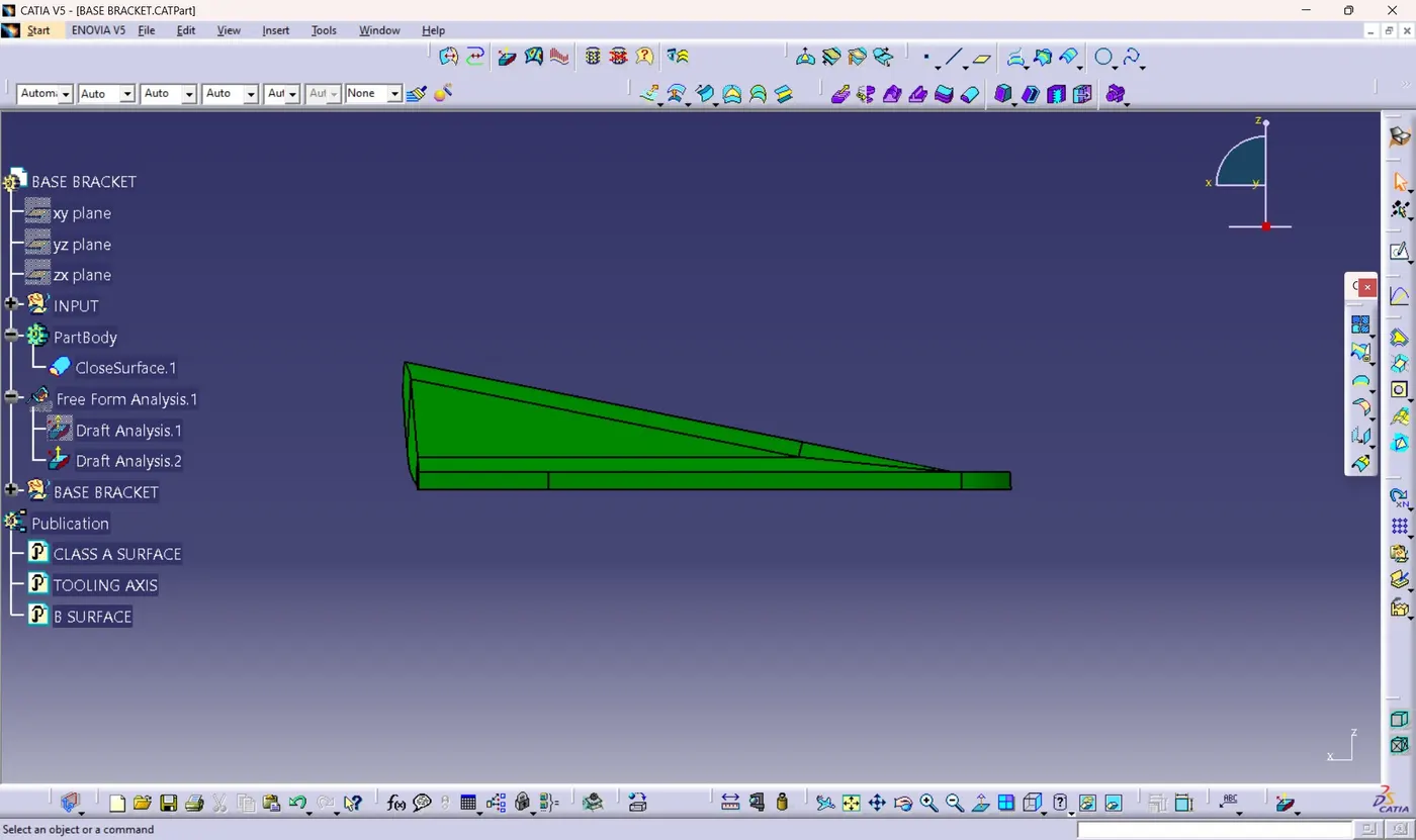
4) Top view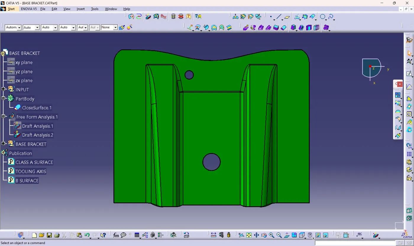
5) Bottom View