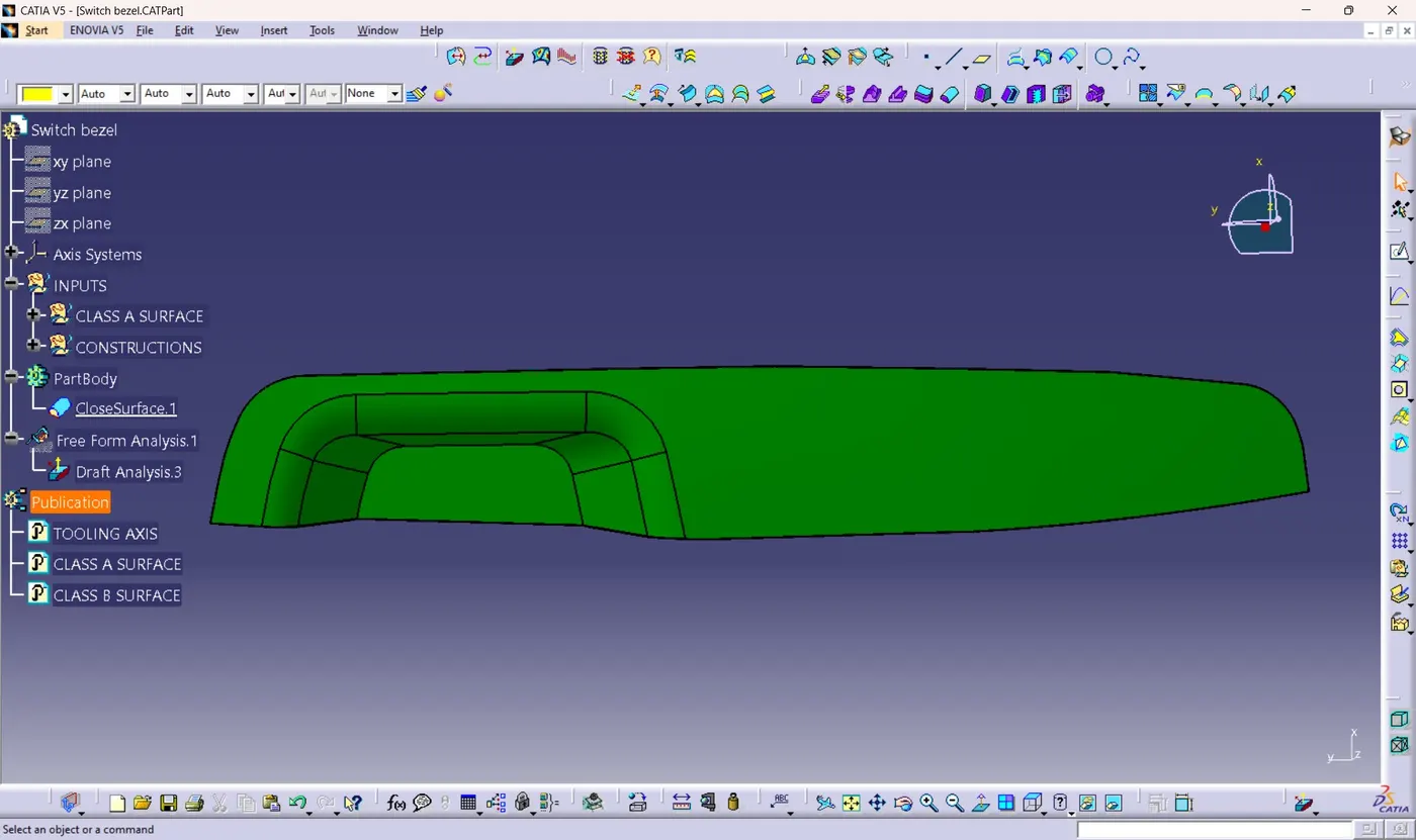
Week 9 - Challenge 2 - Switch Bezel Design
SWITCH BEZEL DESIGN
CREATION OF TOOLING AXIS
1) As the class A surface has a flat base and remaining faces are inclined to it, Extract the base surface and create a point on it with 0cm cordinates.
2) Create a line through that point as normal to surface as option.
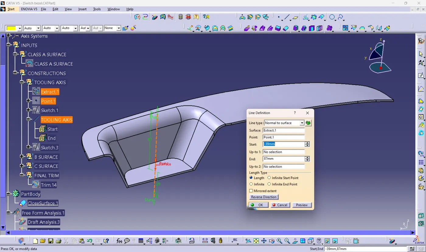
3) The line created can be named as "Tooling Axis"
Note : Tooling axis can also be created by using sketch method by extracting all side walls and creating bisecting line. But by that method I was not getting proper draft results. As a result taking opinion from online section mentor advised to do by Normal to surface method.
DRAFT ANALYSIS OF CLASS A SURFACE
1) From the analysis toolbar click on the Feature draft analysis.
2) From the Draft analysis toolbar select the compass tool.
3) Click and drag the compass by selecting on the red dot.
4) Align the z axis with the tooling axis direction.
5) After aligning perfectly with the tooling axis click on the Lock option.
6) After Locking click on the surface and it will appear in the desired colour as per the draft angle.
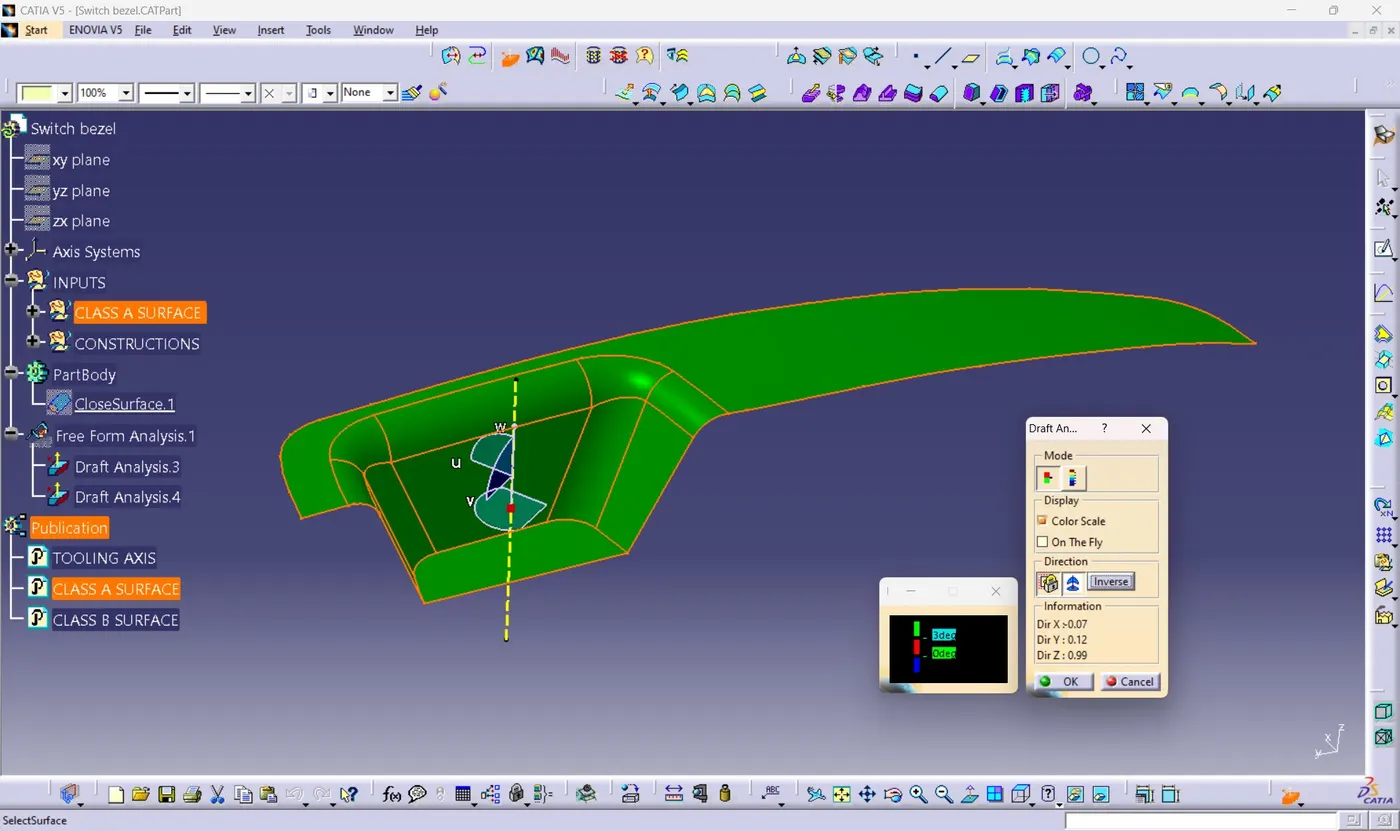
7) Here all the surfaces passes minimum draft angle of 3 Degree. Hence the Draft analysis is postive for class A surface.
DRAFT ANALYSIS OF FINAL COMPONENT
1) Repeat the steps done for class A surface Draft Analysis till selection of surface.
2) After locking the compass aligned with tooling direction, select on the component.
3) The component colour will be changed as per the draft angles colour codes.
4) The mininum draft angle provided is 3 degrees. 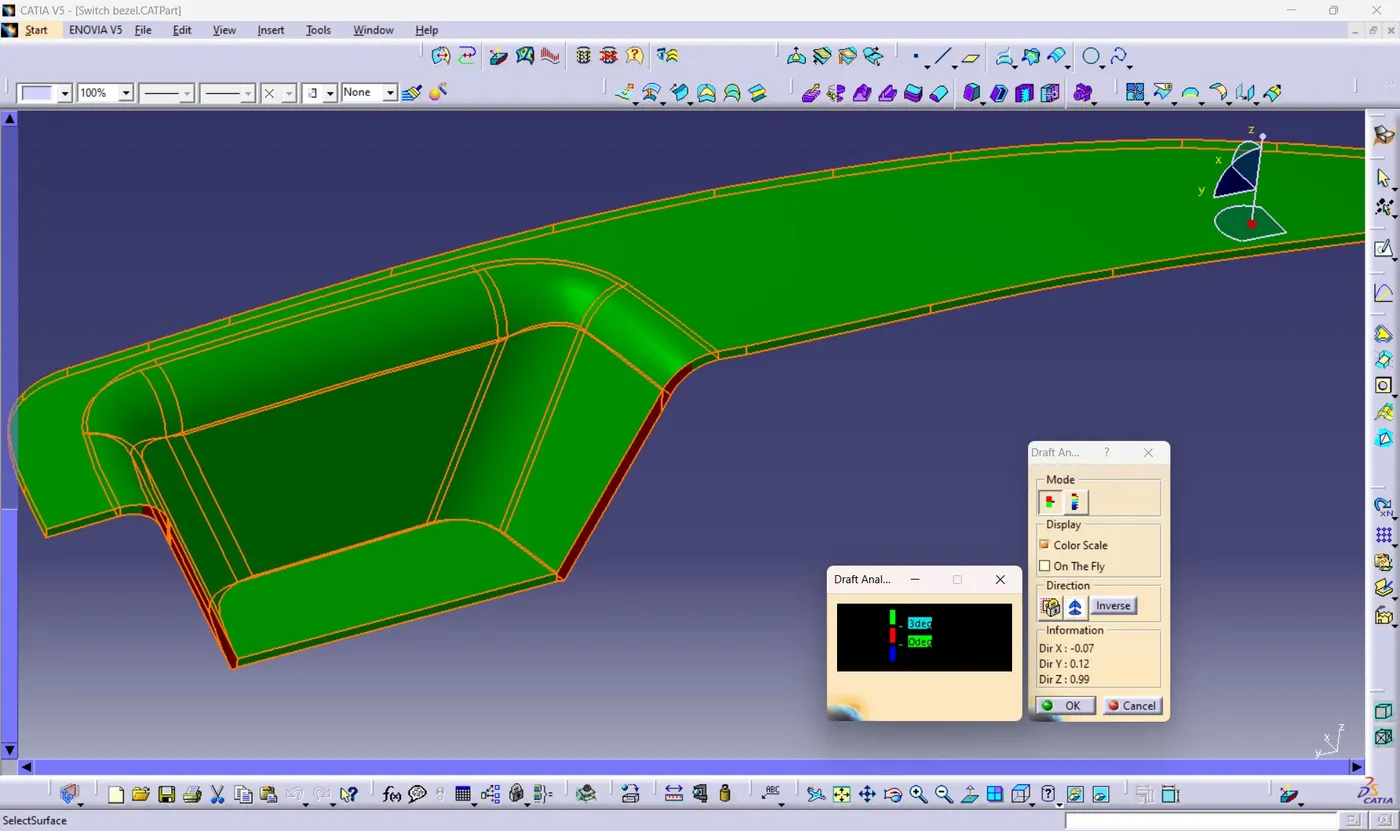
5) Here most of the areas passes draft analysis, but some areas failed which is shown in red colour.
6) For sorting out this issue click on " On the fly " option from draft table.
7) After clicking, drag the cursor to the red surfaces. moving all the way through surfaces it will show current angle of that surface with tooling axis. 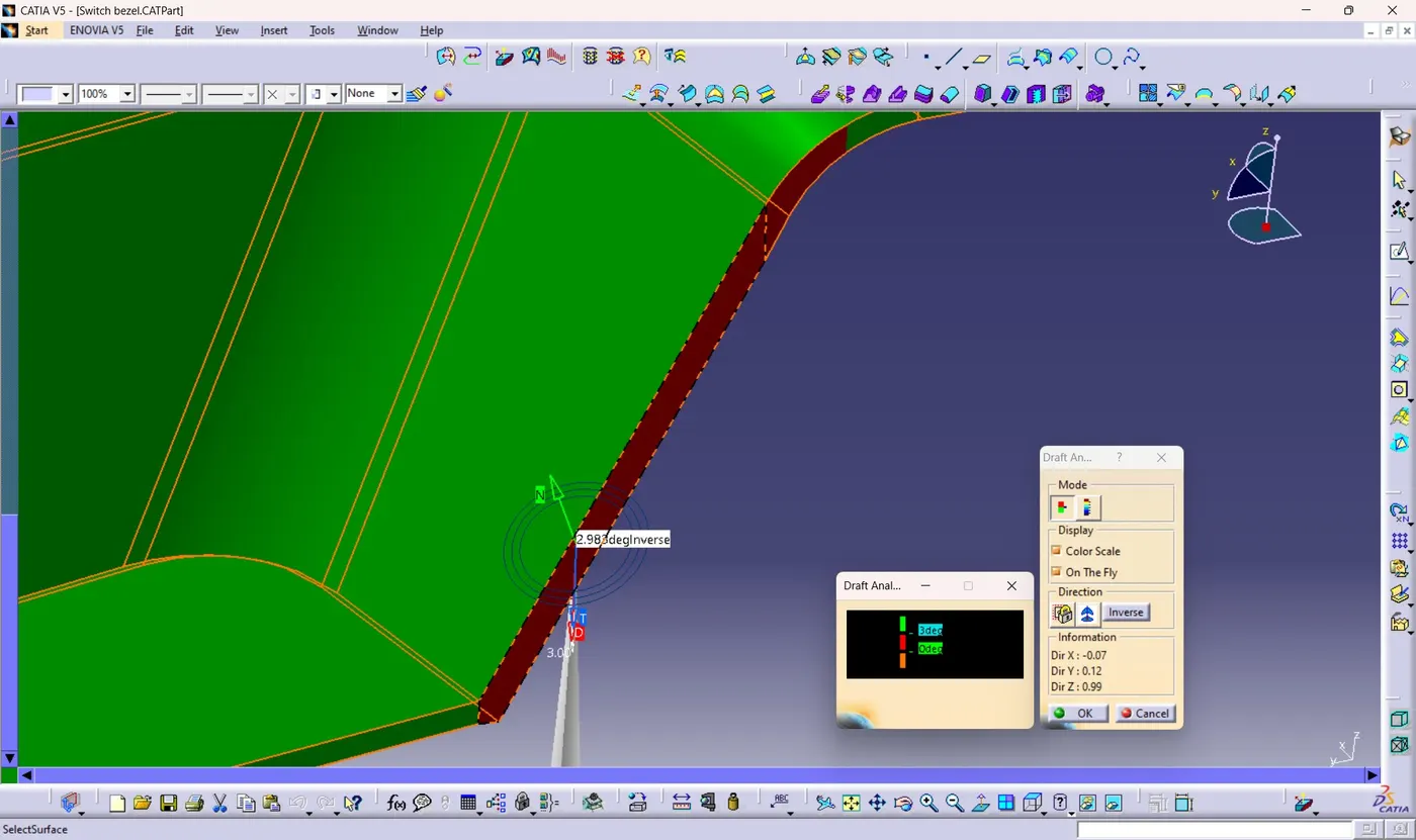
8) Here almost all red surfaces are making an angle of 2.9 degrees with tooling.
9) So we have to reduce the minimum draft angle from 3 degree to 2.9 degrees by double clicking on the 3deg from draft analysis colour code table.
10) changing to 2.9 degrees is a slight variation which is acceptable. 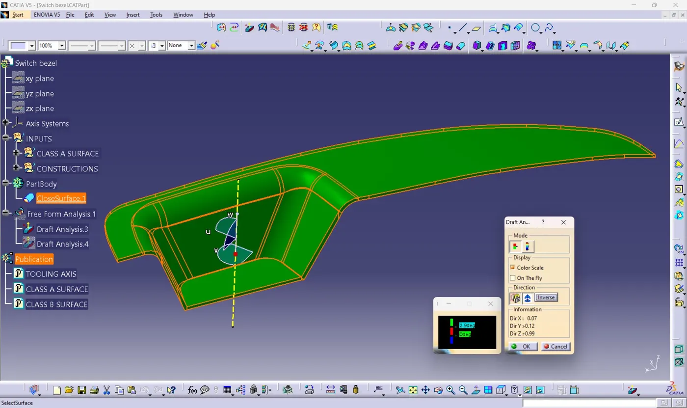
11) After changing the minimum draft angle to 2.9 degrees the final product clears the draft analysis and its ready move for production.
FINAL PRODUCT IN VARIOUS ORIENTATIONS
1) ISOMETRIC VIEW 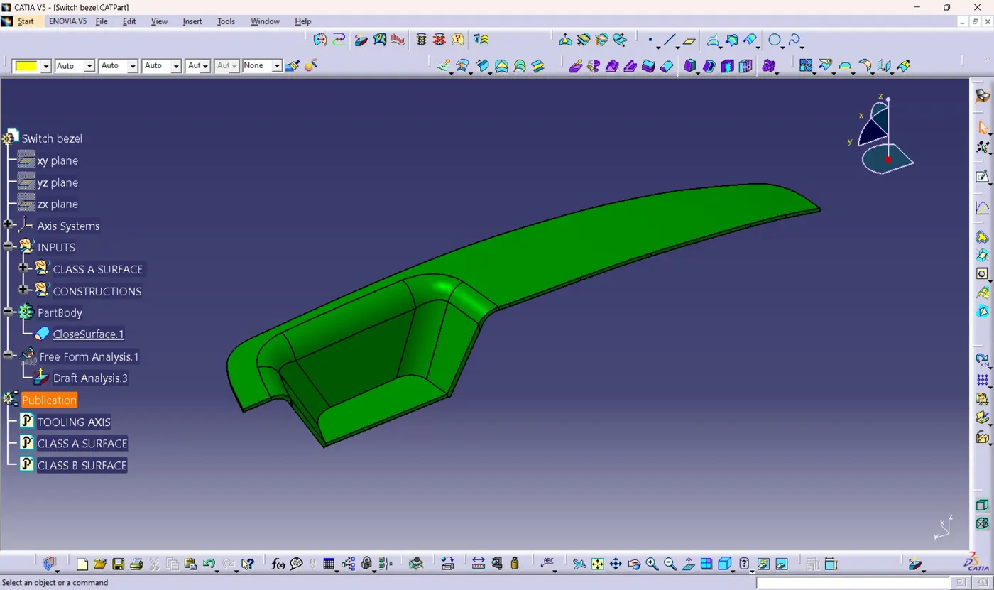
2) FRONT VIEW 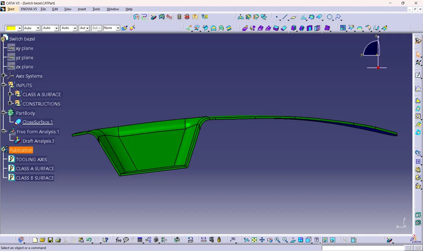
3) SIDE VIEW 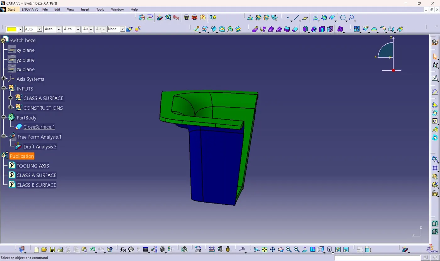
4) TOP VIEW