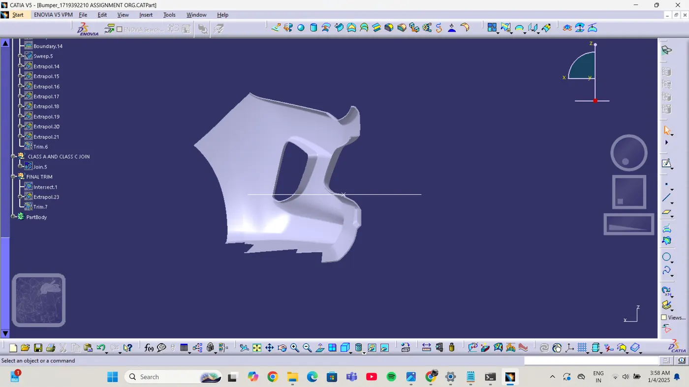
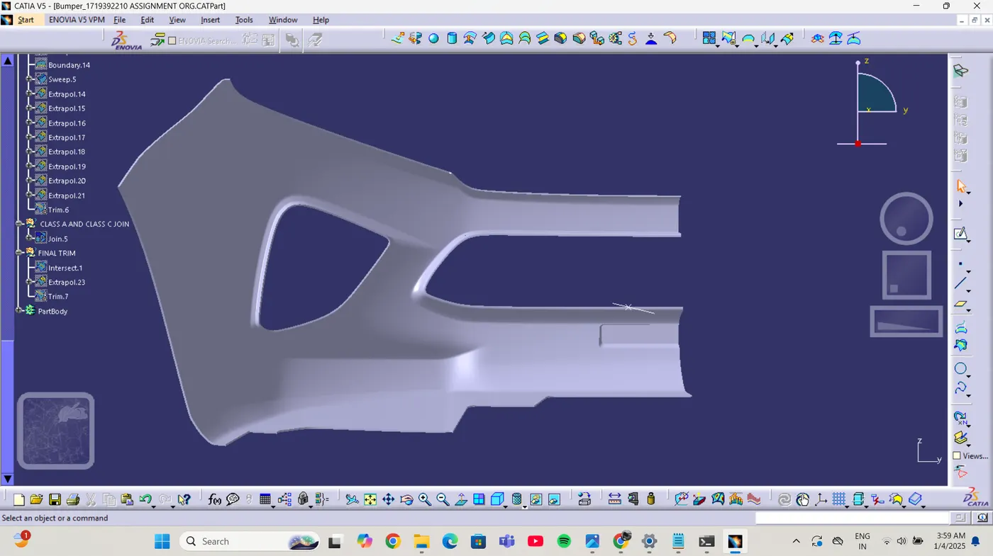
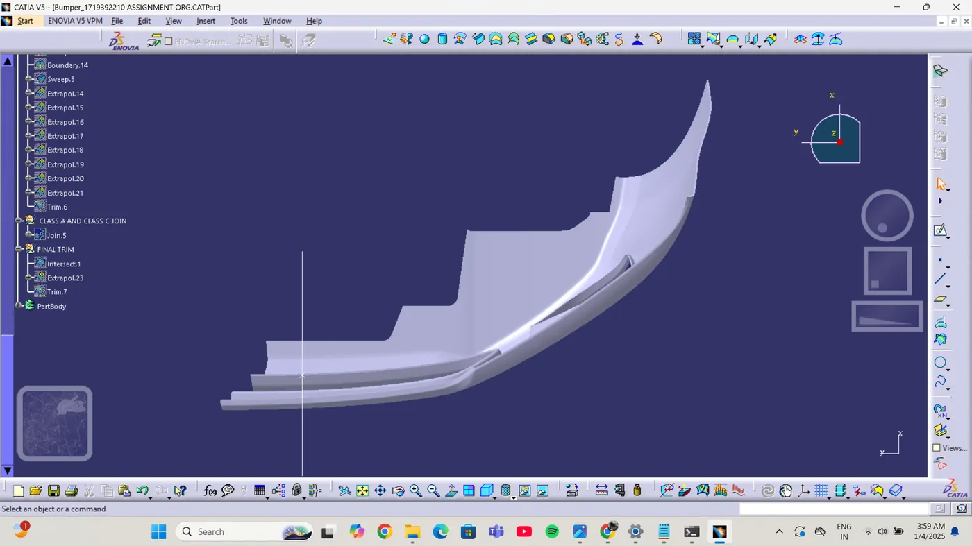
Week 9 - Challenge 3 - Bumper
DETAILED REPORT: TOOLING AXIS CREATION
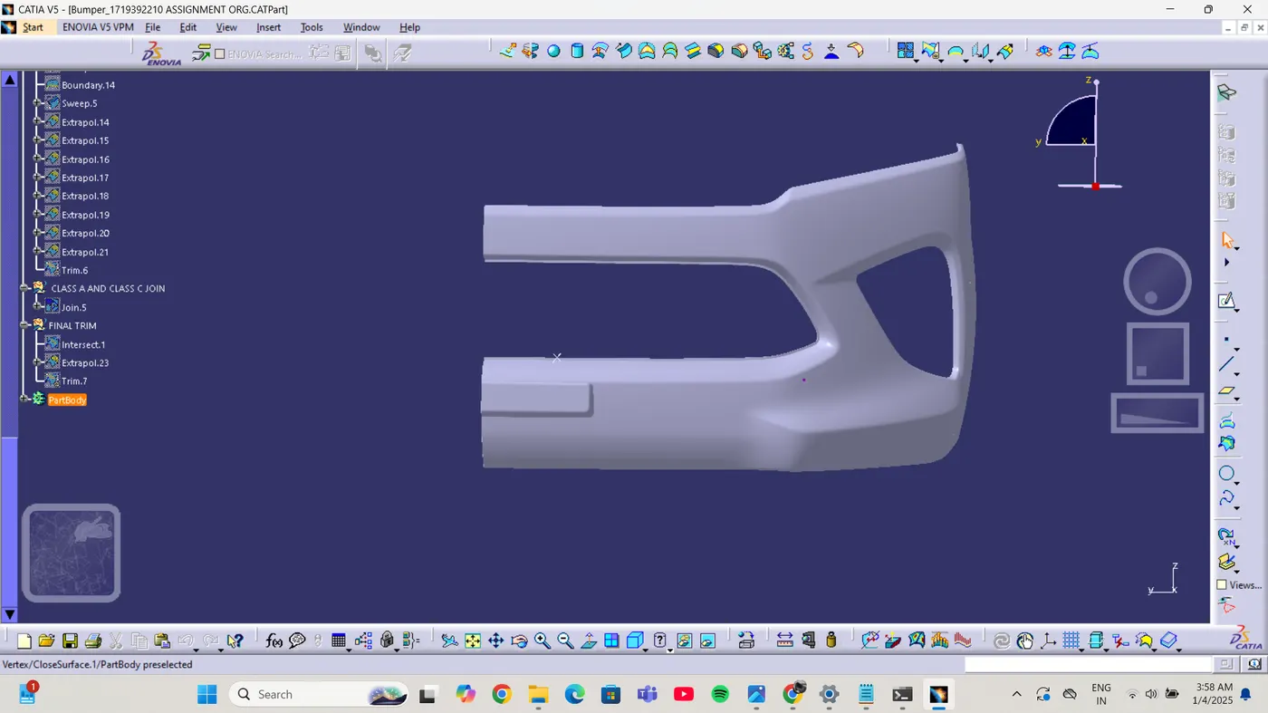
The tooling axis is a crucial element in surface modeling and is used as the reference direction for the manufacturing process, especially for performing draft analysis and ensuring that the part can be removed from a mold during production.
OBJECTIVE
The objective is to create a tooling axis for the given bumper design that aligns with the draft direction, ensuring the part is manufacturable.
STEPS IN CREATION OF THE TOOLING AXIS
1: Selection of reference geometry
the class A surface was provided as the reference geometry. a point on the surface where the draft and tooling directions would intersect.
2 Creation of point
A point was created on the class A surface at a strategic location to serve as the base of the tooling axis.
3 Analyses of part oreintation
the parts orientation relative to the principal planes was reviewed to identify the best possible planes the direction was chosen to minimize undercuts and ensure ease of manufacturing.
4 Line creation
A line was created through the selected point in the tooling direction line was defined as passing through point and aligned with the z axis.
5 draft analysis validation
The created tooling axis was validated using draft analysis to ensure it provided adequate clarity for part removal.
CONCLUSION
tooling axis was successfully created by analyzing the class A surface , selecting a strategic reference point , and creating a line along the z axis this tooling axis was validated with draft analysis to ensure manufacturability , and the results confirmed its sustainability for the bumper design.
DETAILED REPORT: DRAFT DIRECTION AND DRAFT ANALYSIS
Draft analysis is a crucial step to ensure manufacturability by verifying the draft angle of the part relative to that the part can be easily ejected from the mold withut damage
Steps involved in draft analysis
1 Setting the tooling axis as draft direction
tooling axis created earlier was selected as the draft direction in the draft analysis tool
2 analyzing the draft angle
when in the creation of c surface, the draft angle was set of 3 degree as the minimum requirement
3 interpretations of colour codes
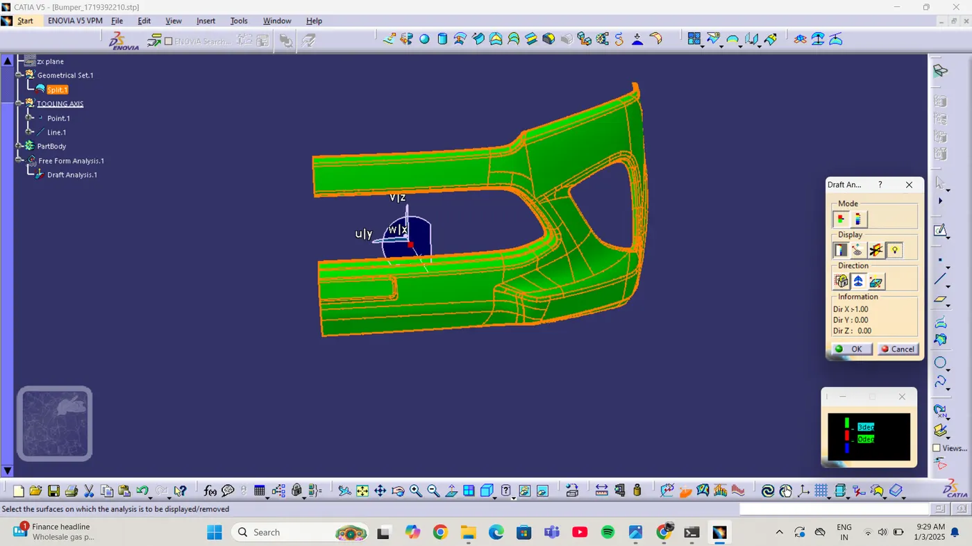
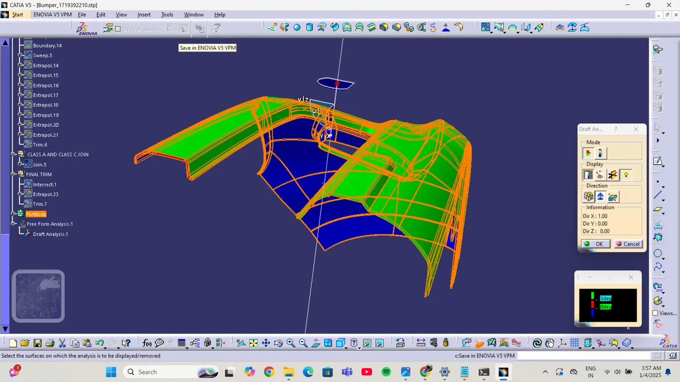
green : Surface with a draft angle =3 degree
red : surface with a draft angle less than 3
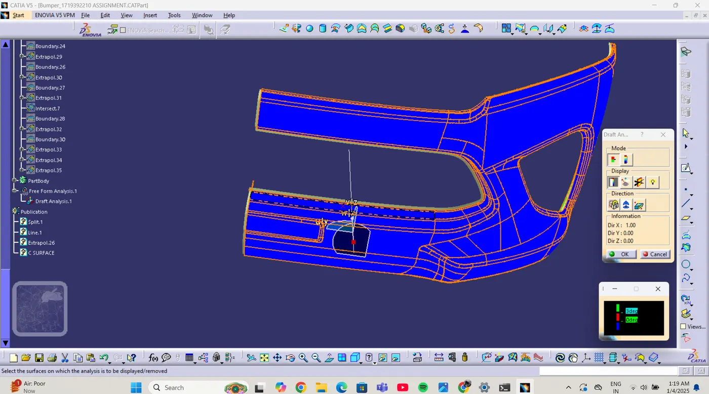
blue : surface perpendicular to the tooling direction
4 results
the analysis indicated that all part surfaces had the required 3-degree draft, as shown by the dominant green in the analysis.
CONCLUSION
The part met the 3-degree draft requirements across all surfaces , making it suitable for manufacturing