Week 9 - Challenge 3 - Bumper
1.TOOLING AXIS
2.DRAFT ANALYSIS
2.1 CLASS A SURFACE
2.2 FINAL COMPONENT
3. CLASS B & C SURFACE
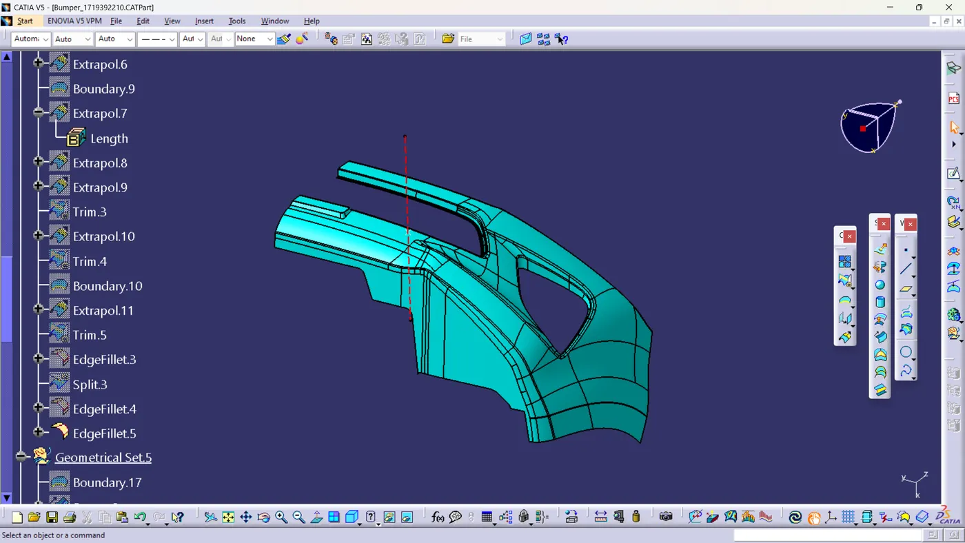
TREE STURCTURE & Publications
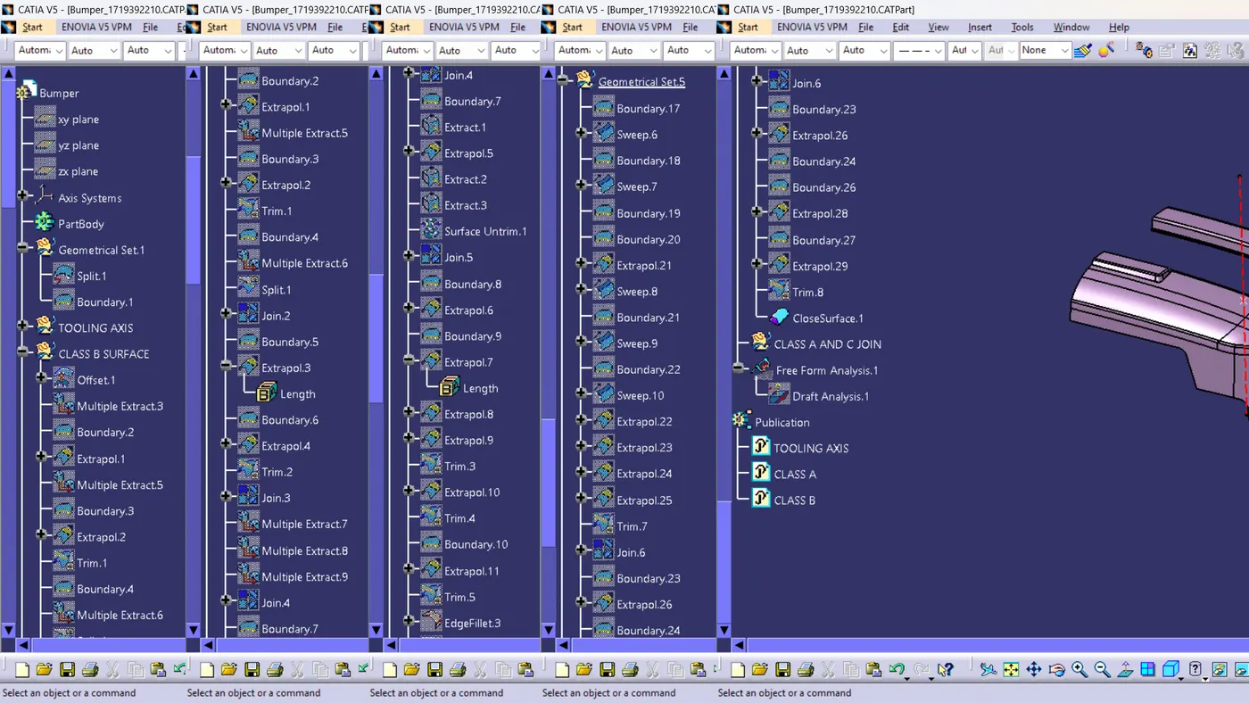
REPORT.
DRAFT ANALYSIS
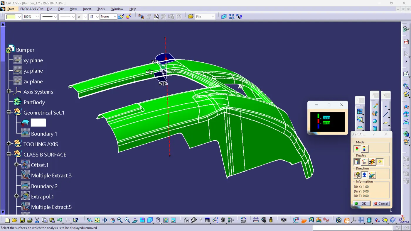
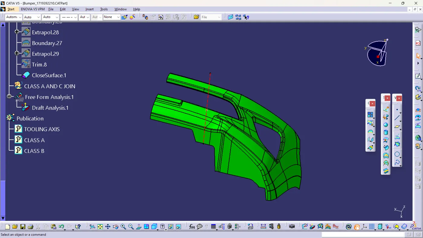
The bumper design was evaluated using a draft analysis, with a component thickness of 3mm, ensuring structural integrity. The analysis revealed the following draft angles: green areas represent a positive draft of 3 degrees, indicating optimal manufacturability, blue areas represent a neutral draft of 0 degrees, which may require further optimization, and blue areas also indicate a negative draft of -3 degrees, potentially posing issues during mold release. To enhance manufacturability, areas with 0 or negative drafts should be adjusted to achieve a positive angle where possible, minimizing the risk of defects during production.
TOOLING AXIS
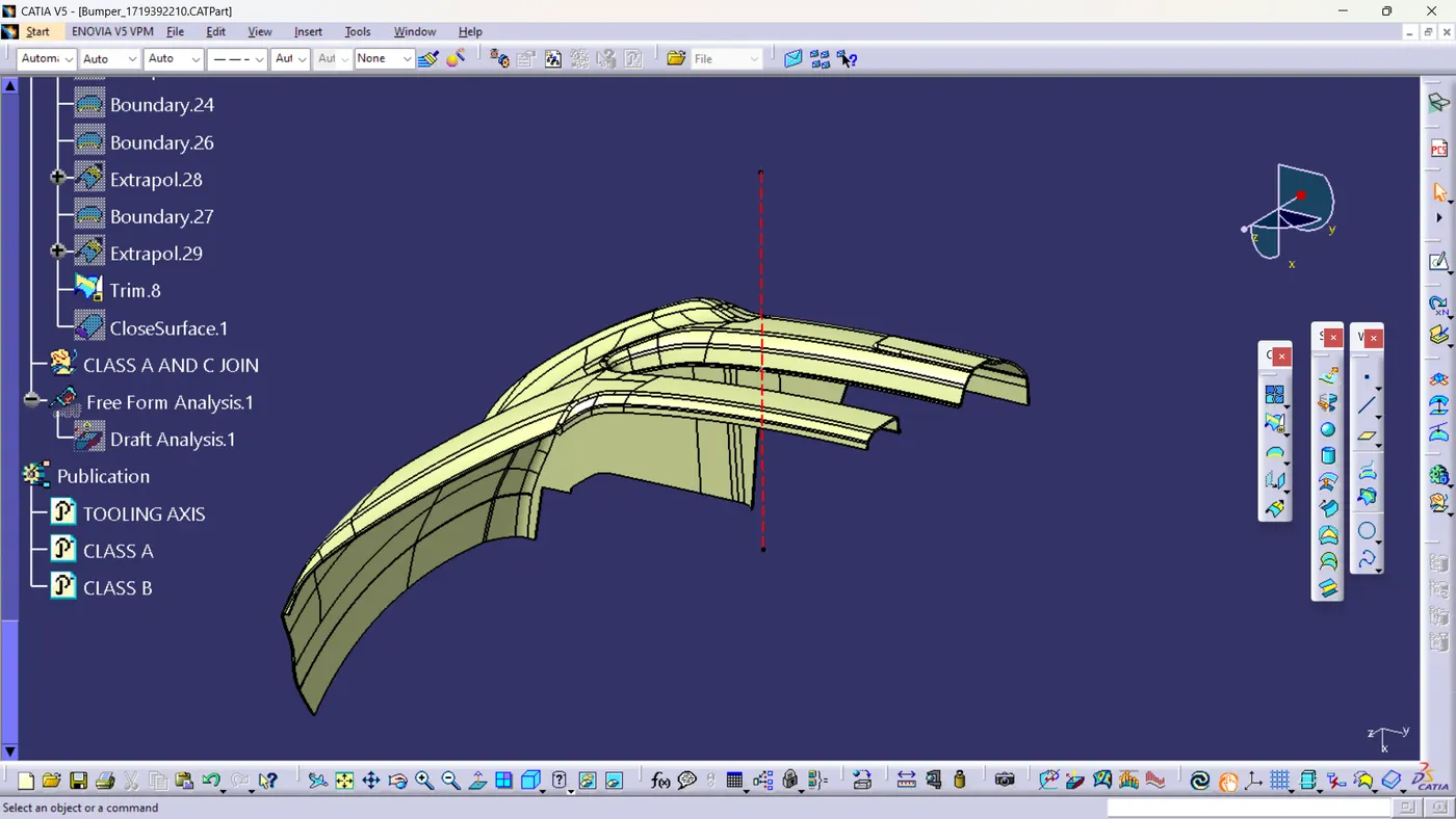
The tooling axis for the bumper was created by selecting the most visible area to ensure smooth mold release, while considering both the die and cavity making process. The grill area surface edge was strategically used to create a reference point, essential for defining the tooling axis. Using the point-and-direction line method, the axis was aligned to facilitate optimal draft angles. In this model, the tooling axis was defined as a red-colored construction line .This approach minimizes defects, enhances manufacturability, and ensures efficient part removal during plastic injection molding.