Week 10 - Challenge 1- Attachment Feature Creation (Ribs & Screw Boss)
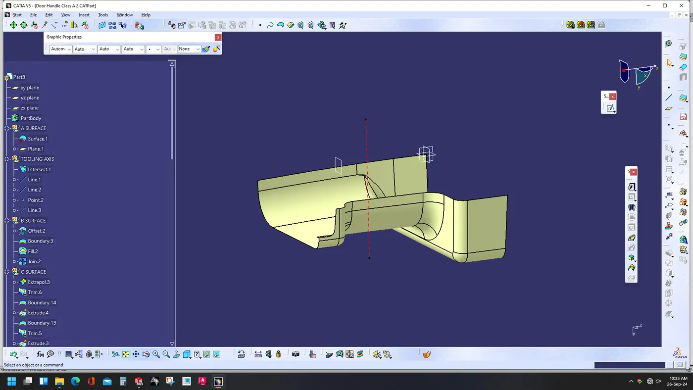
1.Tooling Axis
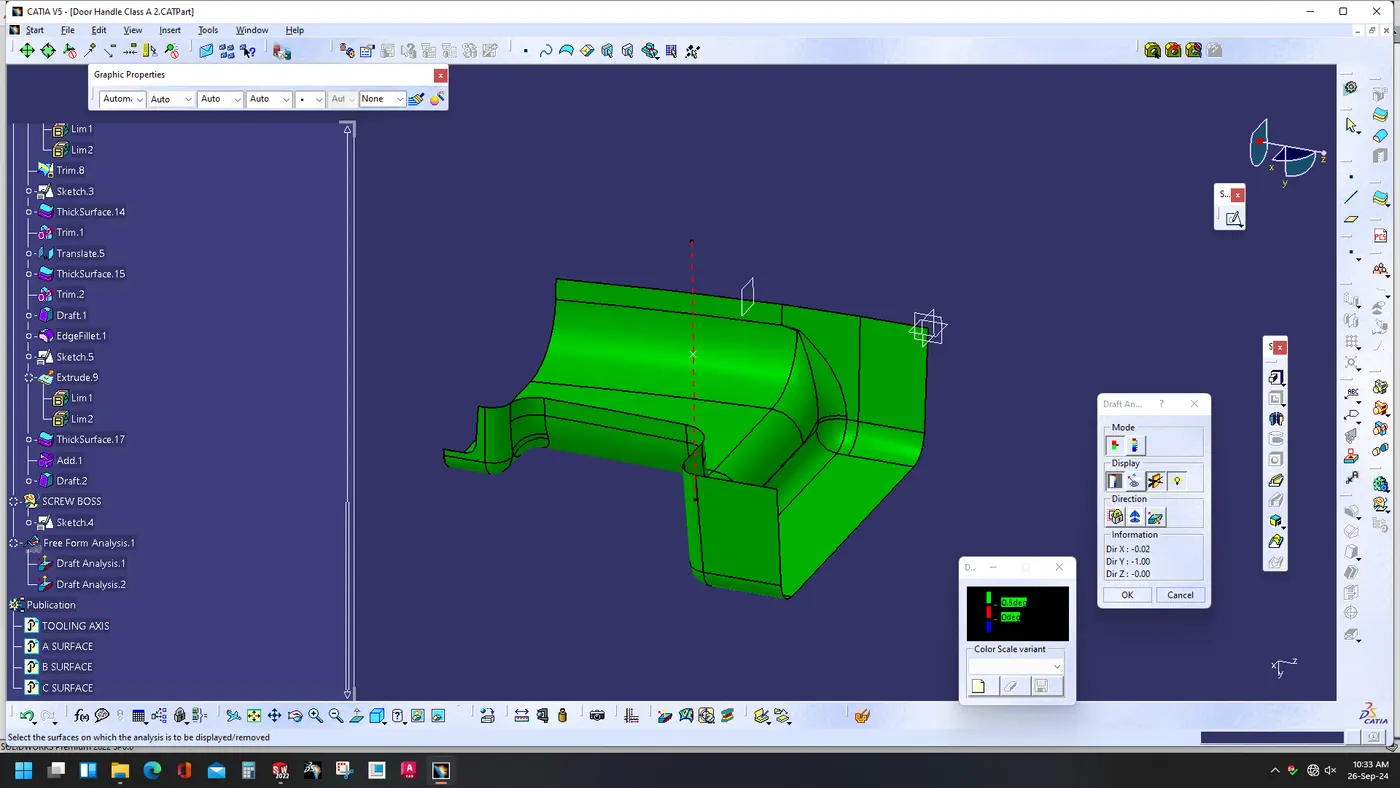
2.Draft Analysis
2.1 Initial Analysis.
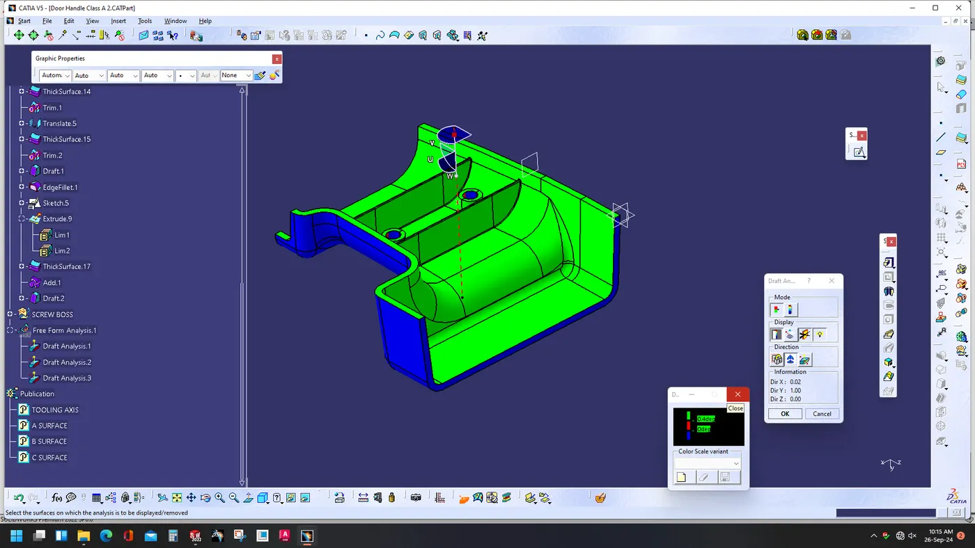
2.2 Final Analysis.
3.Class
B & C surfaces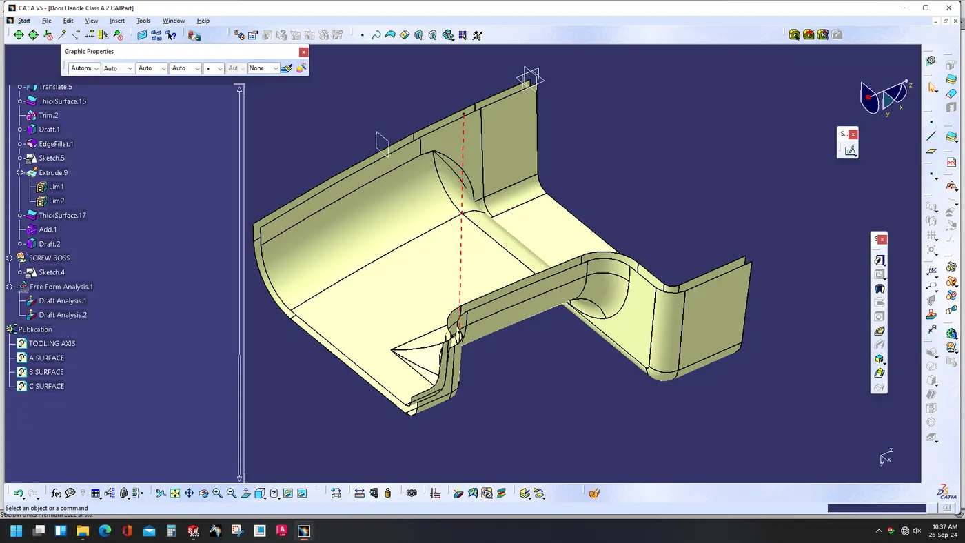
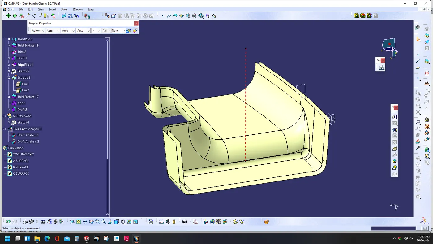
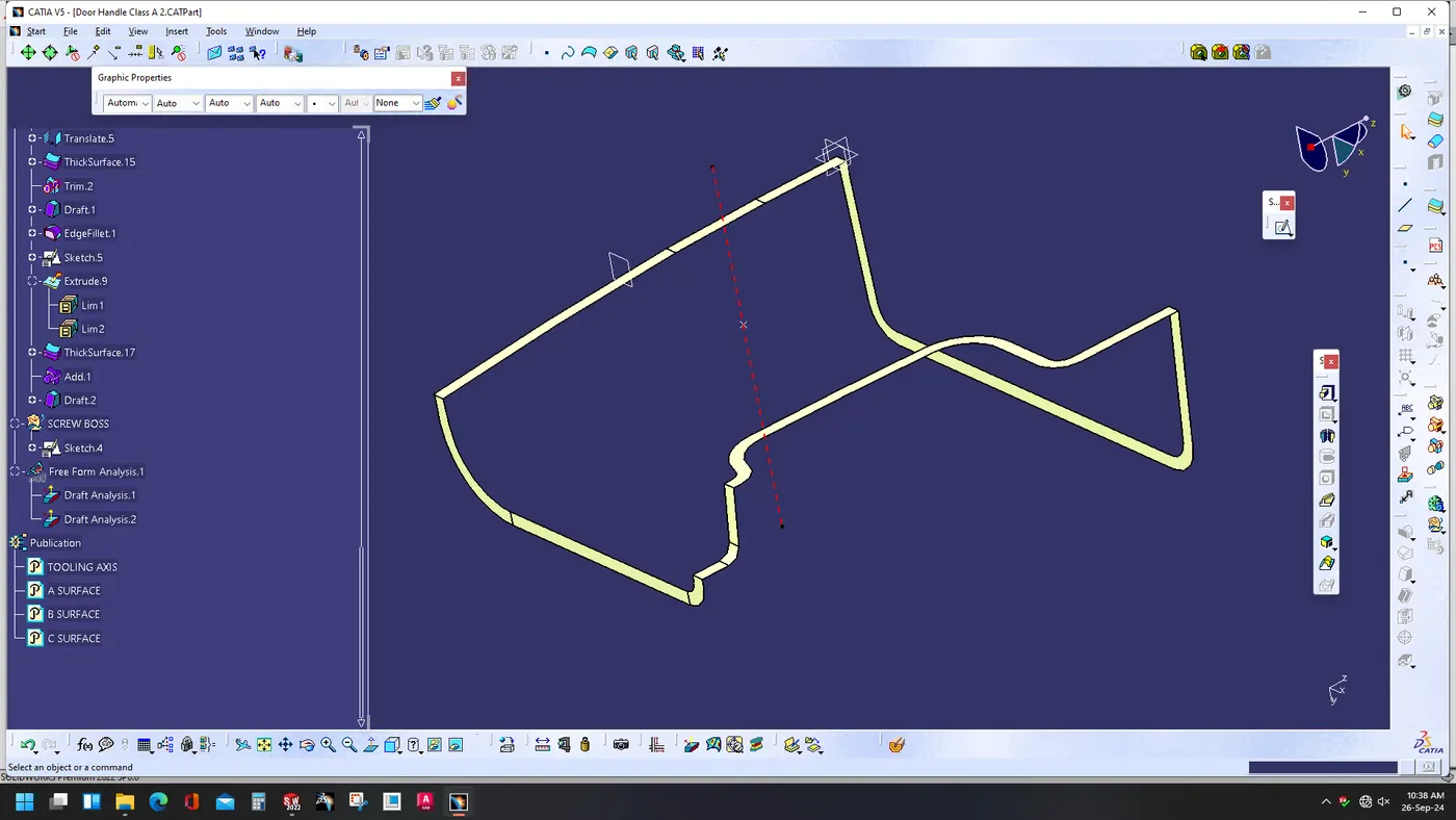
4.Tree Structures & published elements.
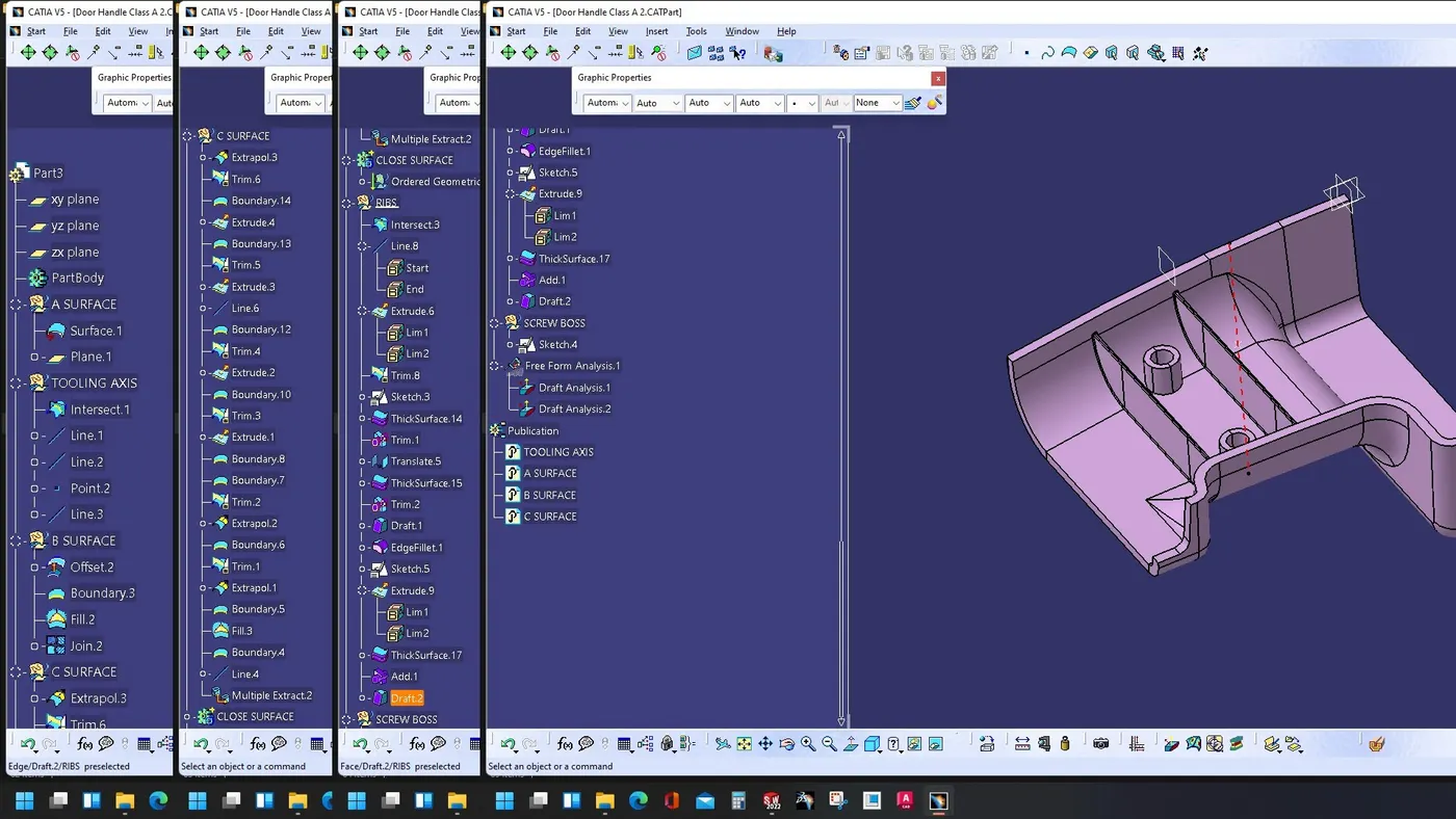
5. Multiple Views
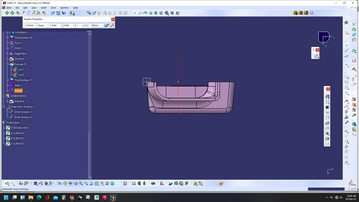
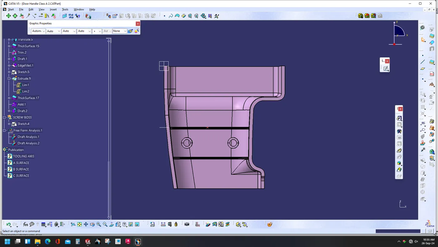
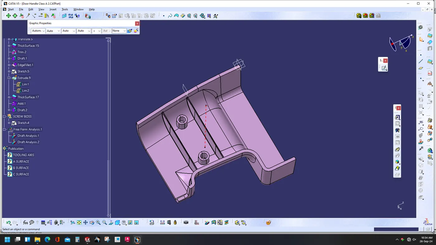
6.Reports
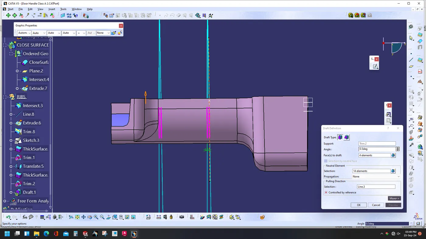
Component: Drill Machine Handle
Wall Thickness: 2.5 mm
Draft Angle: 0.5 degrees (walls of boss)
Height-to-Diameter Ratio: 3:1 (for screw boss)
Maximum Radii: 0.25 mm
Ribs:
The ribs are designed with a 0.5-degree draft angle as well, ensuring smooth ejection from the mold and reducing the risk of warping. The rib thickness is about 60% of the nominal wall thickness, which helps prevent sink marks while providing adequate strength. The edges of the ribs are rounded with a 0.25 mm radius to avoid stress points and enhance durability. This design ensures both functional strength and manufacturability.
Screw Boss:
The screw boss is designed with a 0.5-degree draft angle to facilitate easy ejection from the mold. The wall thickness is kept at 40% of the nominal wall thickness (approximately 1 mm), ensuring optimal material flow and avoiding sink marks. The height-to-diameter ratio follows the standard 3:1 to provide adequate structural integrity without compromising the moldability. A 0.25 mm radius is applied at the base to prevent stress concentrations and ensure smooth transitions during the molding process.
Tooling Axis:
The tooling axis for the drill machine handle was created by Using bisecting line method, the axis was aligned to optimize draft angles and facilitate easy ejection. The screw boss and ribs were considered to maintain uniformity during part removal. A red-colored construction line represents the tooling axis in this model. This approach minimizes defects, enhances manufacturability, and ensures efficient part removal.