Week 9 - Challenge 3 - Bumper
REPORT ON BUMPER DESIGN AND DRAFT ANALYSIS
OBJECTIVE:
The aim of Challenge to Create Bumper by taking input Class A surface and Perform Draft Analysis on the same.
TOOLING AXIS:
Tooling axis is much more important in Designing Plastic components to analyse the Draft angle which is used to define the Direction in which mould core or cavity opens. The following steps used to create Tooling Axis.
- Extract the surface to create Point for the Position of Tooling Axis.
- Created Centre Point by using Point on Surface method at middle of that surface.
- Created Line by using Point-Direction method perpendicular to surface.
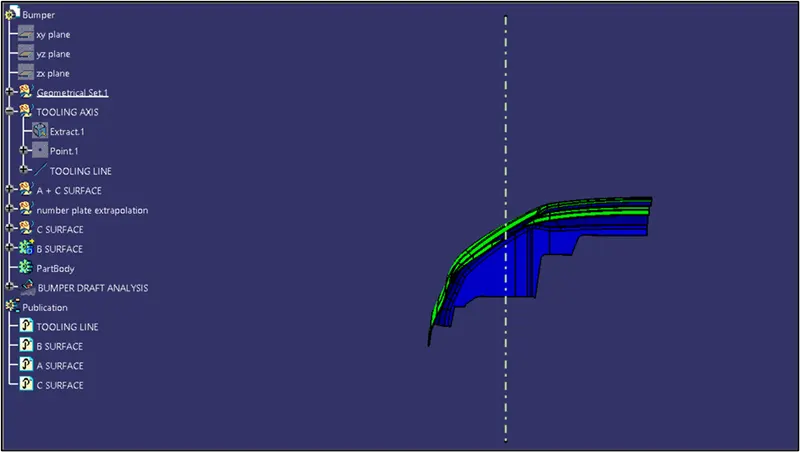
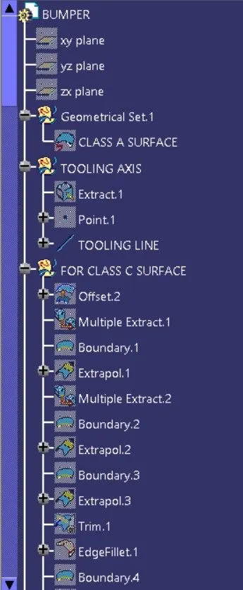
The above image shows the example of Tooling axis (can see in Feature Manager Tree)
DRAFT ANALYSIS:
Draft analysis is done after determining the tooling axis, draft analysis is used to check whether the minimum draft (3 degrees) is maintained or not. Compass is used to define the draft direction.
- The draft analysis is to identify the body is in proper draft angles or not.
- The normal draft angle of the body is 3 deg.
The draft angle allows the part to remove or eject from the mould.
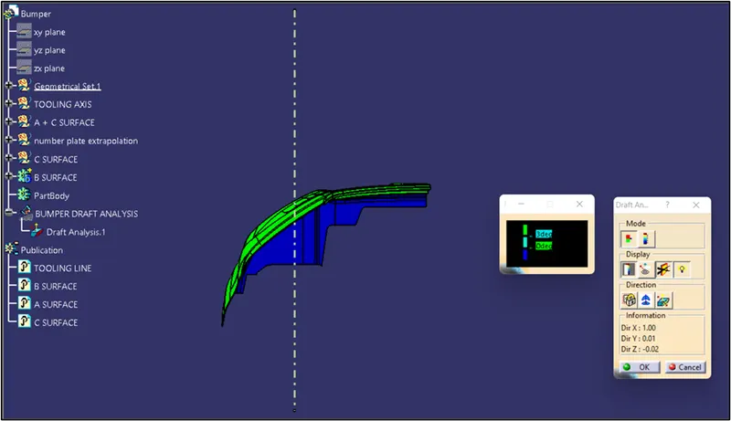
The above image shows the Final Plastic Component Draft Analysis.
IMAGES:
FRONT VIEW
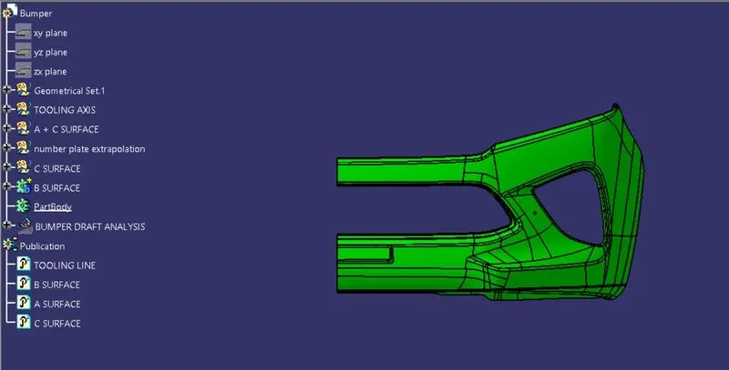
SIDE VIEW
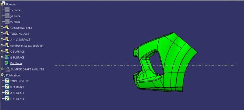
TOP VIEW
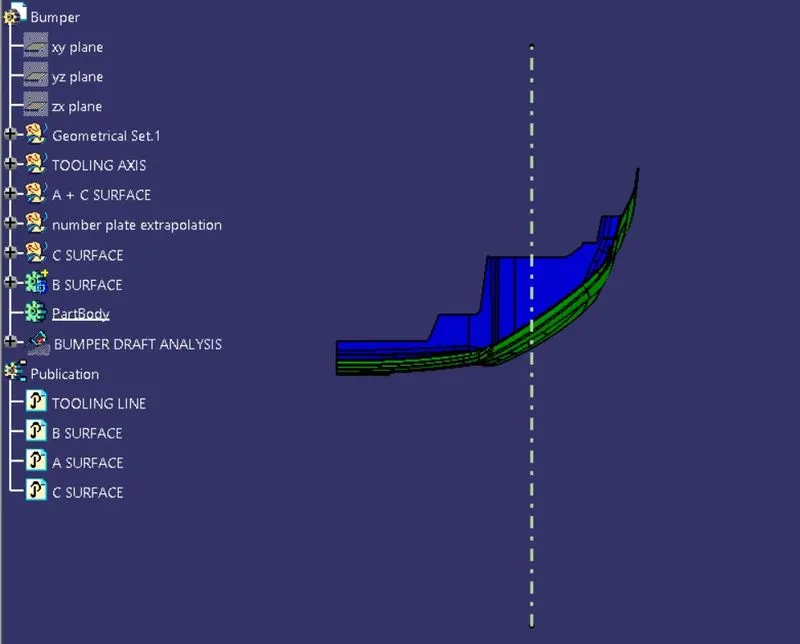
ISOMETRIC VIEW
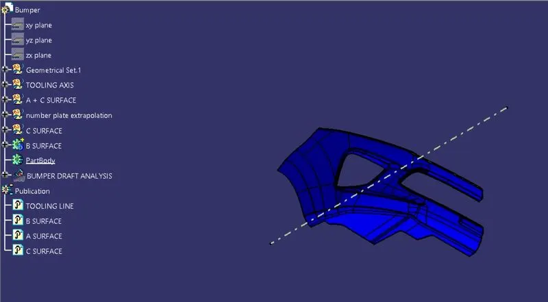
COLOR VARIATION IMAGE
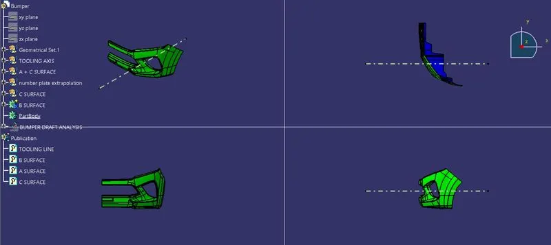
FEATURE MANGER TREES:
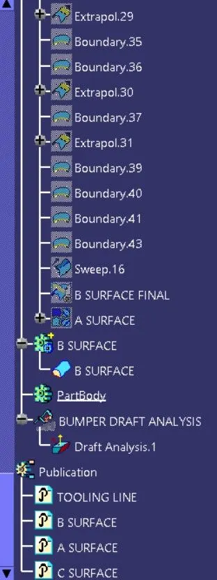
TREE_1
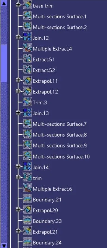
TREE_2
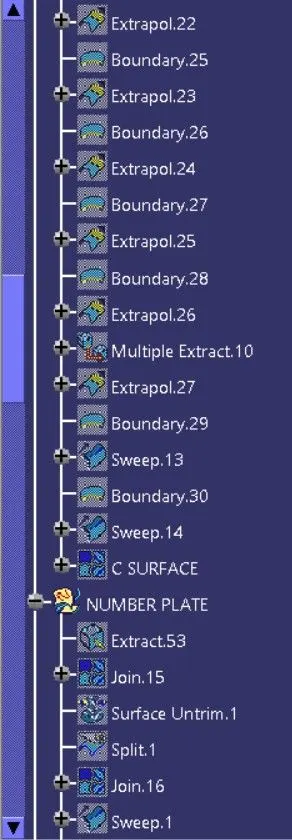
TREE_3
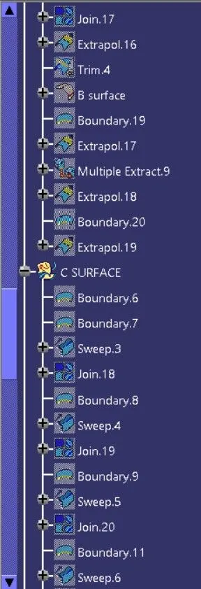
TREE_4
TREE_5
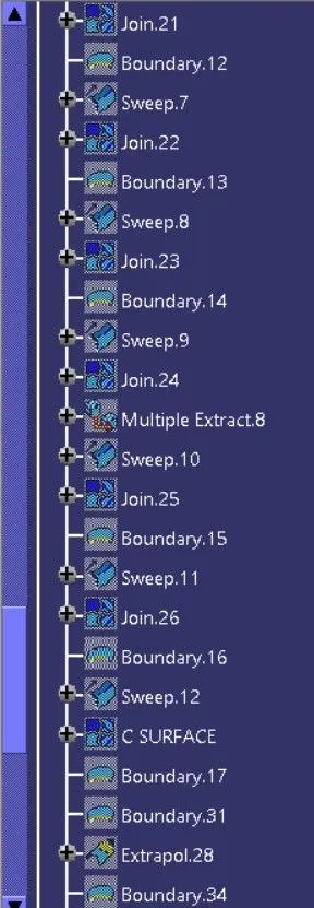
TREE_6