Week 9 - Challenge 3 - Bumper
BUMPER DESIGN
Objective:
To create a bumper component through a given class A surface and perform Draft Analysis on the final plastic component.
Introduction:
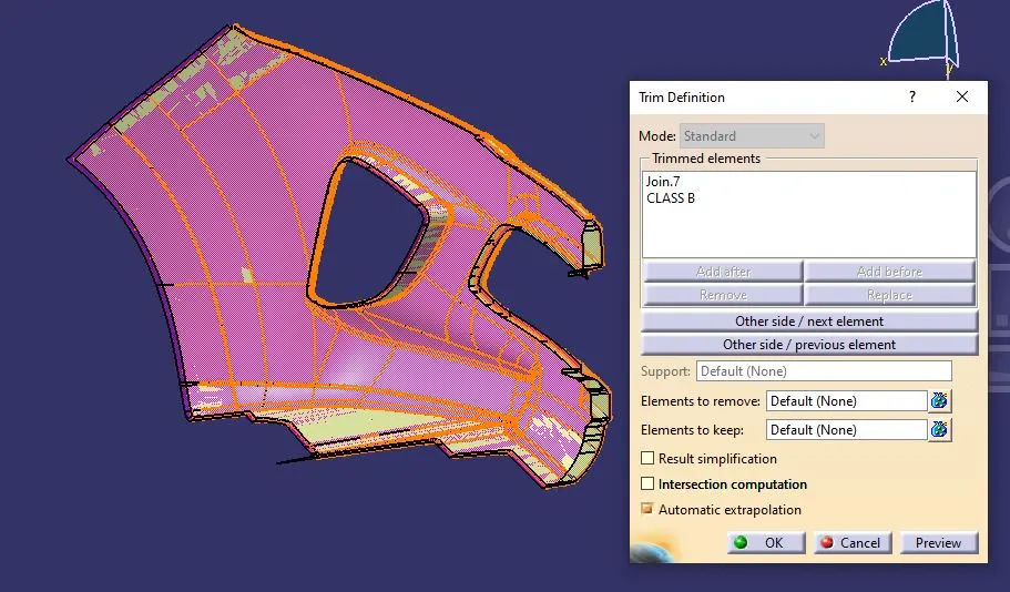
In this project we are designing a bumper component using given class A surface. The approach includes creation of class B surface keeping 3 mm thickness in mind for complete component. The design also included class C creation from the given parent surface.
Class A Surface:
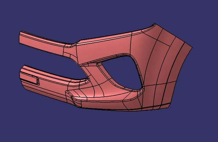
The given input surface is considered as Class A surface. Before creating a tooling axis, we have to check the connectivity of the surface and ensure there is no gap between the surfaces.
Connectivity Checking:
Tooling Axis:
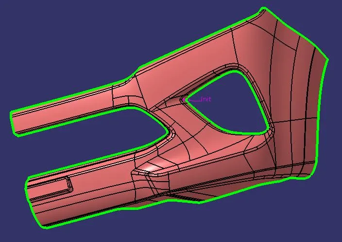
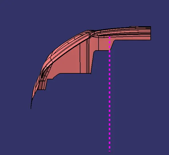
The direction in which the mold would open and close is called tooling axis. While creating the tooling axis give the tooling axis on a flat length surface or the surface which have a hole on it.
Create a point on the surface where we are going to create the dummy tooling axis and using line command create an axis. If there is a circle or flat length surface which is recommended. In this model we have to create a bisecting line by using two dummy tooling axis X and Y direction.
Draft Analysis:
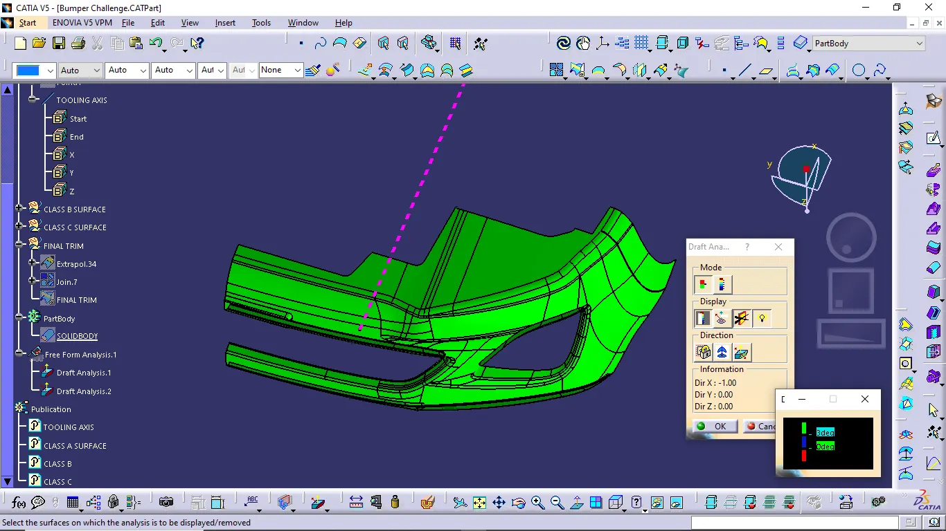
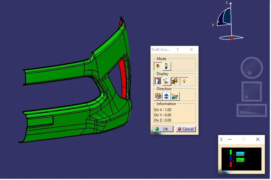
The draft analysis technique is used to analyze whether our part model created in CAD is manufacturable based on the draft condition applied. Here the part should get easily removed from the panel dies or mold. No parts can be ejected from the tool if it is having 90° profile from its base surface. A small draft angle is provided to each and every area of the component in order to get easy removal of the component from the tool. Here we are providing a direction in which components from the tool. In other word it also lets us know whether the model is having a draft angle and how much is the draft angle from the tool direction.
Class B Surface:
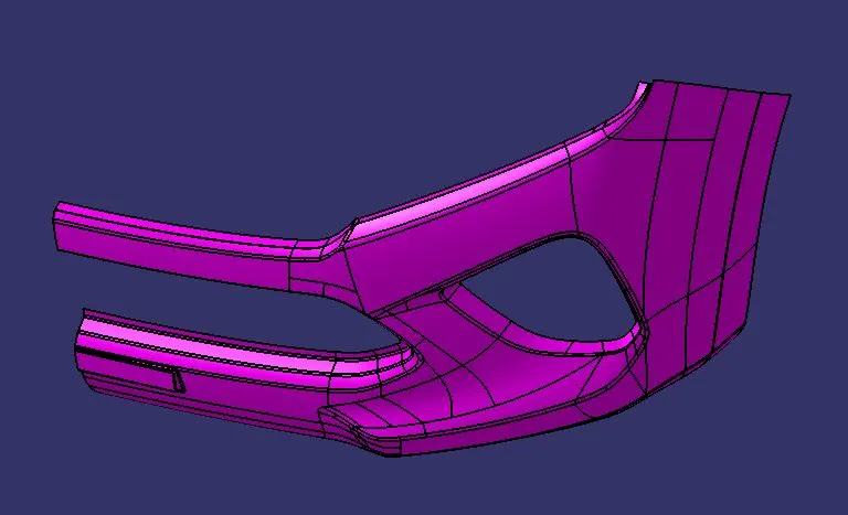
Class B surface is an offset surface to create a closed volume. To create a B surface, we have to offset the input surface in downward direction about 3 mm thickness. The offset surface is called Class B surface.
Class C surface:
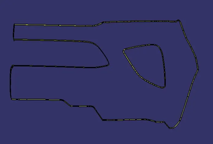
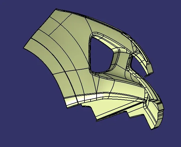
Class C surface is the surface which connect the class A and B surface together is known as Class C surface. It is created using sweep command. Boundary of the Class A surface is swept along the tooling direction.
Class A and C Join:
Final Trim:
Final Closed Surface:
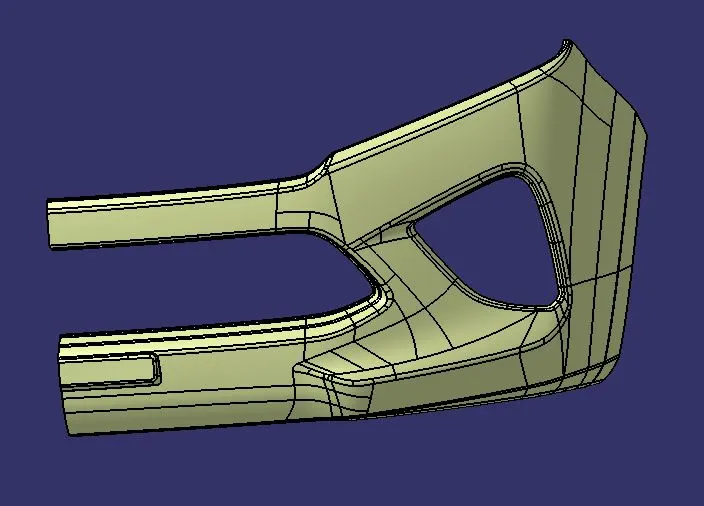
Solid Body Conversion:
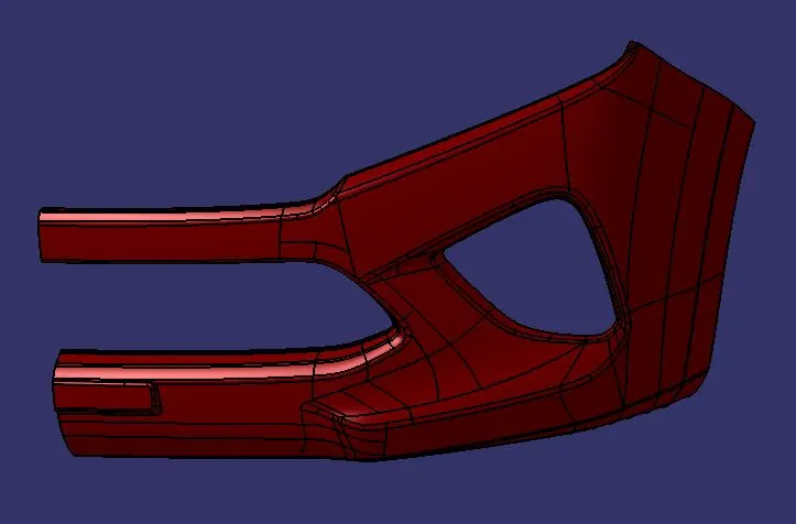
Orientations:
Front View:
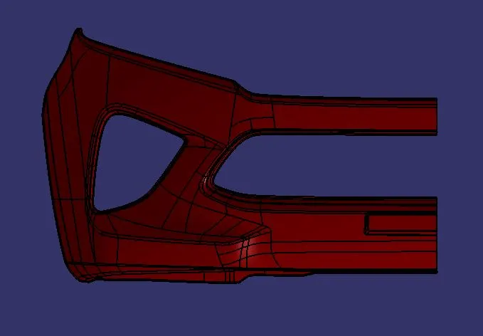
Right View:
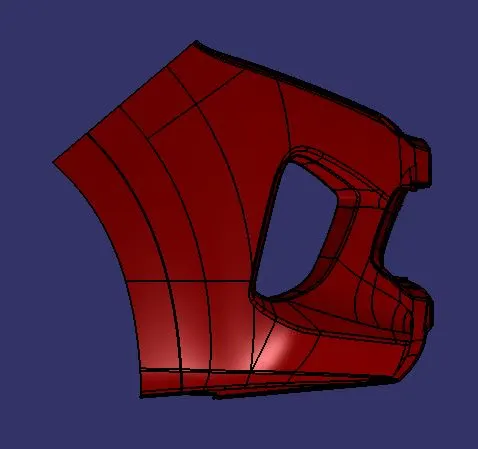
Top View:
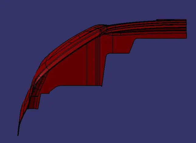
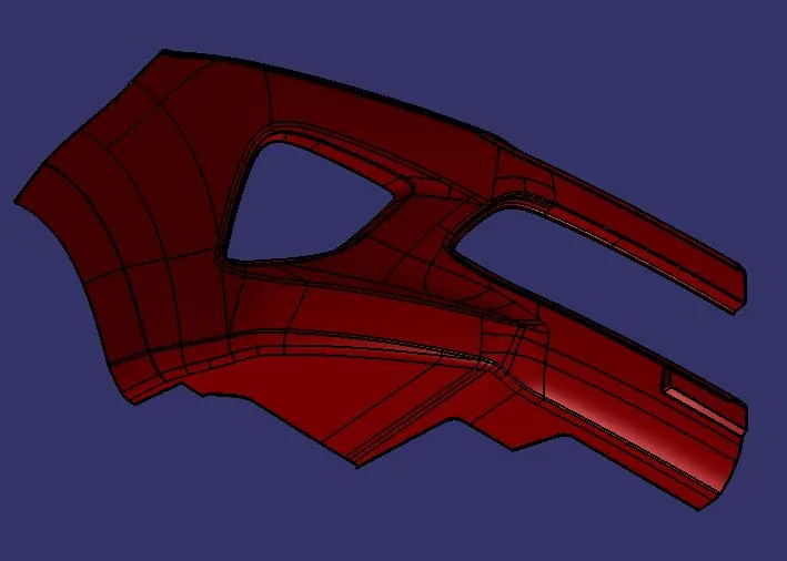
Isometric View:
Draft Analysis on Final Part:
Conclusion:
Thus, the bumper was created through given input surface and draft analysis performed on the final plastic component.