Week 10 - Challenge 3 - Door Trim Lower with Engineering Features
AIM:-
Create the Door Trim Lower Plastic component through the given Class-A surface. To begin with, the tooling axis for the given Class-A Surface should be created meeting the requirements of the draft angle and at the end perform the Draft analysis on the model.
Create the Heat Stakes and the locators as per design rules.
OBJECTIVE:-
1. Create a Tooling Axis on the given Class A-Surface.
2. Then create Class B-Surface and Class C-Surface to form a solid body.
3. Then create Heat stakes and Locators on that Solid body and do draft analysis.
SAMPLE DESIGN GIVEN:-
TOOLING AXIS:-
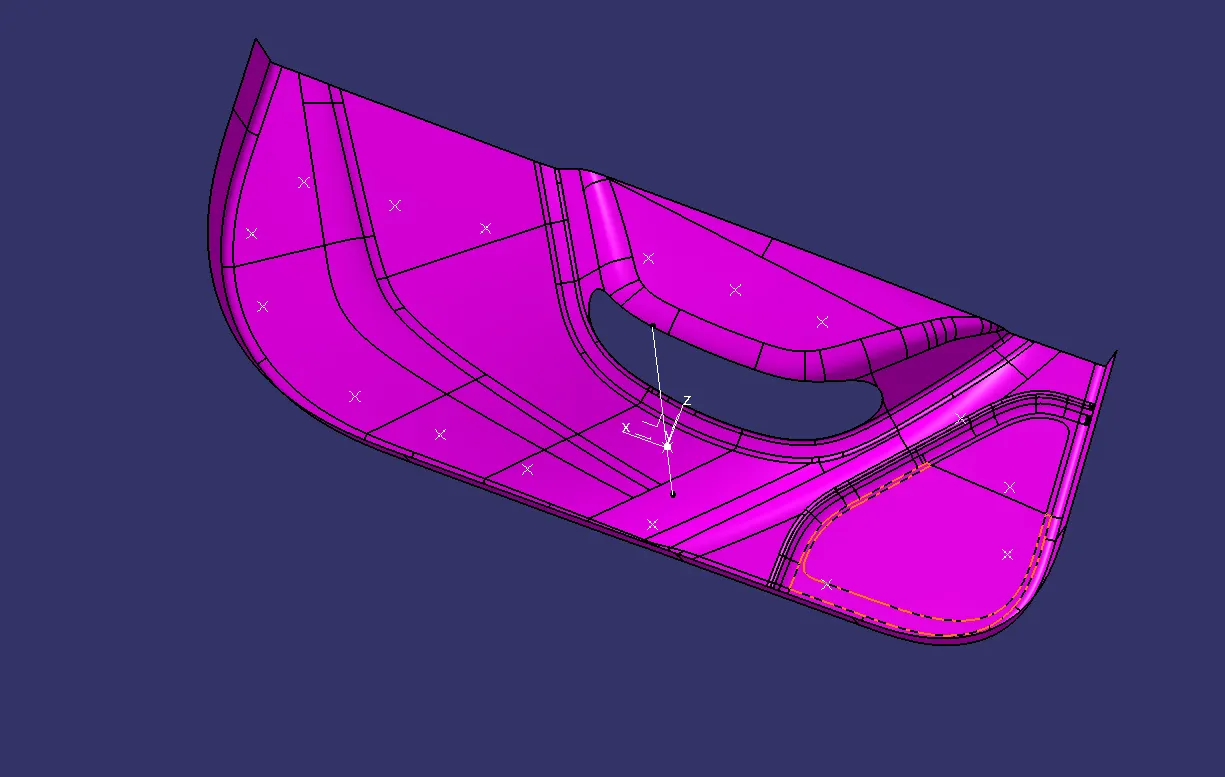
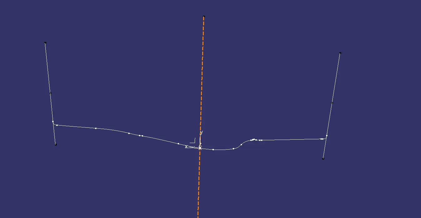
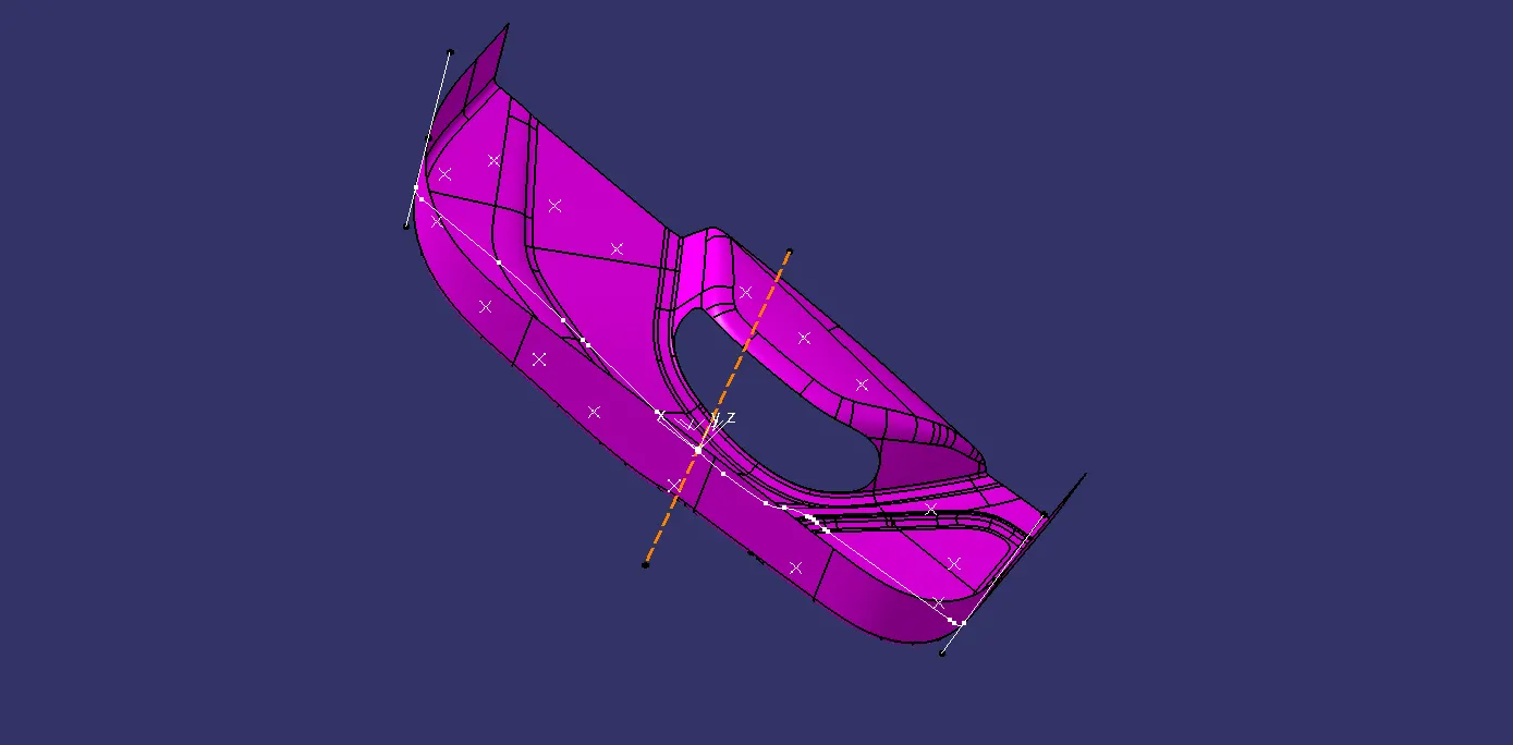
Before creating the Tooling axis check if there is any gap in the Class A-surface by Join or Boundary Command, To create the tooling axis first extract one surface from the Class A-Surface then create a point on that surface by taking the middle point, afterwords will create a temporary line with the point direction and perform the draft analysis on it. If the draft analysis comes out green then the line is the Tooling axis otherwise will intersect the surface using the intersect command and then will draw to line and create a line bisecting the two lines and will get the Main tooling Axis.
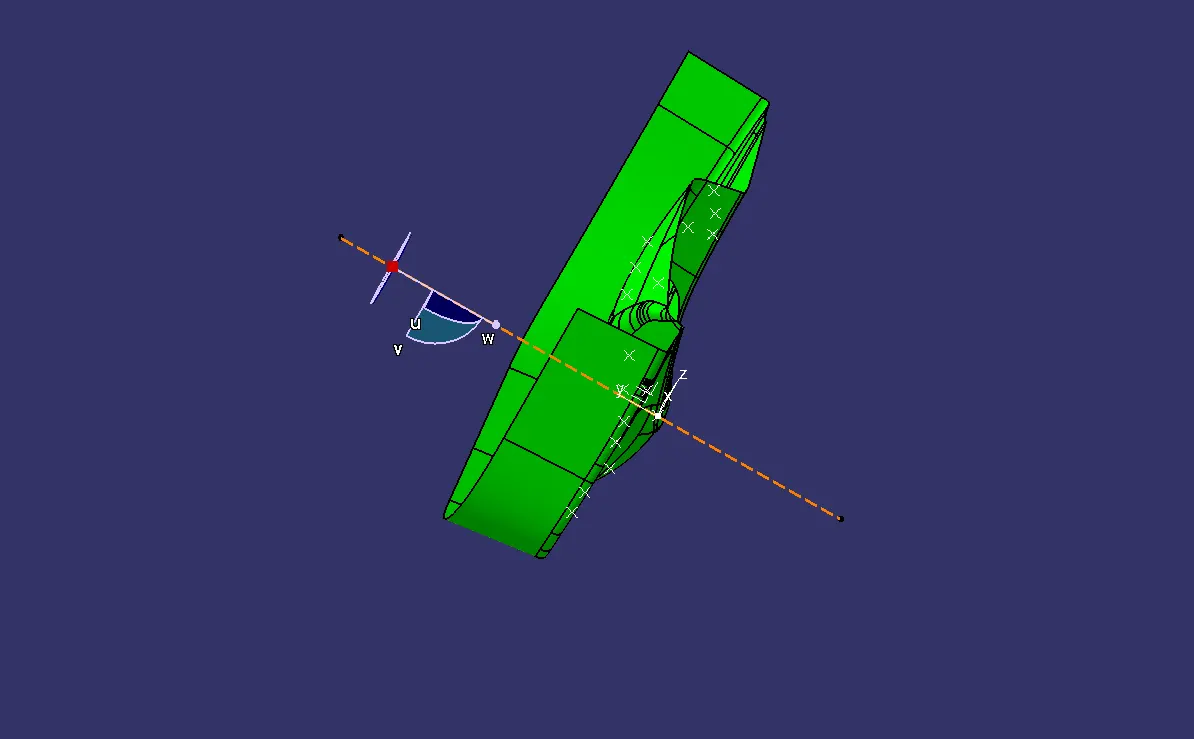
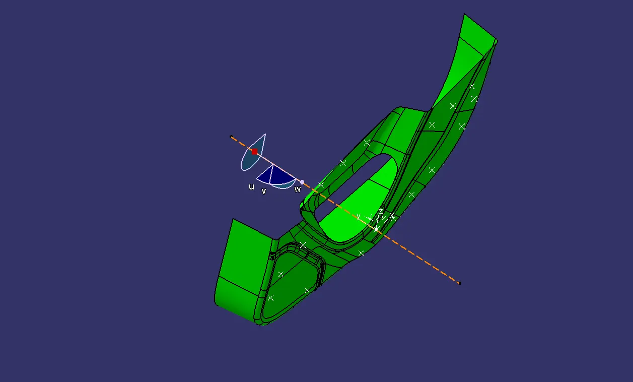
DRAFT ANALYSIS ON CLASS A:-
Now will perform the draft analysis on the Class A surface to check whether the Tooling axis created is lying under the given draft analysis value which is 0-3 degrees.
CLASS B-SURFACE CREATION:-
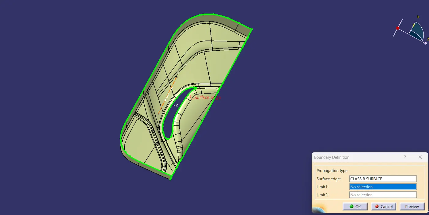
Now will work on the formation of Class B-surface creation, will offset the Class A-surface to 2.5mm in the inner side. Then will get an offseted surface which will be the B-surface, there will be some gap in that surface will have to work on that by using the multiextract, boundary, and join command to completely form a closed surface with a single boundary enclosing the whole surface.
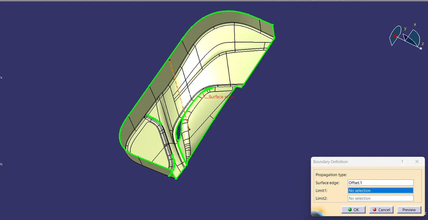
The final B-surface should look like the below image attached, there should be no gap and no extra boundaries on the B-surface.
CLASS C-SURFACE CREATION:-
After creating the Class B-surface will work on the creation of Class C-surface. Will unhide the Class C-surface then extract the boundary of the Class A-surface sweep it with reference to the surface at 90 degrees inside then will join the two extracted and sweep boundaries of the Class A-surface.
That's how the extracted boundaries will look like in the below image.
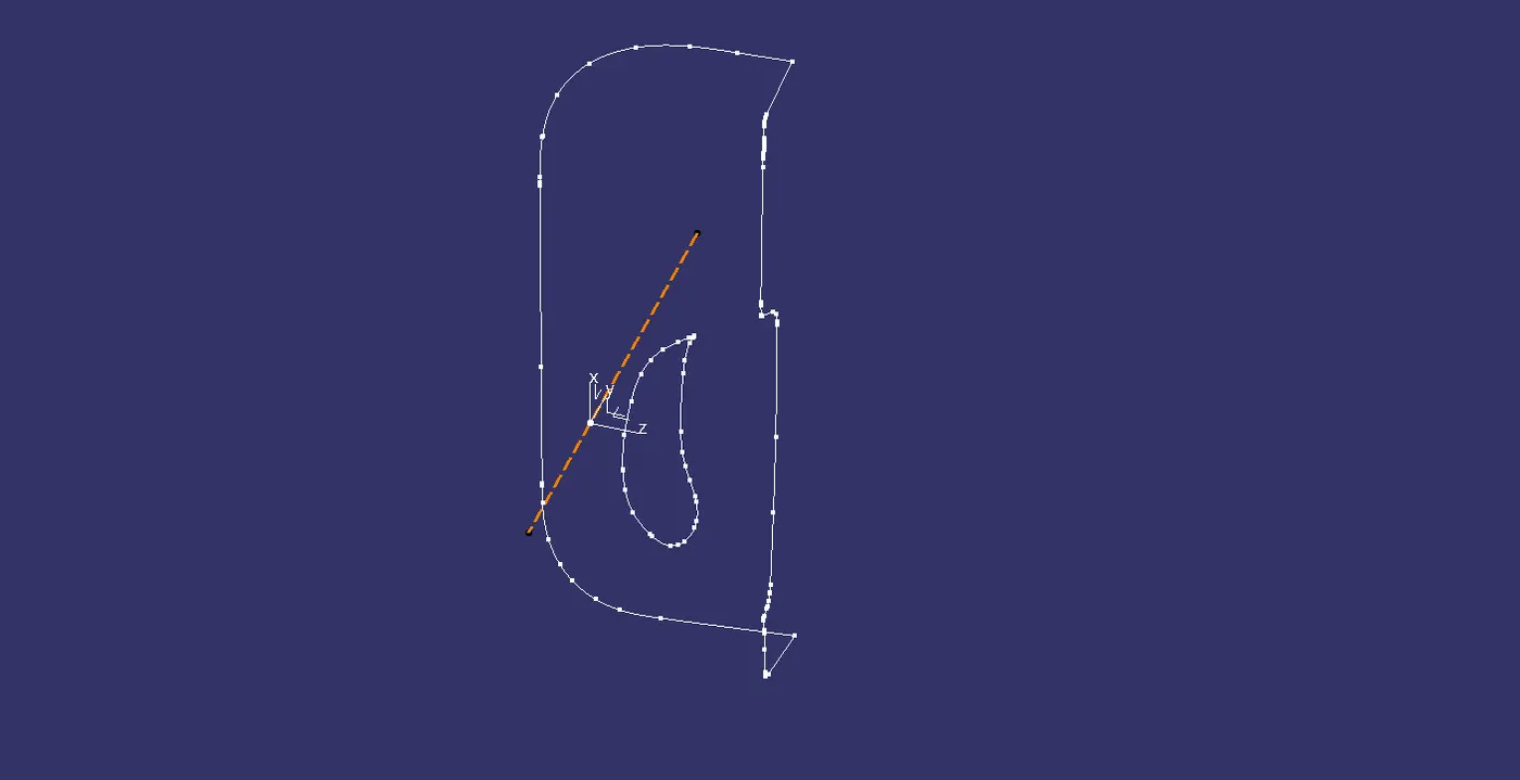
Now will sweep those two boundaries with reference to the surface at 90 degrees.
The below image shows how the sweep will be.
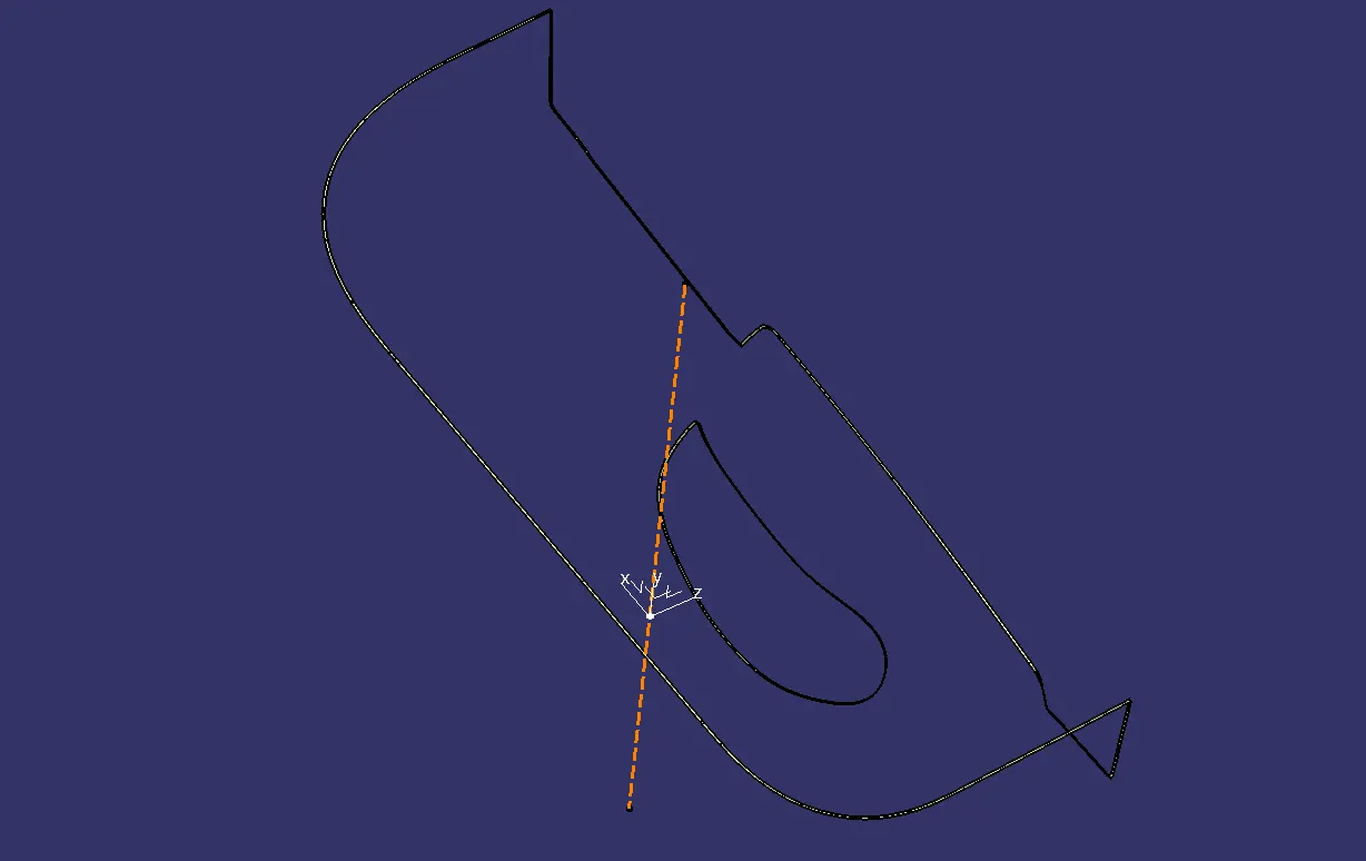
Then we join both sweeps and create a final Class C-surface.
FINAL JOIN OF CLASS A, B AND C-SURFACE:-
Finally will work on creating Final Join by joining all Class A, B, and C-surface together.
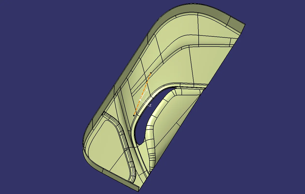
There will be some issues while creating the Final surface like the surface will not be joined completed together, for work on that with join or extract command.
FORMATION OF CLOSED BODY:-
Now will form a closed body from the surface we created but before forming the closed body surface we have to first check whether there is any boundary coming in our surface or not, if no boundaries coming then we are good to form the surface otherwise we have to work on it.
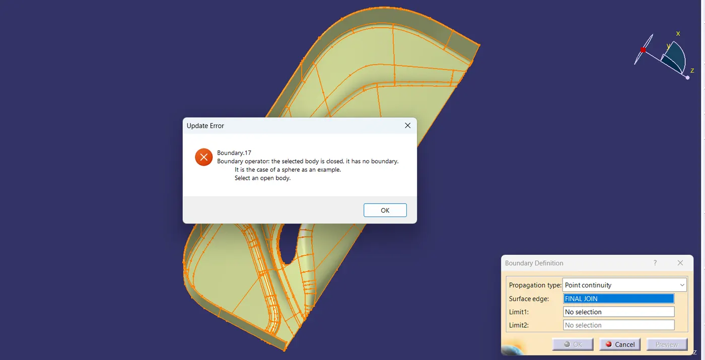
As we can see after clicking on the boundary command and then clicking on the surface will get an update error that there is no boundary in the surface, that means there is no gap in the surface and we can ahead to create the closed body surface.
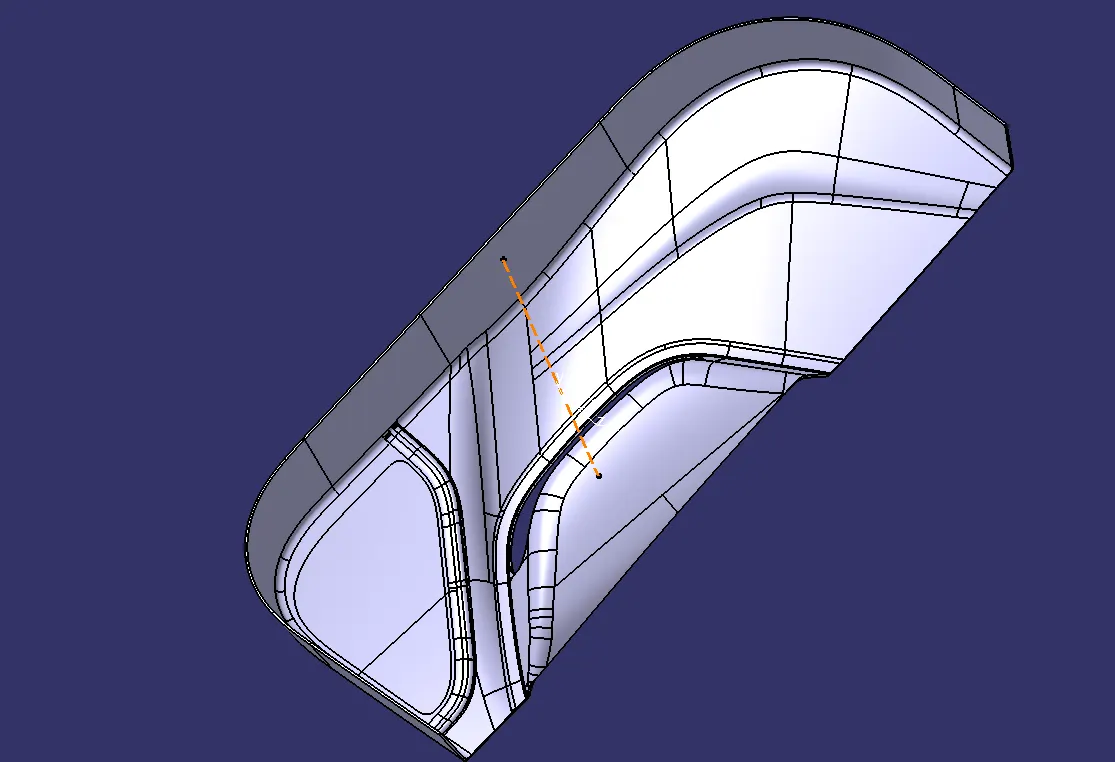
That's how our closed body surface will look like.
CREATION OF LOCATORS:-
After creating the solid body will work on the creation of the locators. Will take point on the surface or can take point in between the two points given for heat stakes and then will create a sketch on that point by creating a plane on that point.
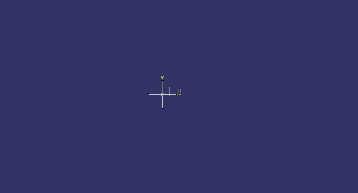
Sketch of Locator.
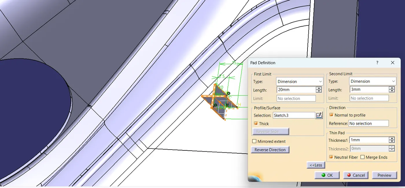
Now will extrude or pad the locator sketch.
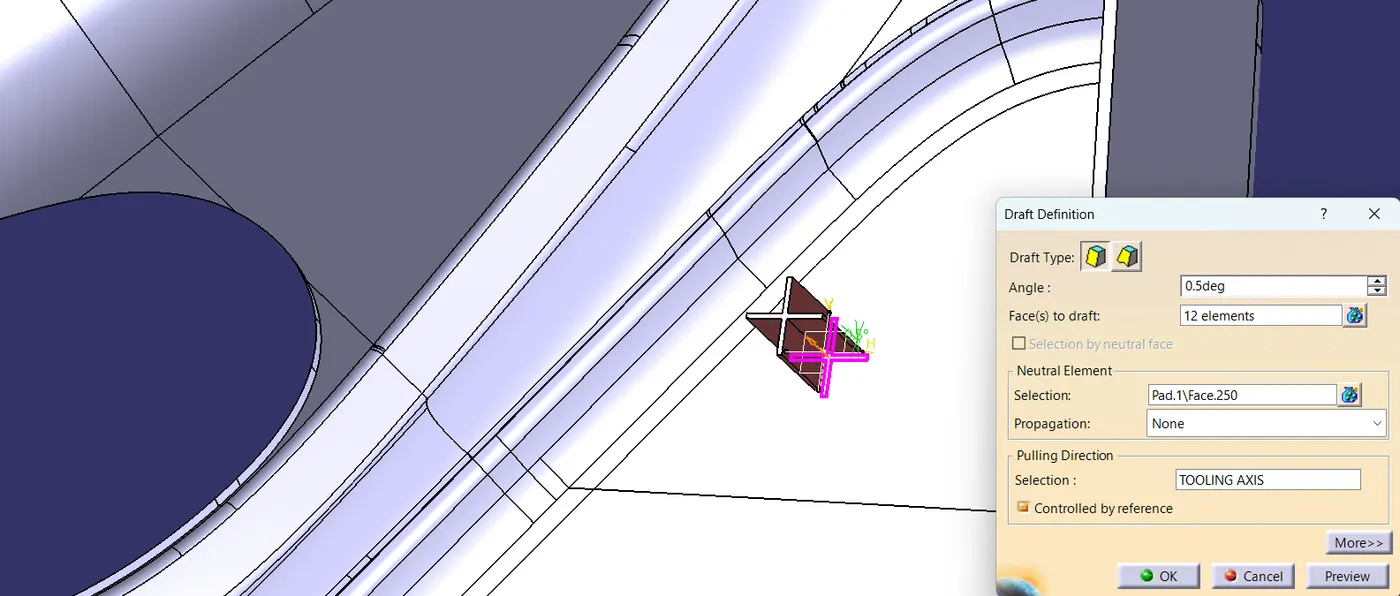
Now will draft the padded surface.
After that will chamfer and fillet the product.
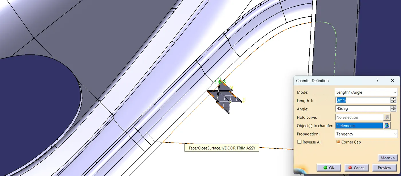
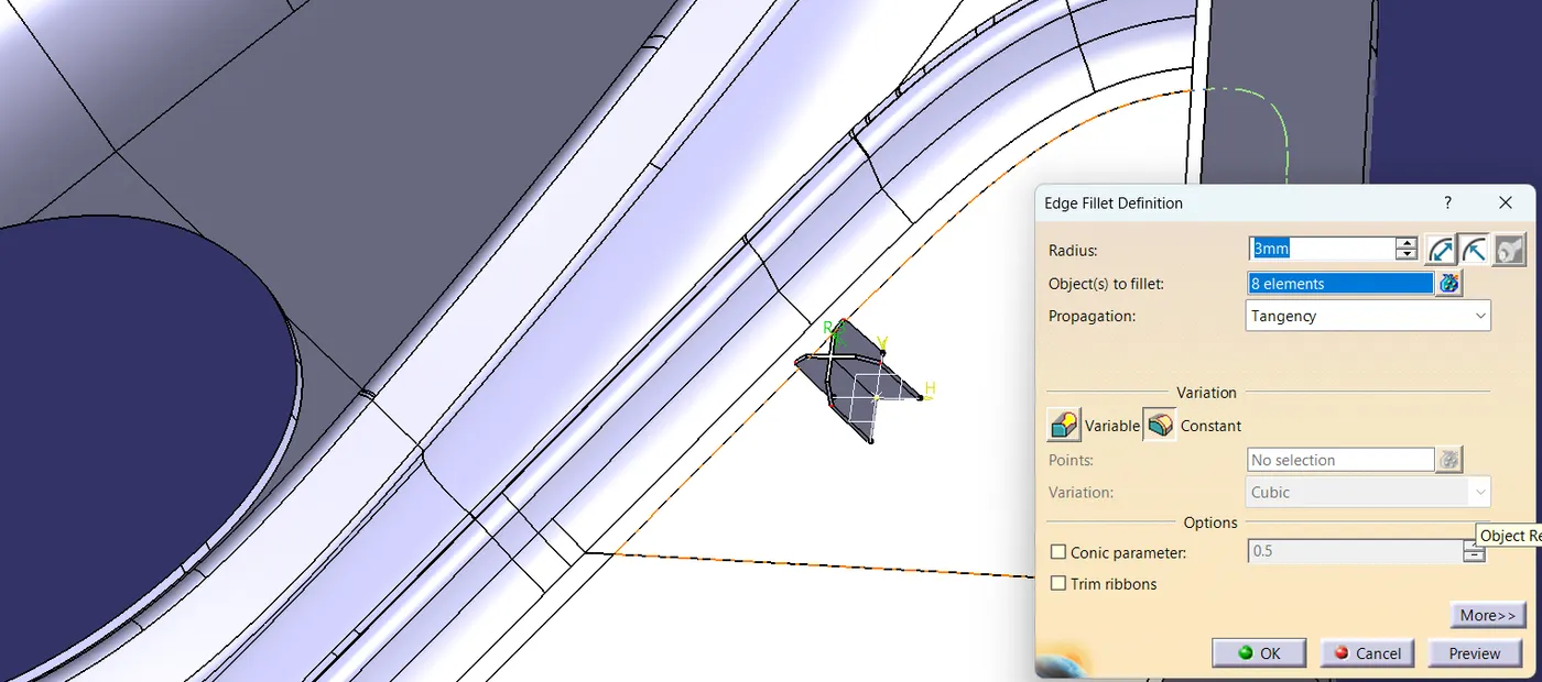
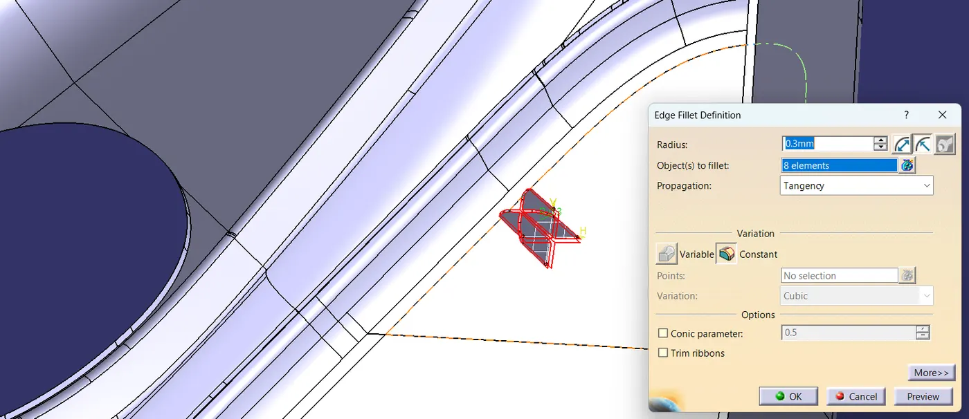
After that will create another point on the surface where we have to create the second locator then copy the first locator and paste it with the same result, translate it from point to point, and form the second locator.
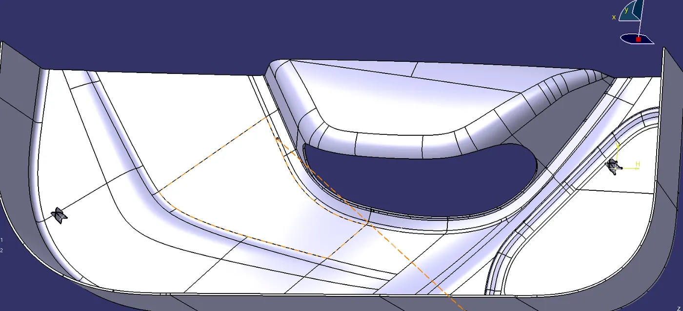
After creating the both Locators will do Boolean Operation(Union Trim) with the main Part Body.
CREATION OF HEAT STAKES:-
After the creation of locators, will move to create the heat stakes with the help of points given on the class A surface. Firstly we create a plane on it and then will create a sketch on it.
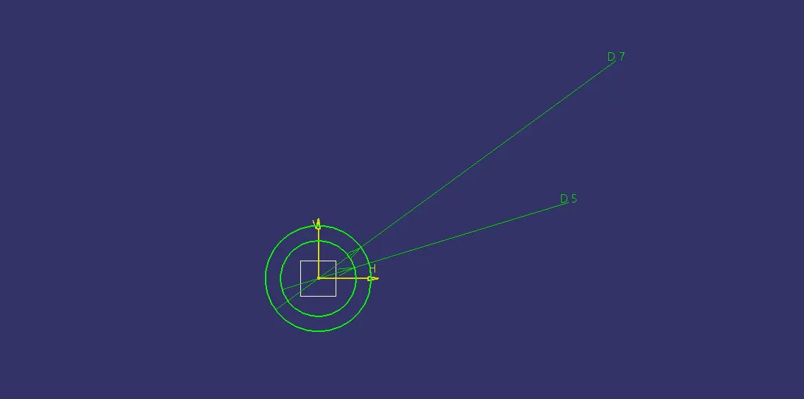
Before creating the sketch measure the thickness of the surface and then according to it draw the circle.
After that will pad or either extrude the sketch.
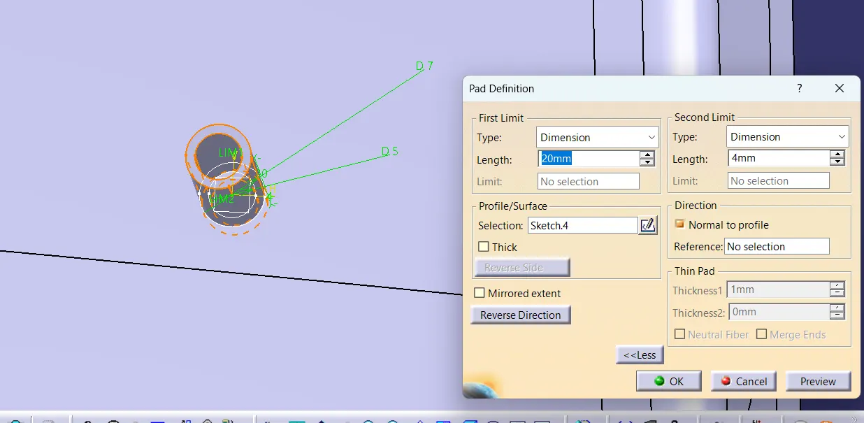
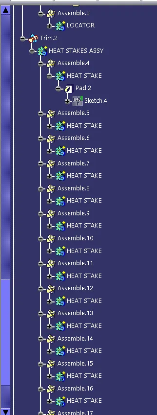
After that will copy the same padded Heat Stake and copy it till we create the Heat Stakes on the given points then we assembly all the heat stakes into one body and then do Boolean Operation(Union Trim) with the Main Body part and create the final Product.
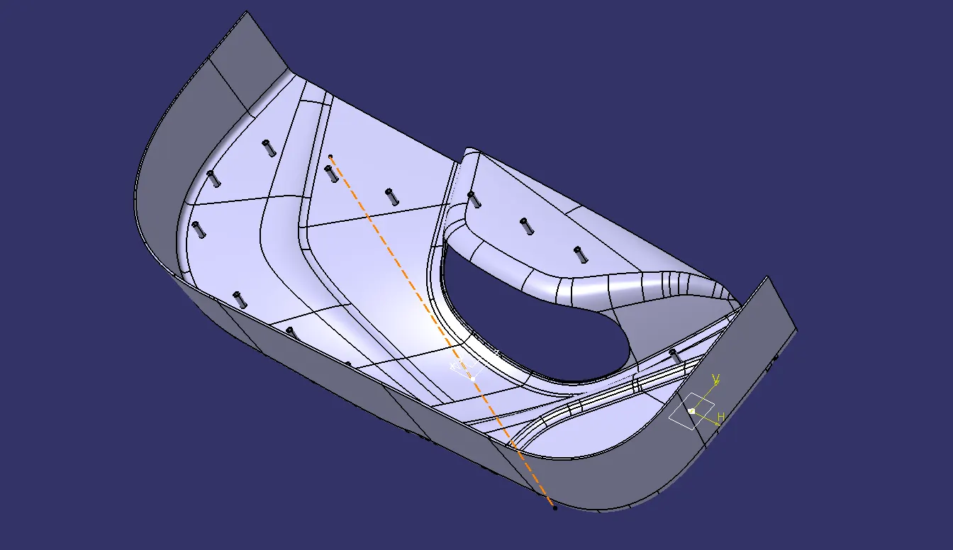
That's how the Heat stakes will look after forming on all points.
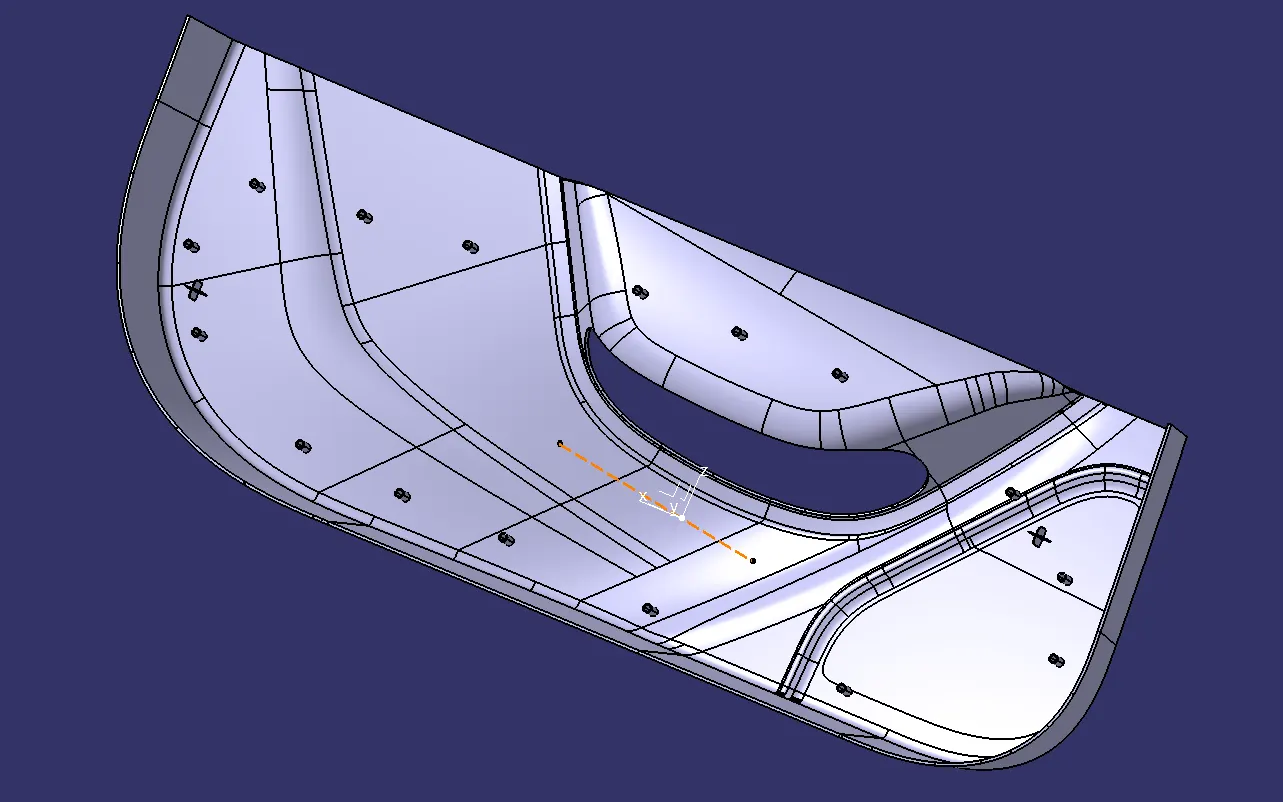
The Final product should be like in the below image.
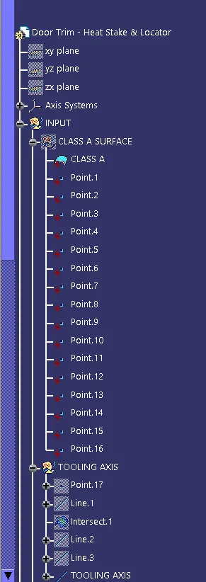
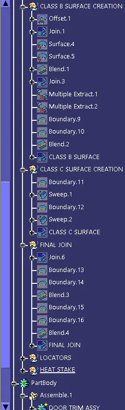
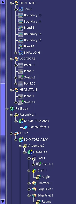
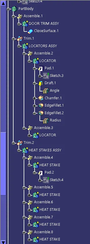
EXPANDED TREE STRUCTURE:-
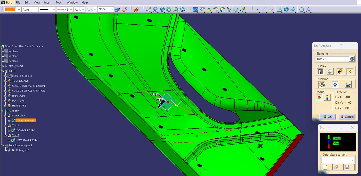
DRAFT ANALYSIS ON FINAL PRODUCT:-