Week 9 - Challenge 3 - Bumper
BUMPER DESIGN
AIM:
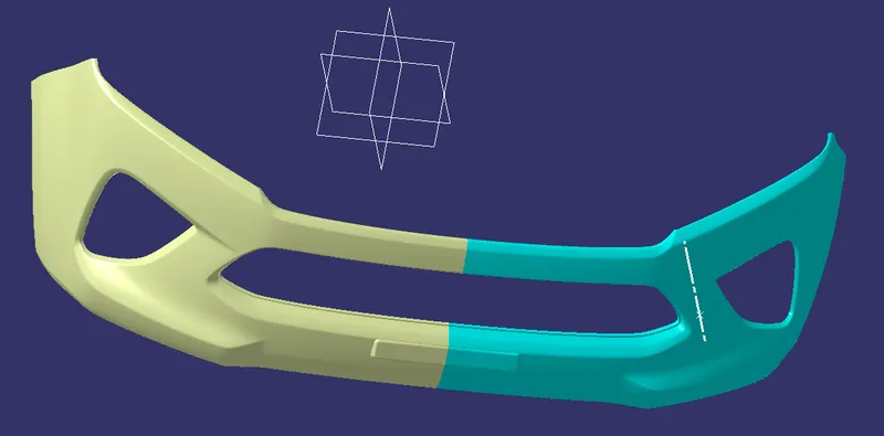
To make a model of bumper using the given A surface
INTRODUCTION:
CLASS A SURFACE:
A Surface made by designer which is given as an input to the plastic modeler to work on. It is aesthetic surface and the outer most surface.
CLASS B SURFACE:
A surface below a certain thickness from the class A surface is class B surface. this is the surface that contains engineering aspects of a model.
CLASS C SURFACE:
A surface which joins Class B and Class C is Class C surface.
Creation of tooling axis:
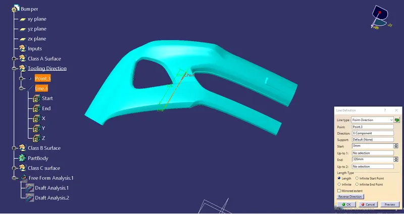
Tooling axis is the direction in which a core or the cavity of mould opens. This axis is very important to determine of the compenent in mold, core and cavity design.
The tooling axis is creatred by the inertoia method by using the steps as follows.
Creating a point using point feature and directly we can create a line as shown in image.
DRAFT ANALYSIS FOR A SURFACE:
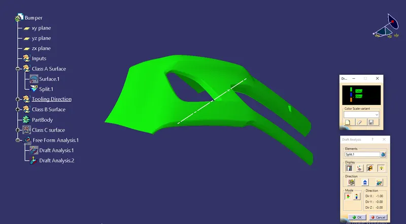
First we need to analys the model and then choose dummy axis in X and Y direction.
As we intersection to proceed we observed that the side walls are not given any draft.
Hence we assume the axis normal to the base surface and parallel to side walls.
It will shows an dialoge box by that which we can fix the the Draft analysis.
DRAFT ANALYSIS FOR THE FINAL PLASTIC COMPONENT:
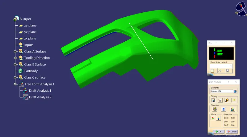
After creating the entire model we need to check the draft analysis
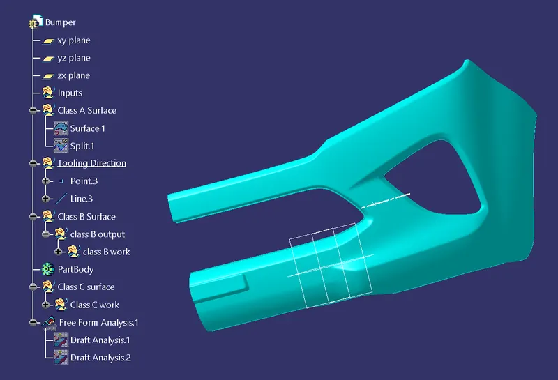
ISOMETRIC VIEW :
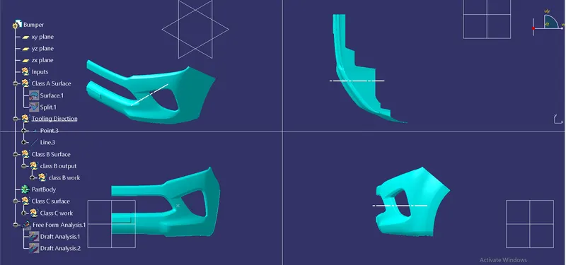
ORIENATION VIEW:
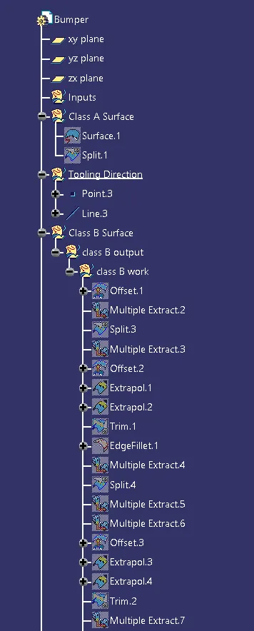
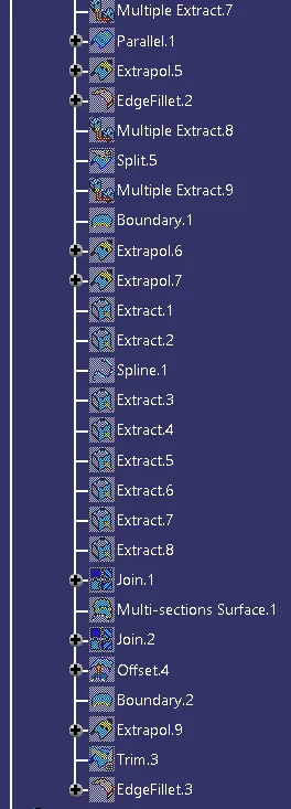
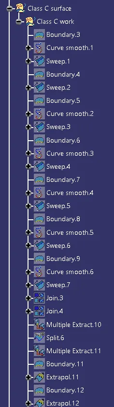
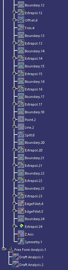
Tree Structure:
FINAL PLASTIC COMPONENT OF BUMPER: