Week 9 - Challenge 3 - Bumper
REPORT ON BUMPER DESIGN USING DRAFT ANALYSIS METHOD
- AIM : To Create the Bumper Plastic component through the given Class-A surface. To begin with, the tooling axis for the given Class-A Surface should be created meeting the requirements of the draft angle and at the end perform the Draft analysis on the model.Take the Thickness of the component to be 3mm.
- CLASS A SURFACE : All visible external surfaces (such as bumpers, grilles, lights, and body panels) and all visible surfaces of see-touch-and-feel interior components (such as dashboards, seats, and door pads) are produced as Class A Surfaces in automobile design software. This can also apply to carpets, mud flaps, trunk panels, and cosmetic covers in the engine compartment. This surface is 0 millimeters thick.
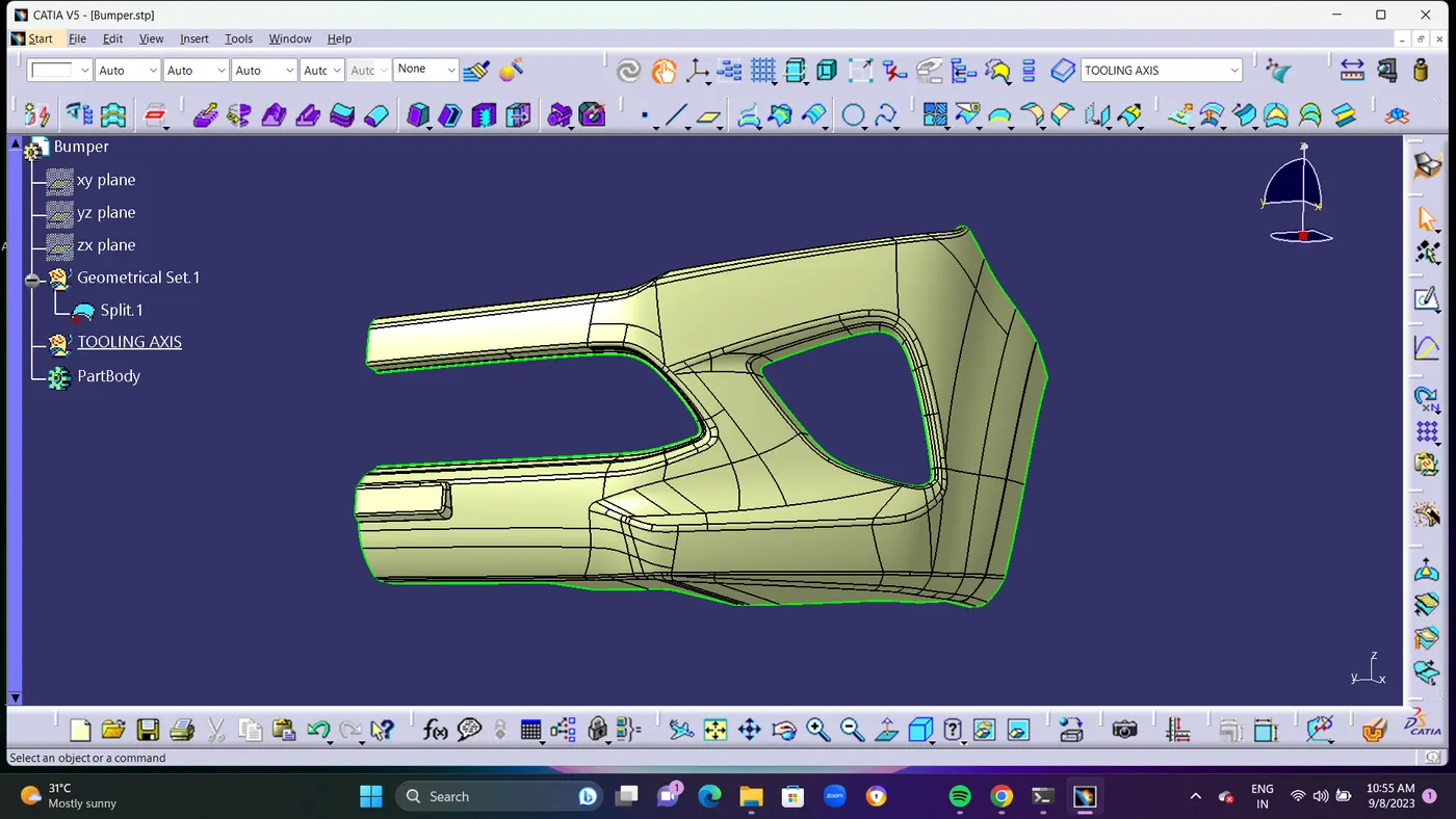
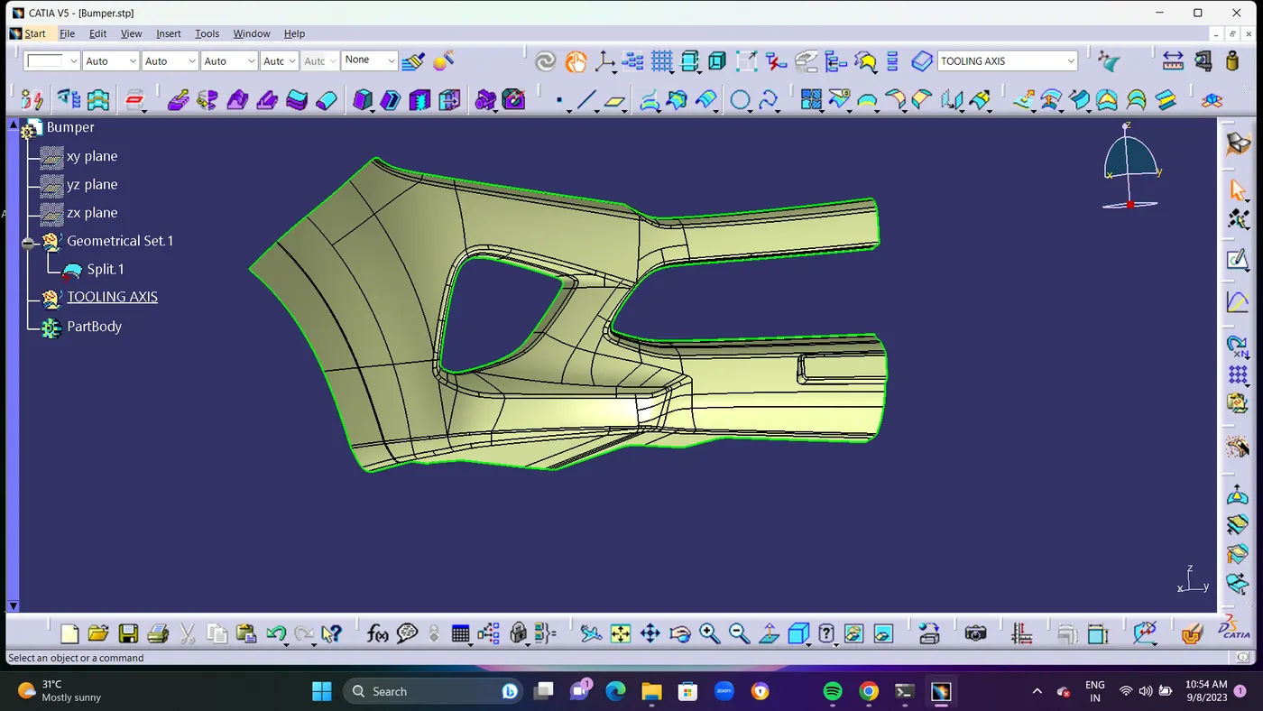
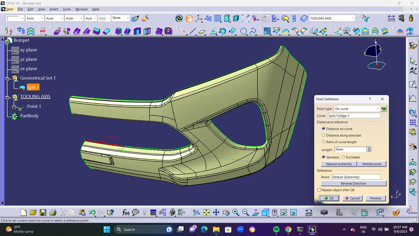
- TOLLING AXIS : Tooling axis or tooling direction is main consideration for plastic part and mold parts because it defines movement of mold part and possibility of plastic part to come-out from mold part (Core and Cavity). In Molding machine arrangement is given to open the mold along a direction which is known as Tooling Direction. The mold is built from two separate halves (Core and Cavity) and tooling direction basically define the direction of mold pulls apart. Tooling direction is known as primary direction.
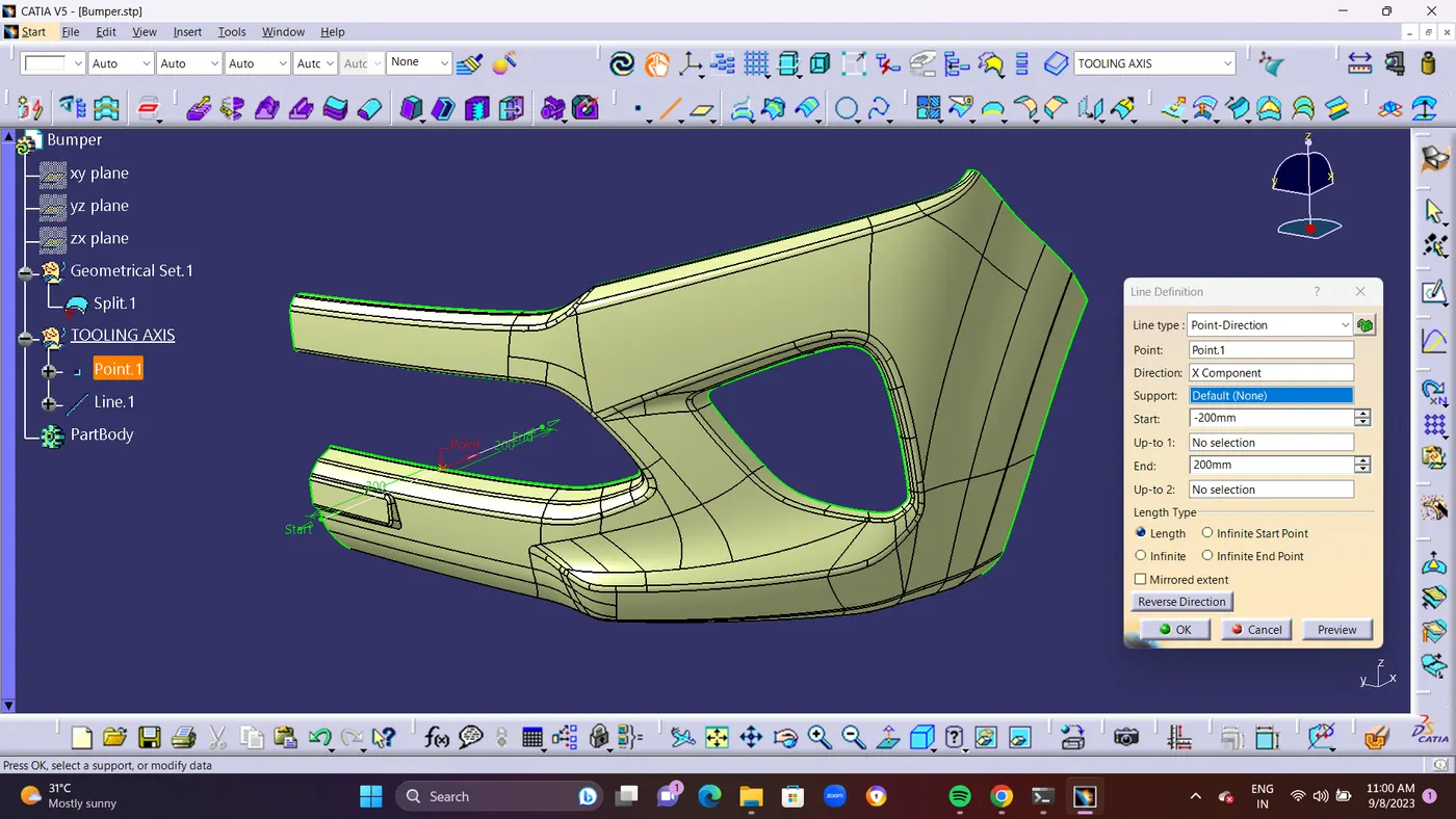
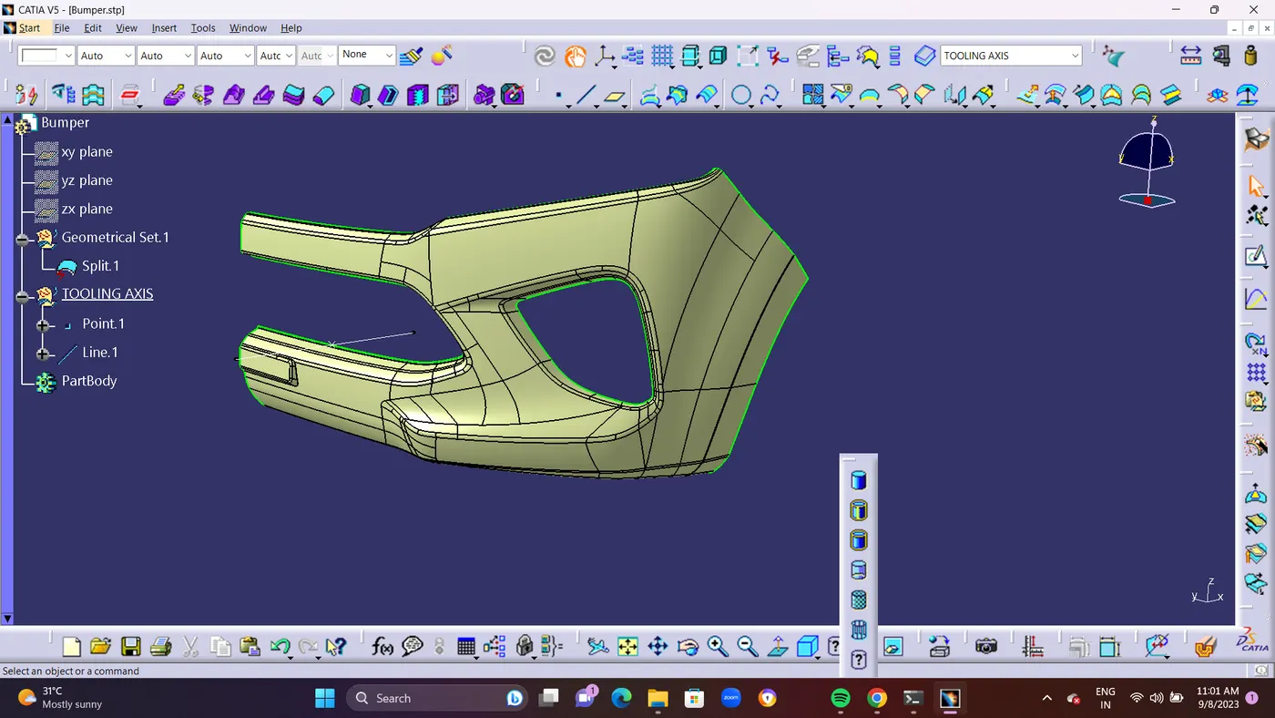
- Here I have created a tooling axis. First of all I extract a base surface and create a mid pont on it. And then I create a line through this point with perpendicular to base surface. And then I performed draft analysis ans I saw every thing is ok. Then finally it is my tooling axis.
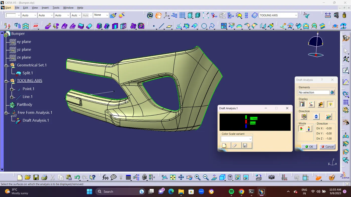
- CLASS A SURFACE DRAFT ANALYSIS : You may use the Draft Analysis command to see whether the portion you drafted will be simple to delete. This kind of analysis is carried out using color-coded zones on the studied element that correspond to certain values when the deviation from the draft direction is present at any point.
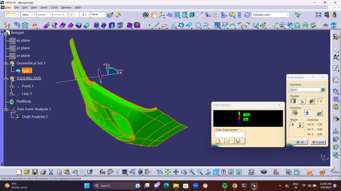
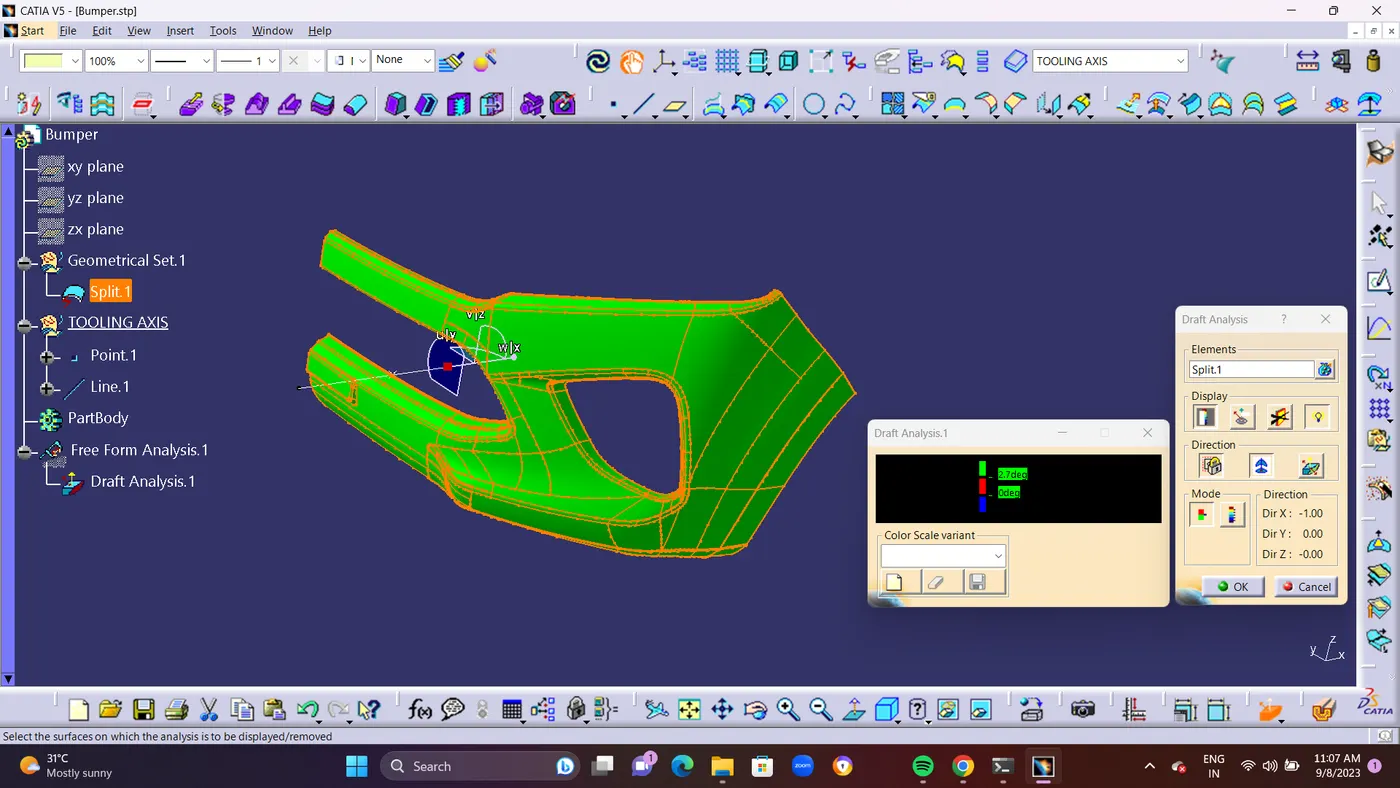
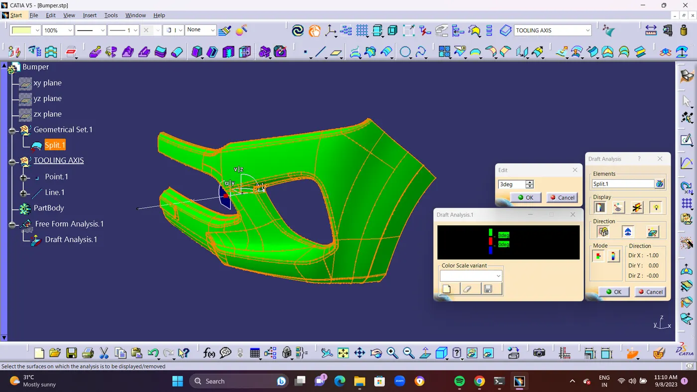
- After choosing the tooling axis, draft analysis is carried out to see if the minimal draft (3 degrees) is being maintained.
- The Draft Analysis makes it simple for the user to check a part for the correct draft angle. The degree of taper for cast or molded pieces that runs perpendicular to the parting line is referred to as a draft angle. 3D part models are suitable for draft analysis. For every 3D part file, a draft analysis may be made by
- CLASS B SURFACE CREATION : Class B is a reference surface that the design engineer creates and which is a replica of class A at a distance equal to the part's thickness.
- STEP 1 : Offset Class A Whole Surface for Creating an Class B Surface. Because of Complicated part can Be Fully Offset to Creat Class b surface From Class A.
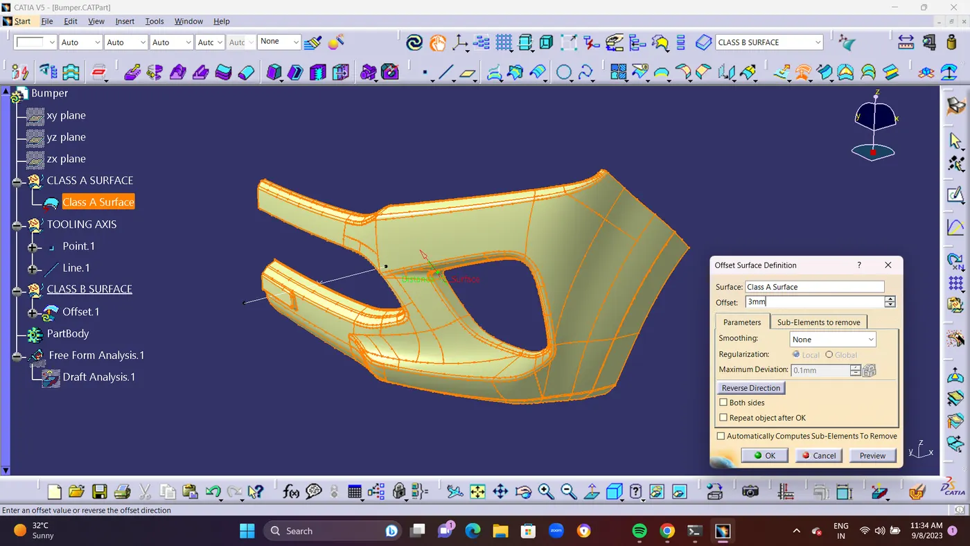

- After Offsetting Some patches are appearing in class B surface. Because of Fillets areas it cant create Fillet on it. so its shows ERROR.
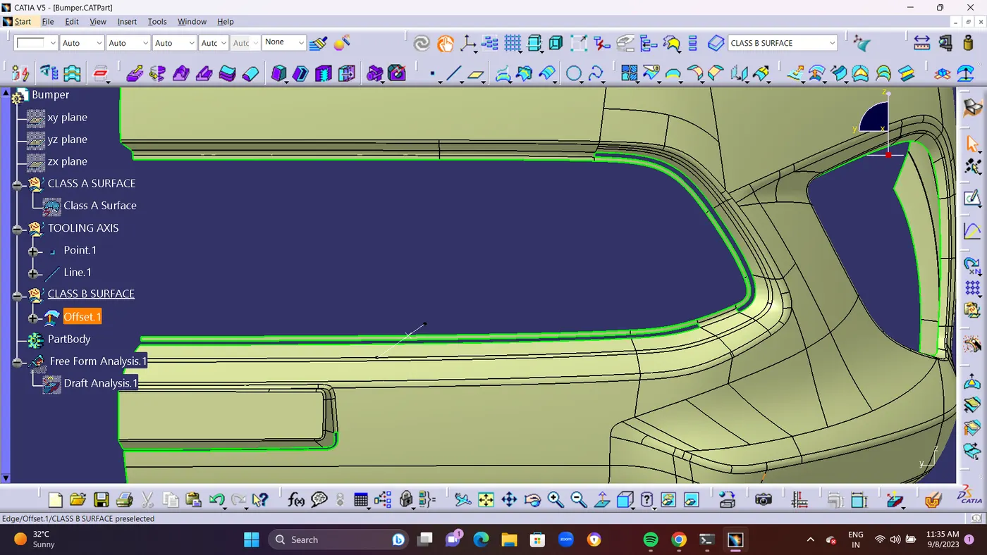
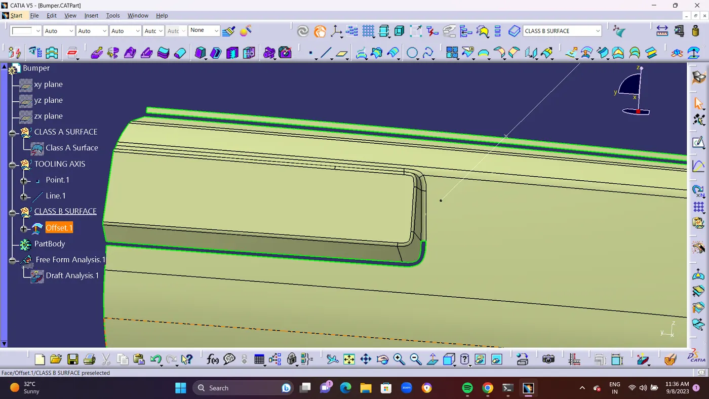
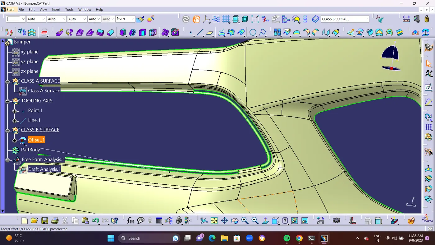
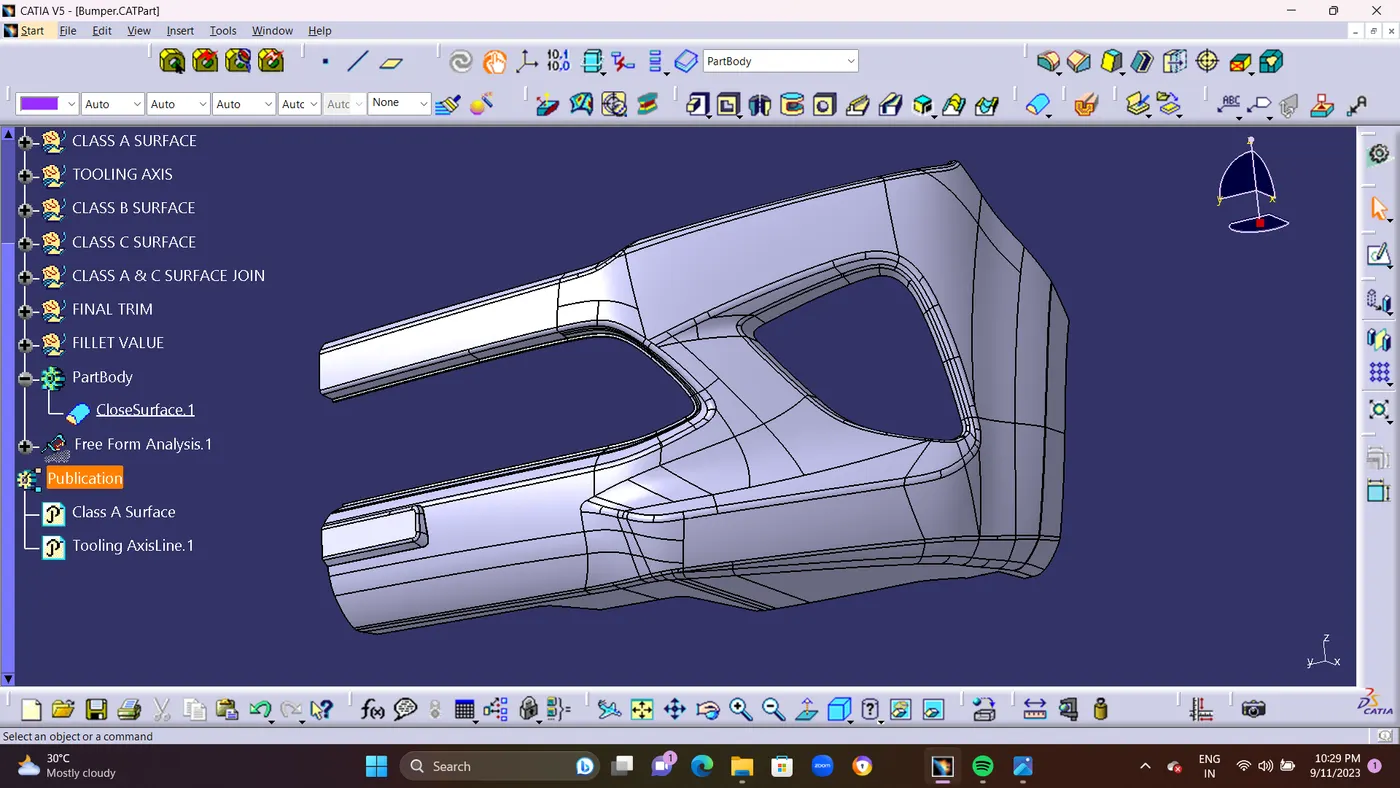
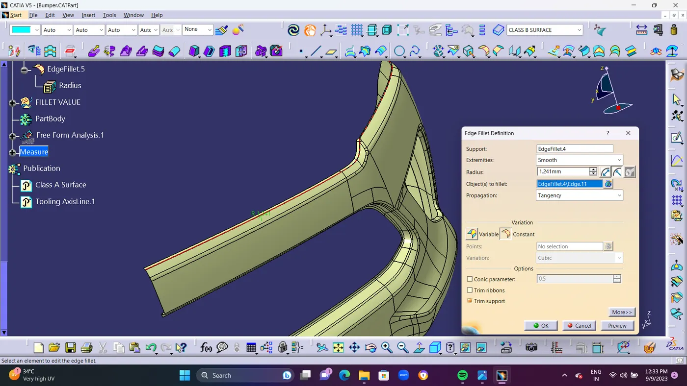
- STEP 2 : For Solving The Patches using Multiple Extract Command Seperating the pached area surfaces and Create an Boundary Line on the Multiple EXtracted Surface.Finally Extapolate It to Interconnect the Both surface for Minimum 5mm.after interconnected it. and Using TRIM Command trim the Both surface.To get Sharp edge Surface and Finally use EDGE fillet on it.
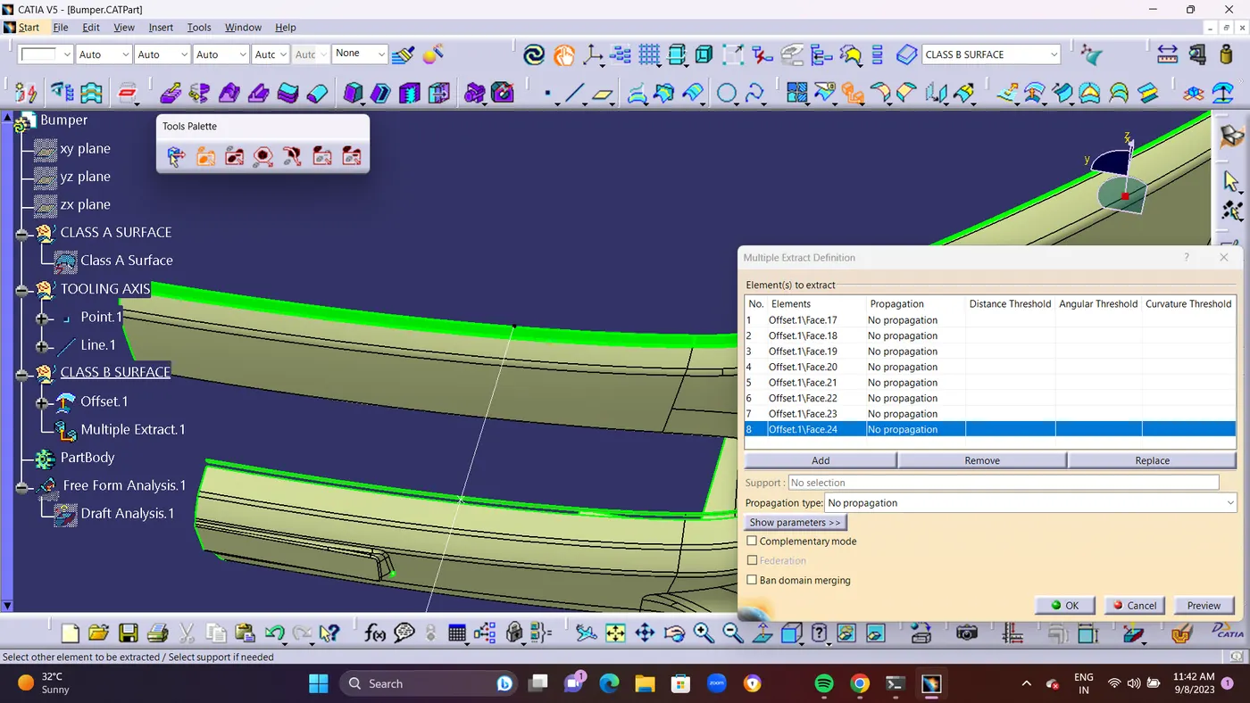
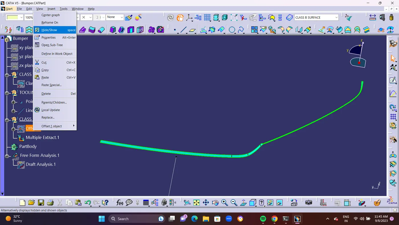
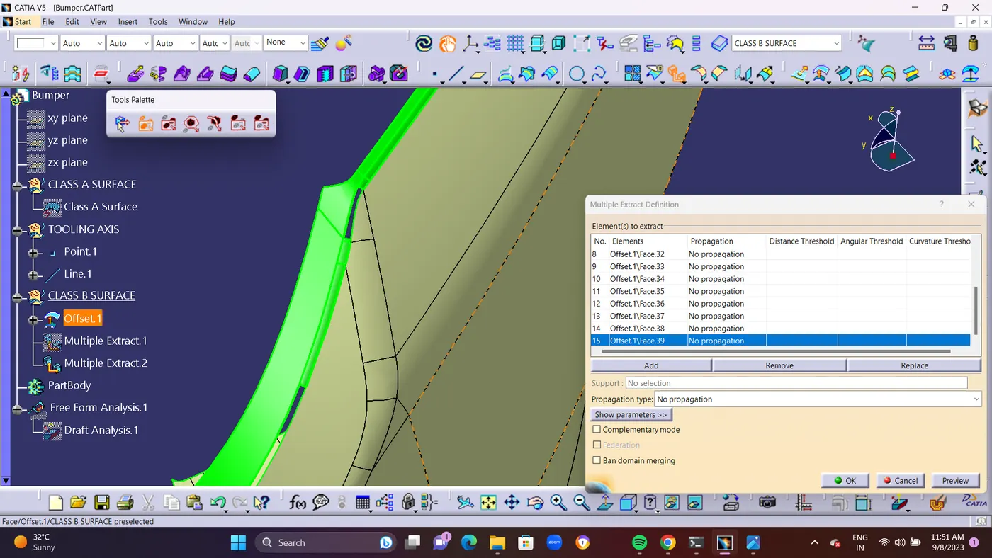
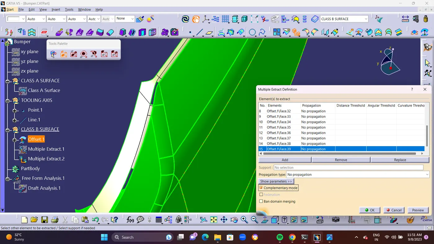
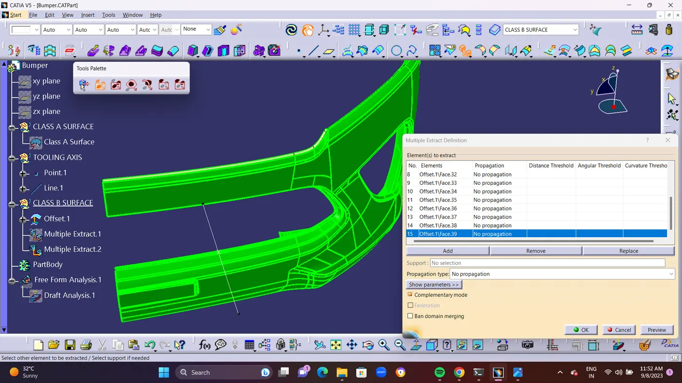
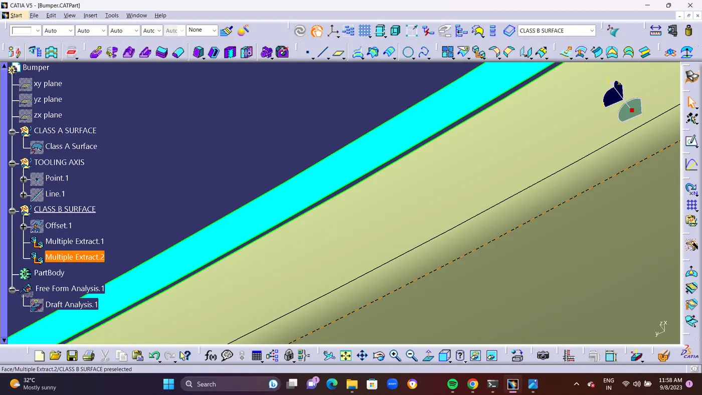
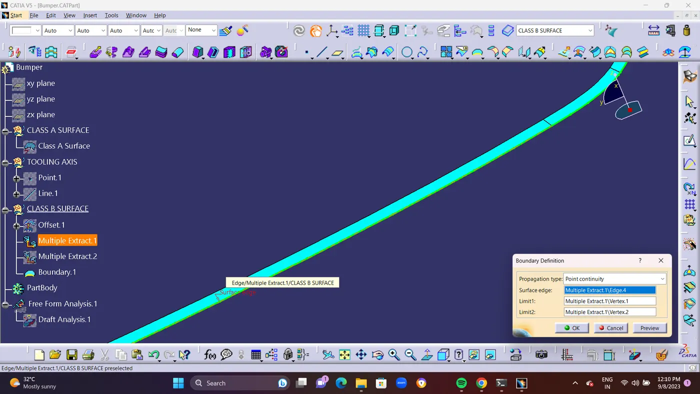
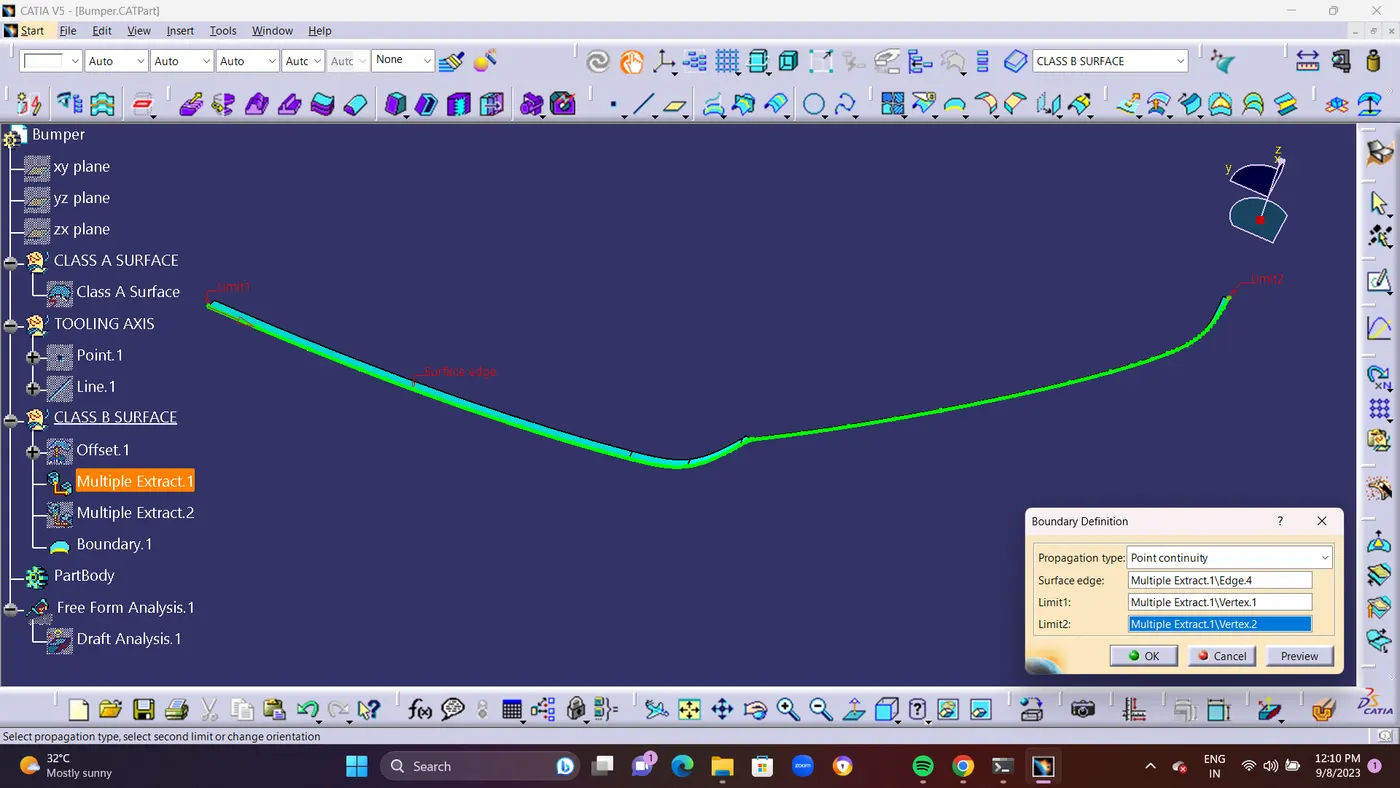
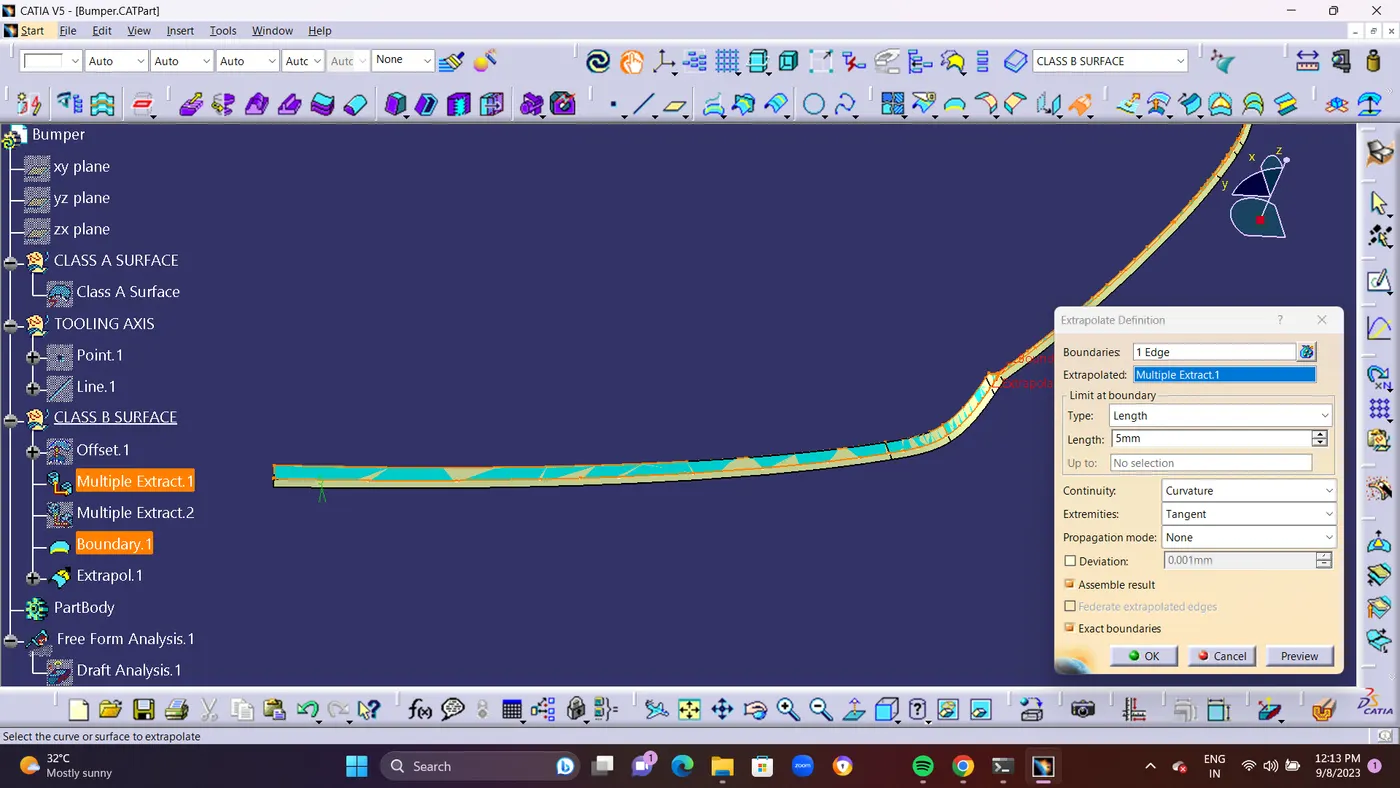
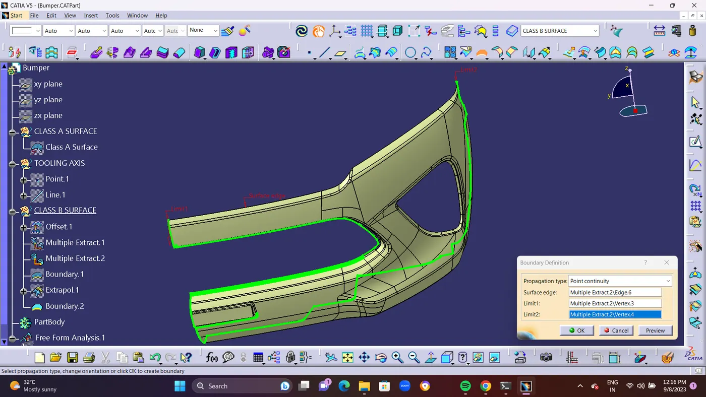
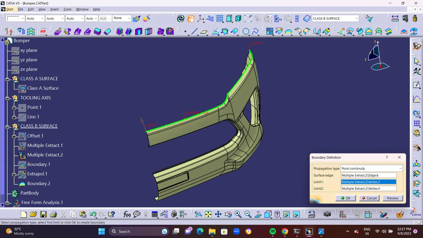
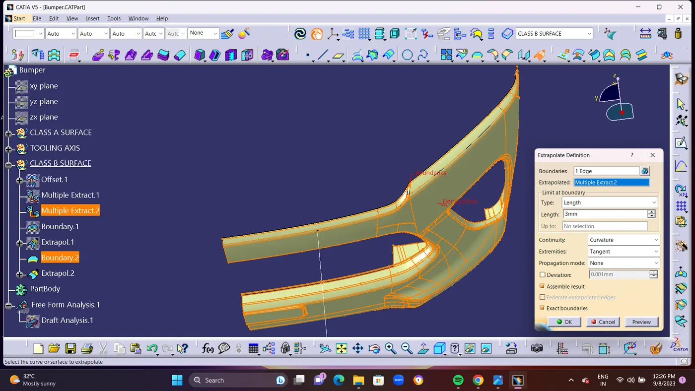
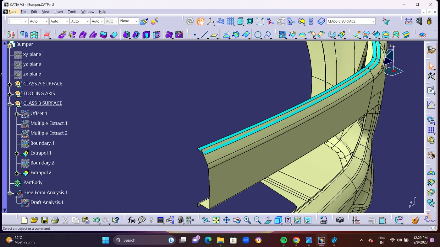
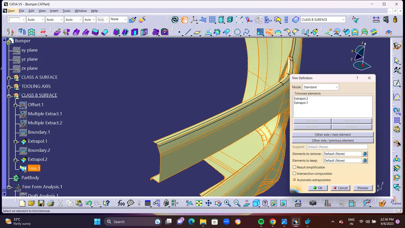
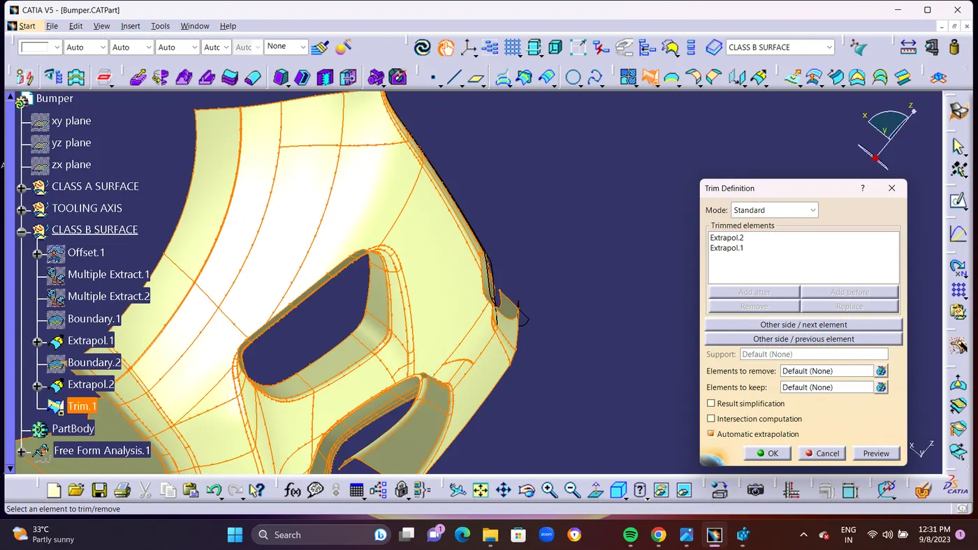
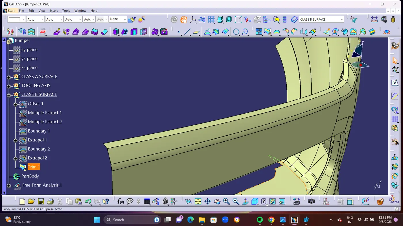
- STEP 3 : For other 2 Surface PATCHES Im going to use in different method.For Solving The Patches using Multiple Extract Command Seperating the pached area surfaces as Boundary line. and Using SPLIT Command Seperate the EXTRACTED Surface.and using Join Command you can remove unwanted surface in class B surface like fillets etc. In Join Command as an Option Called SUB-ELEMENTS TO REMOVE you should use that command for removing it.
- and take BOUNDARY LINE from the Splited surface and EXTRAPOLATE (EXTRAPOLATE-3) the Splited surface for 5mm.and JOIN Surface also be EXTRAPOLATE (EXTRAPOLATE-4) for 5mm and TRIM Both Surface ( SPLIT 1-Extrapolate 3 and JOIN 1-Extrapolate 4) to form a single surface without fillet as an sharp edge. you can give fillets before Final trim.
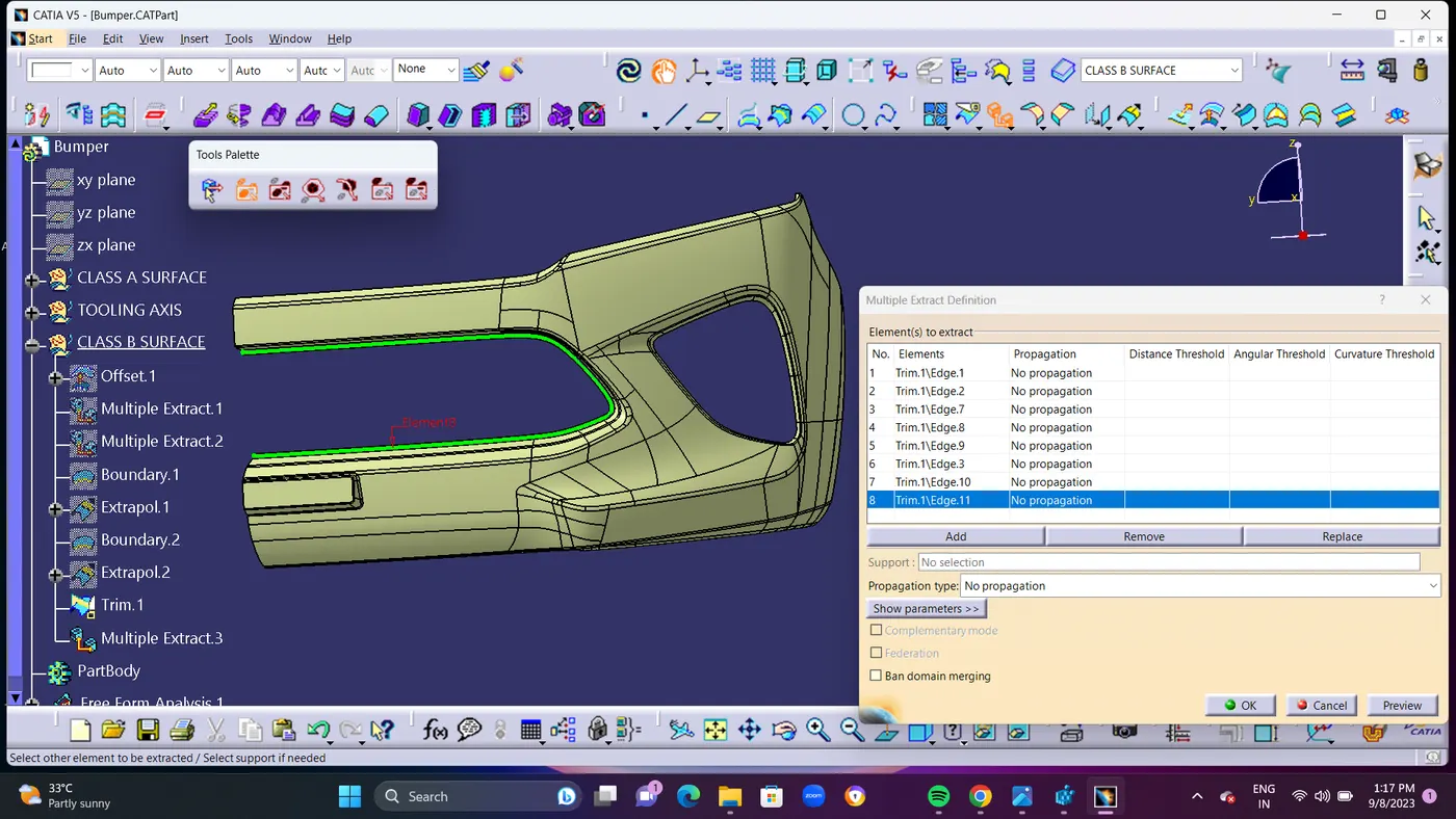
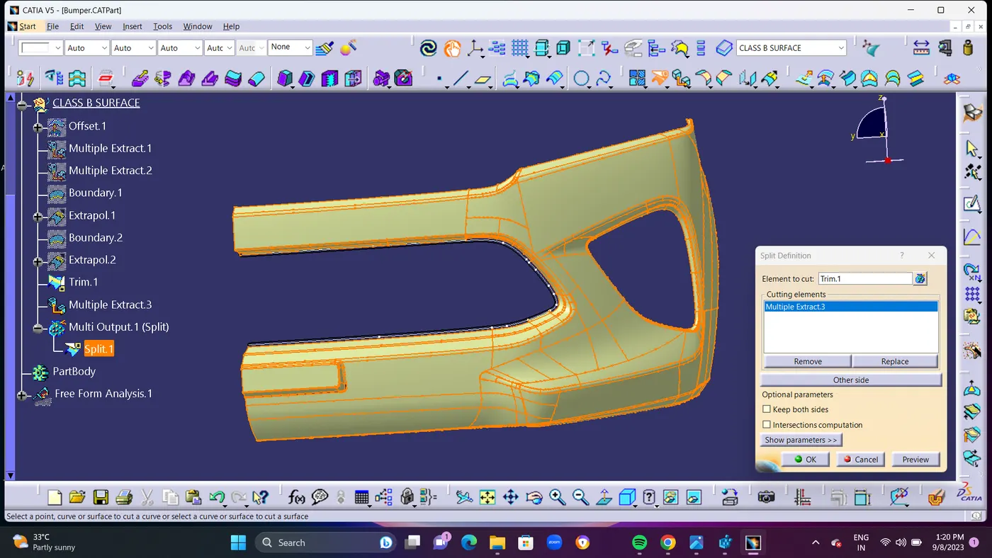
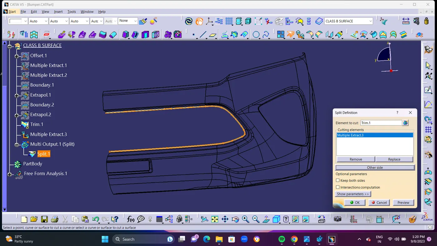
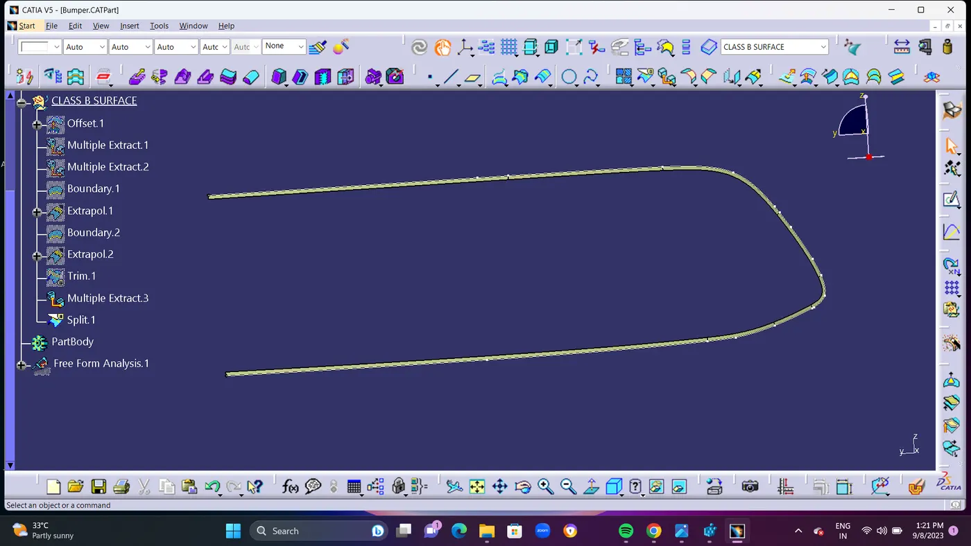
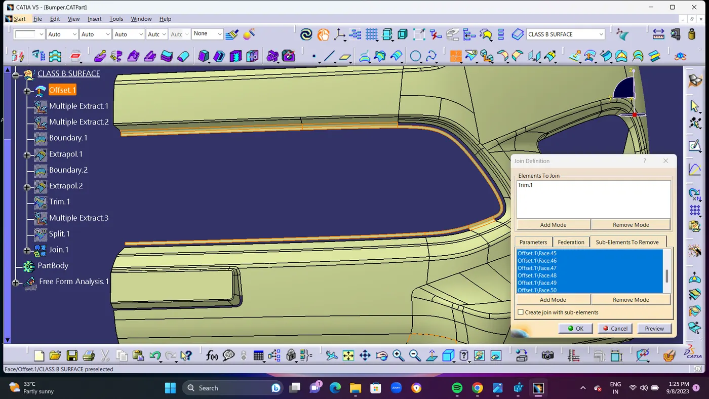
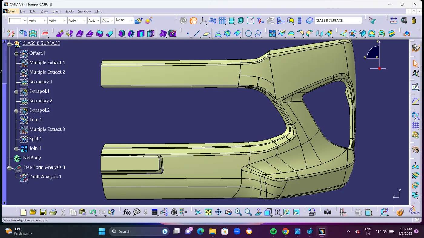
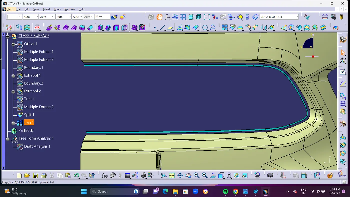
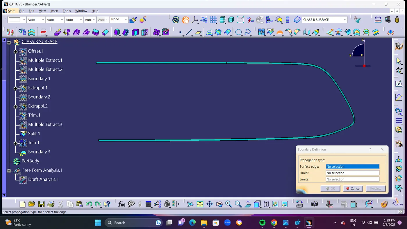
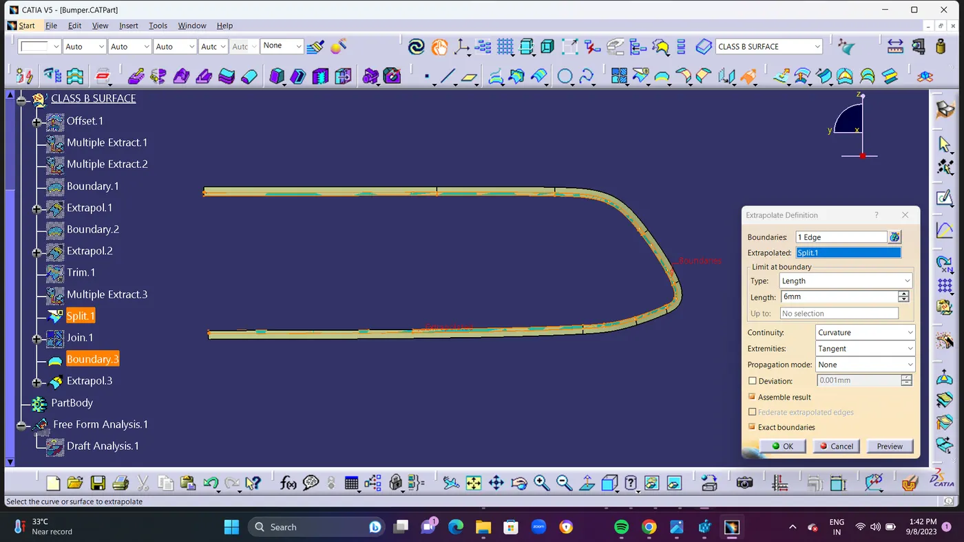
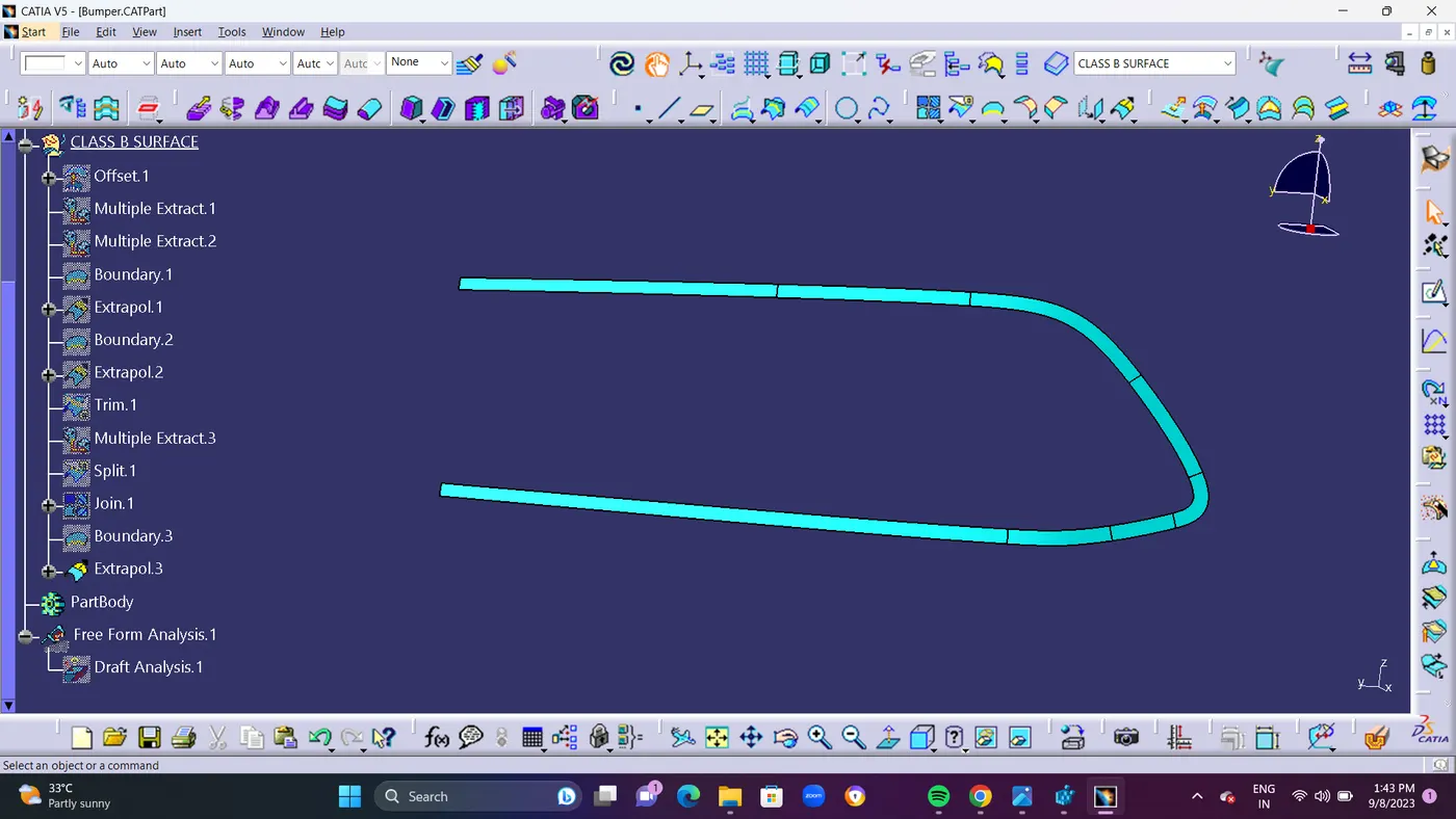
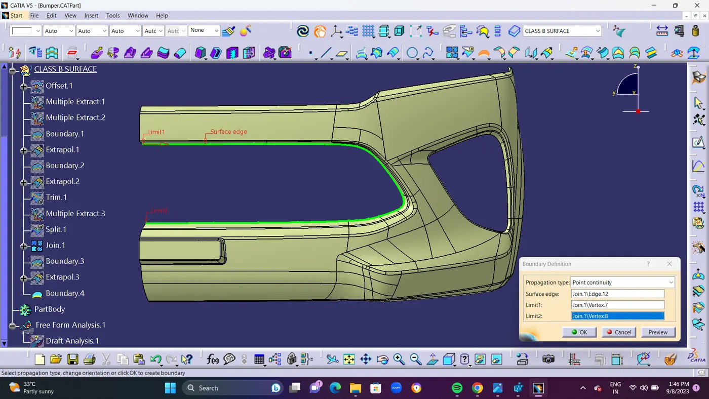
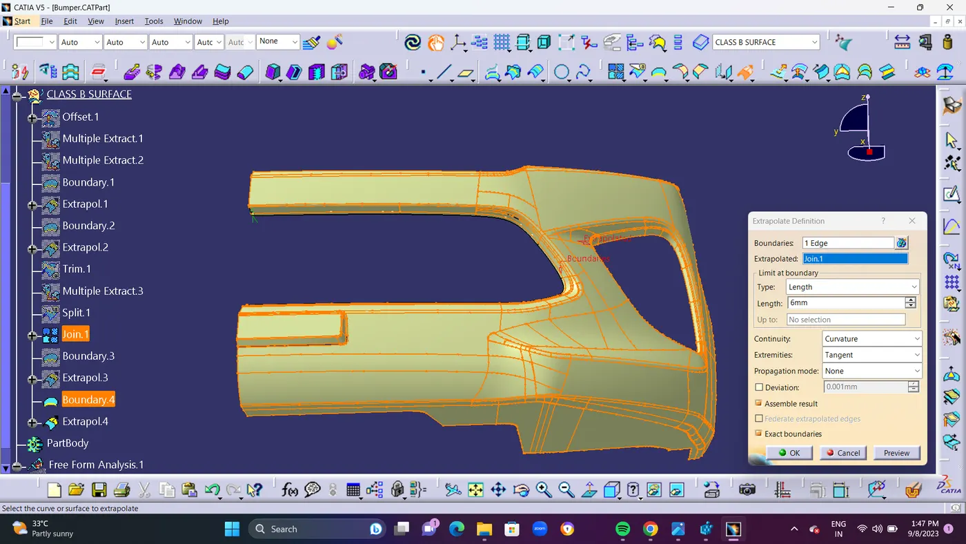
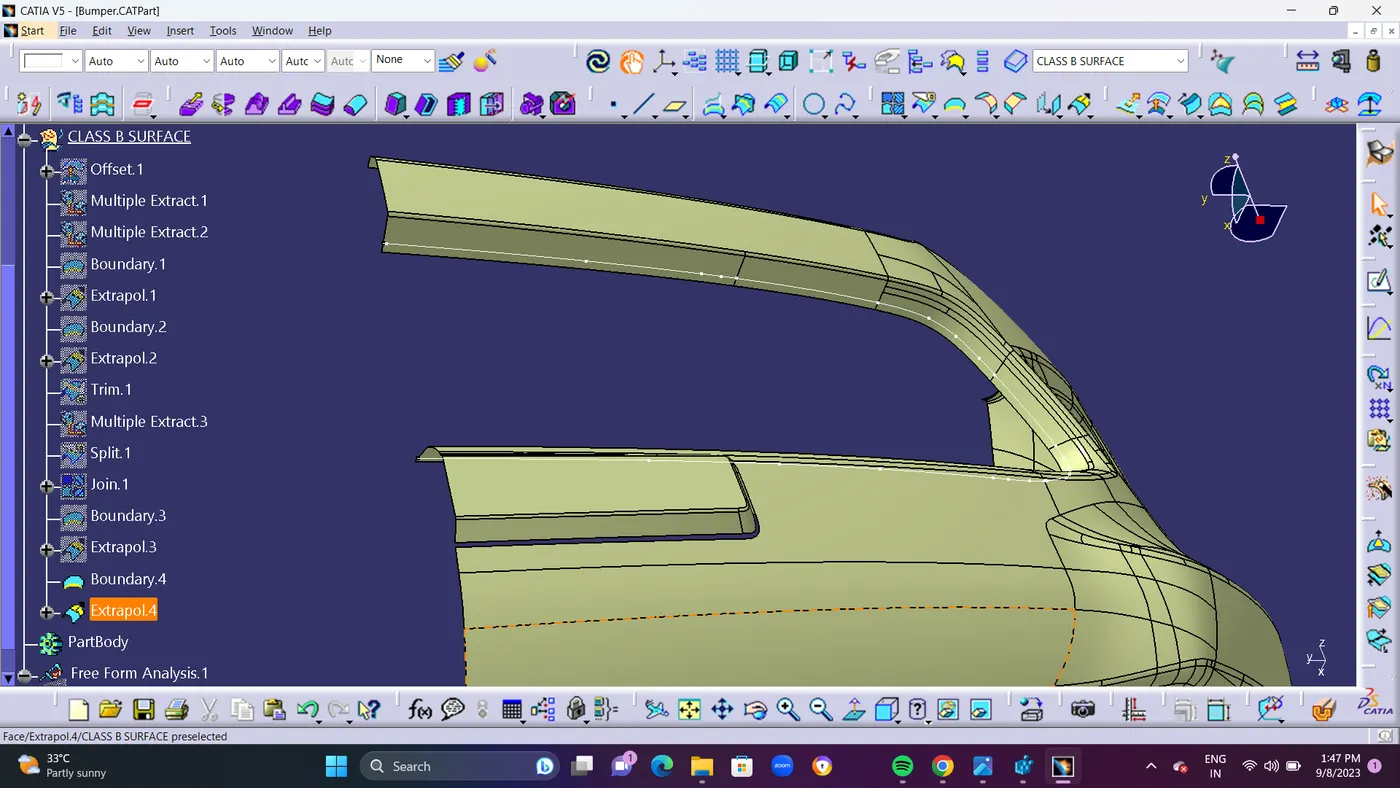
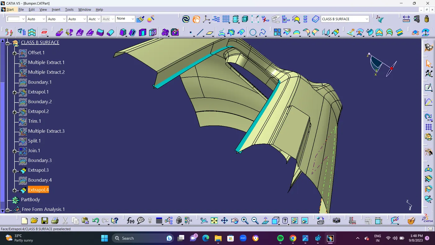
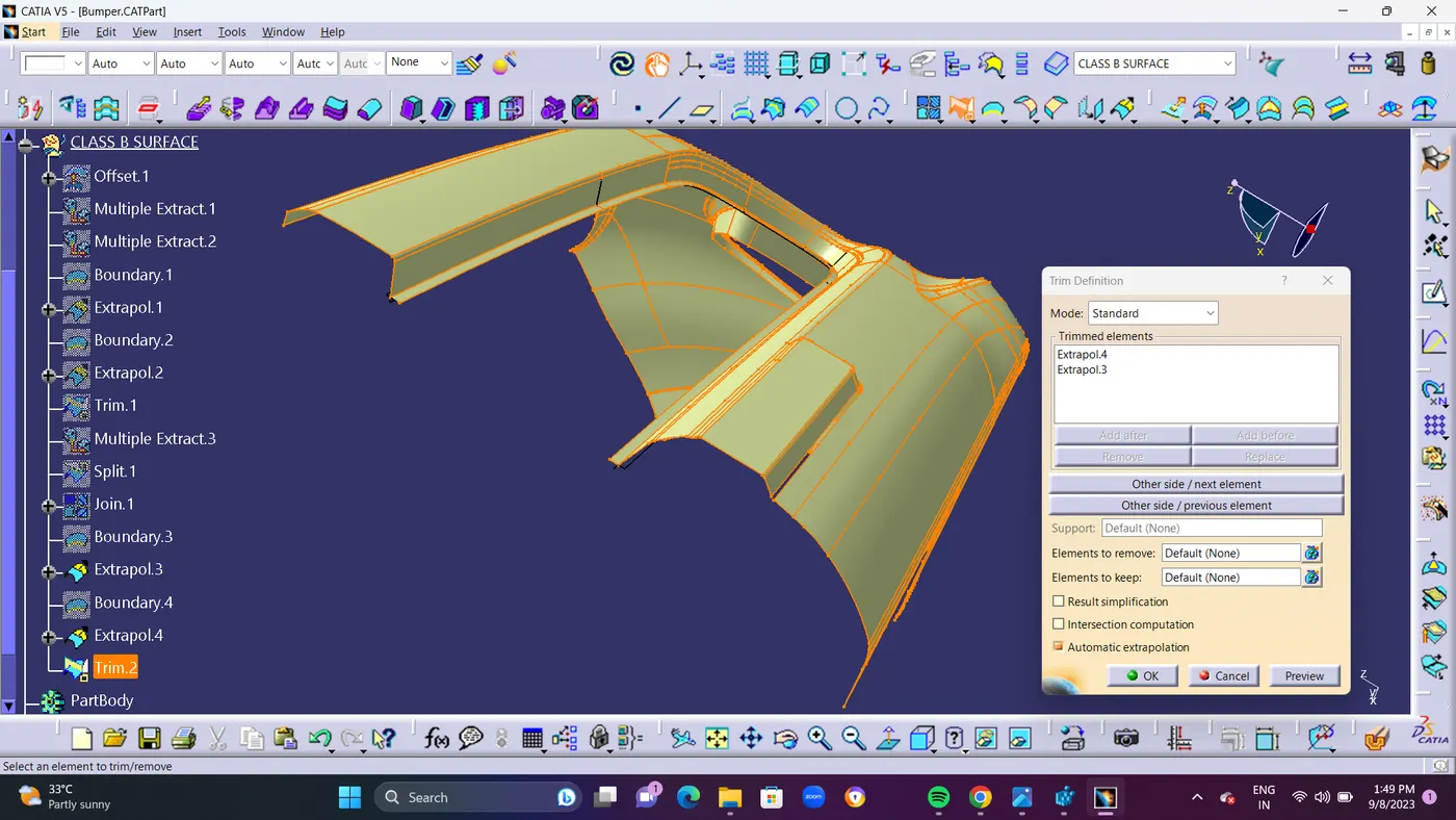
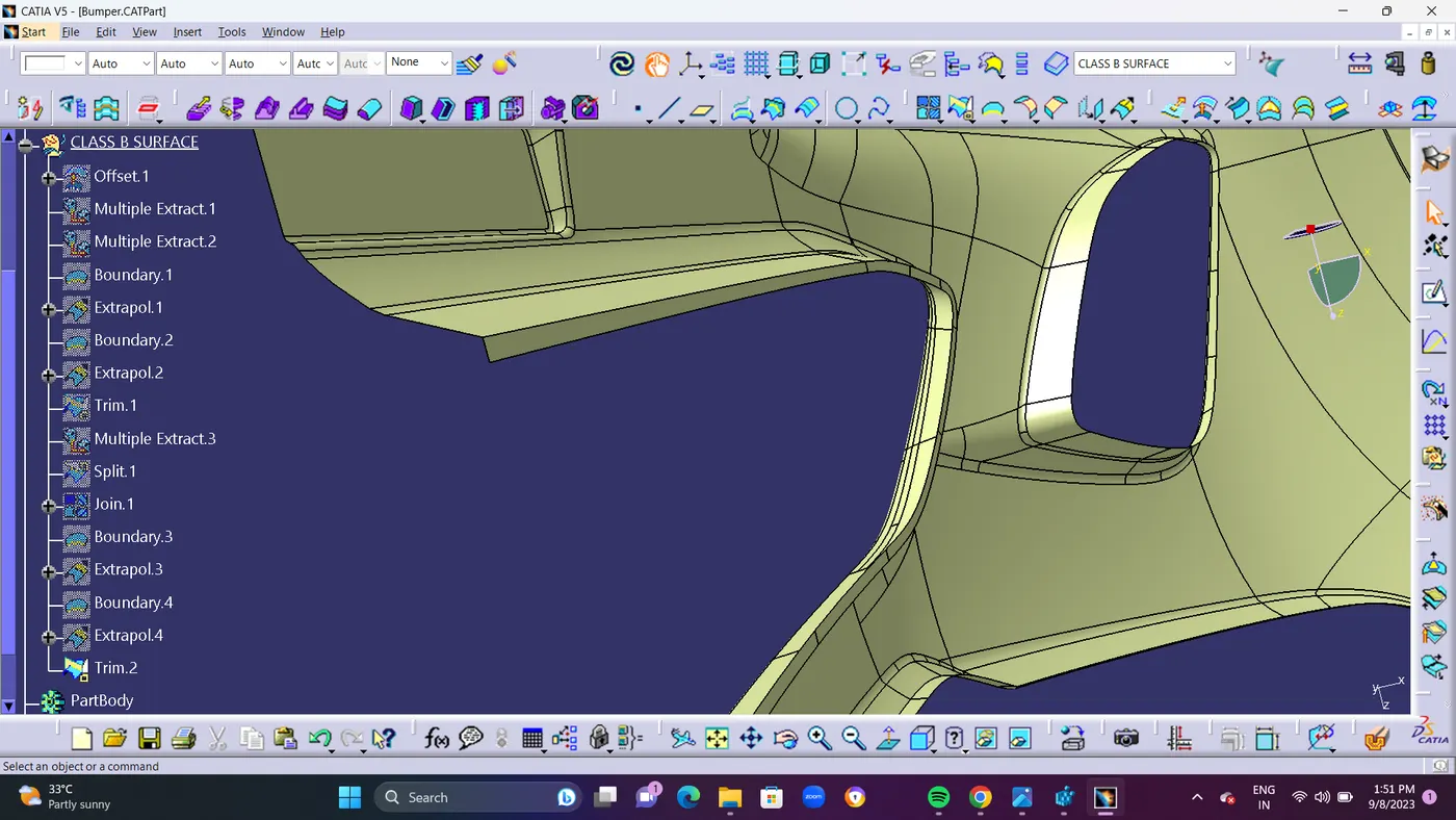
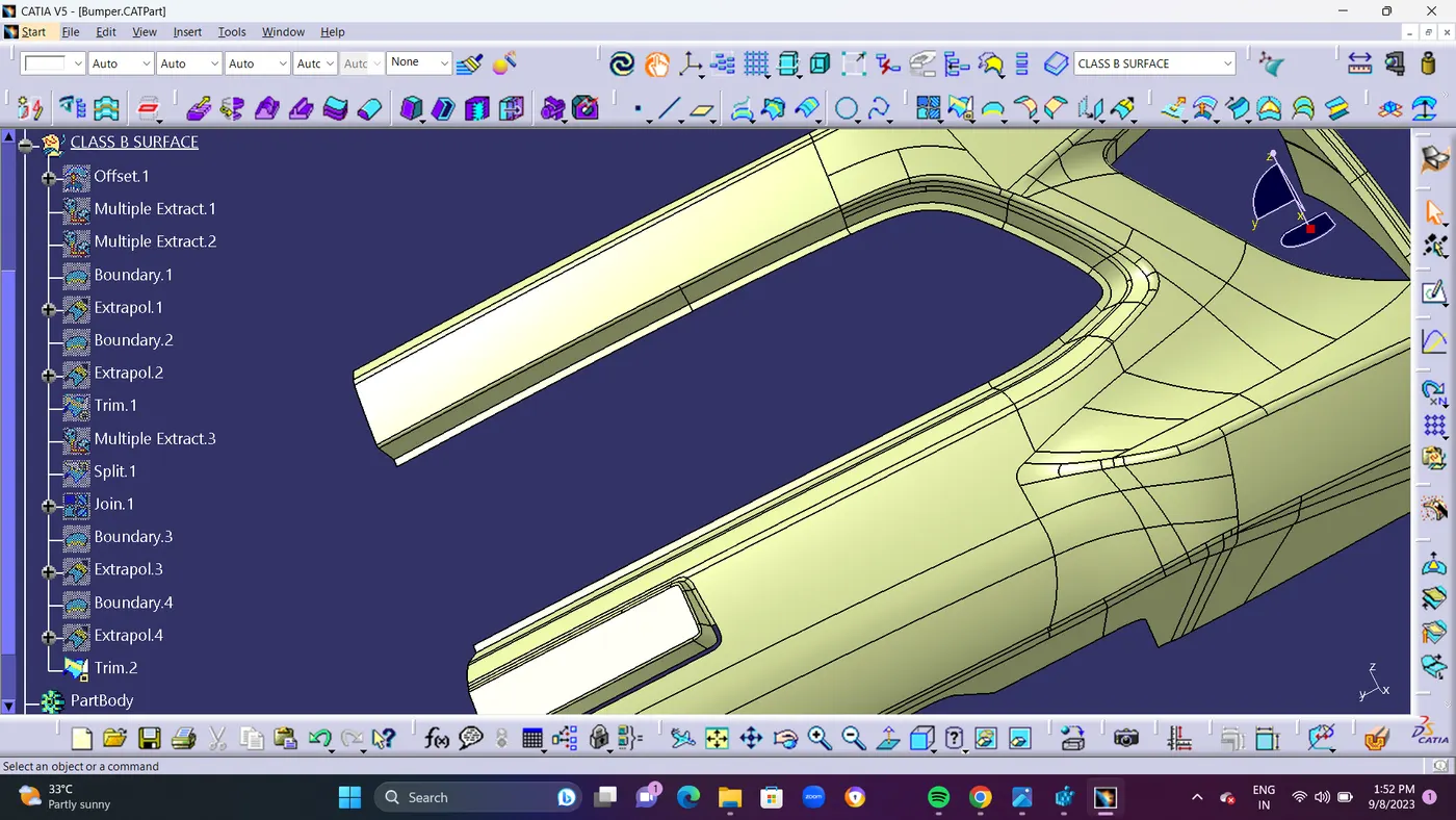
- STEP 4 : Now we are going to solve the 3rd Surface Patch in Bumper.Use JOIN Command to remove the lower Fillet areas by using SUB-ELEMENTS to remove option and Remove the Check Connectivity option in Join Command. so that all fillets which you want to be removed will be disapear.
- By using MULTIPLE EXTRACT Extract Join.2\face.55 and Join.2\face.56
- After Extract Done use join Command to remove the upper fillet area by using the option called SUB -ELEMENTS to be remove and also hide the check connectivity option from join command.after removing take Multiple Extract command of join.3\face.63 and join.3\face.64 and extract it.
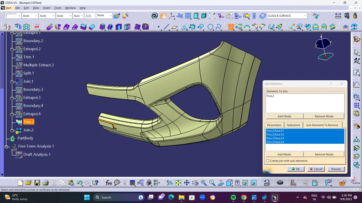
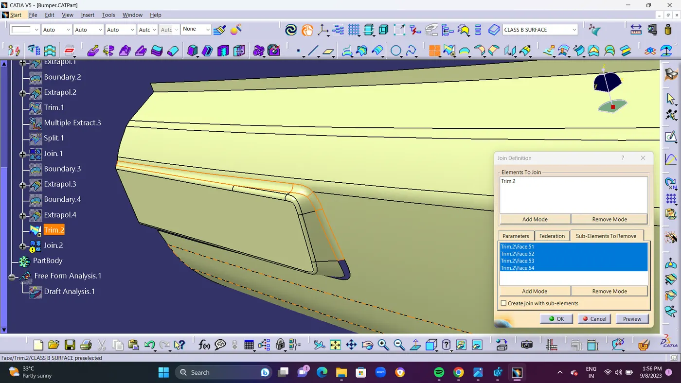
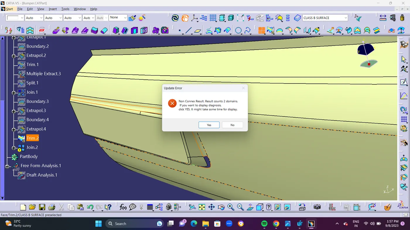
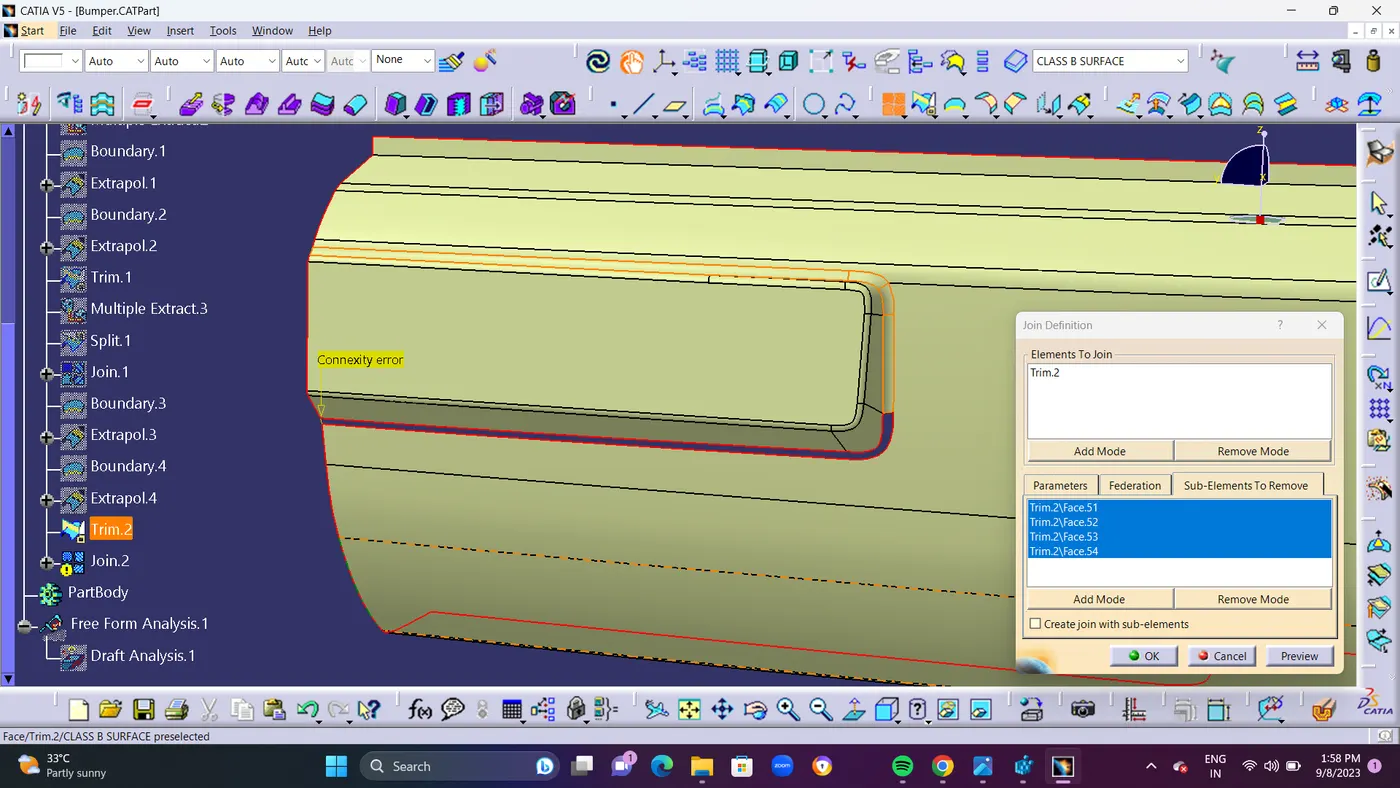
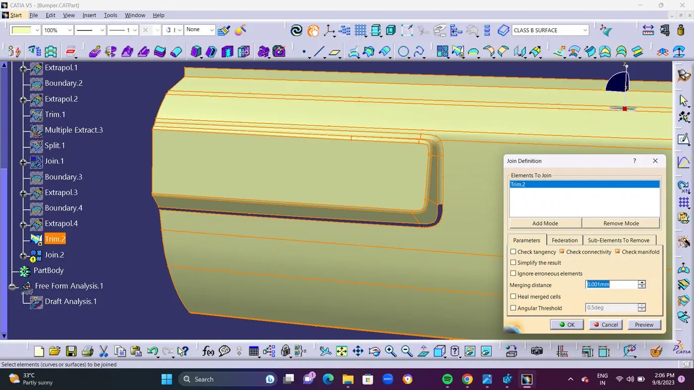
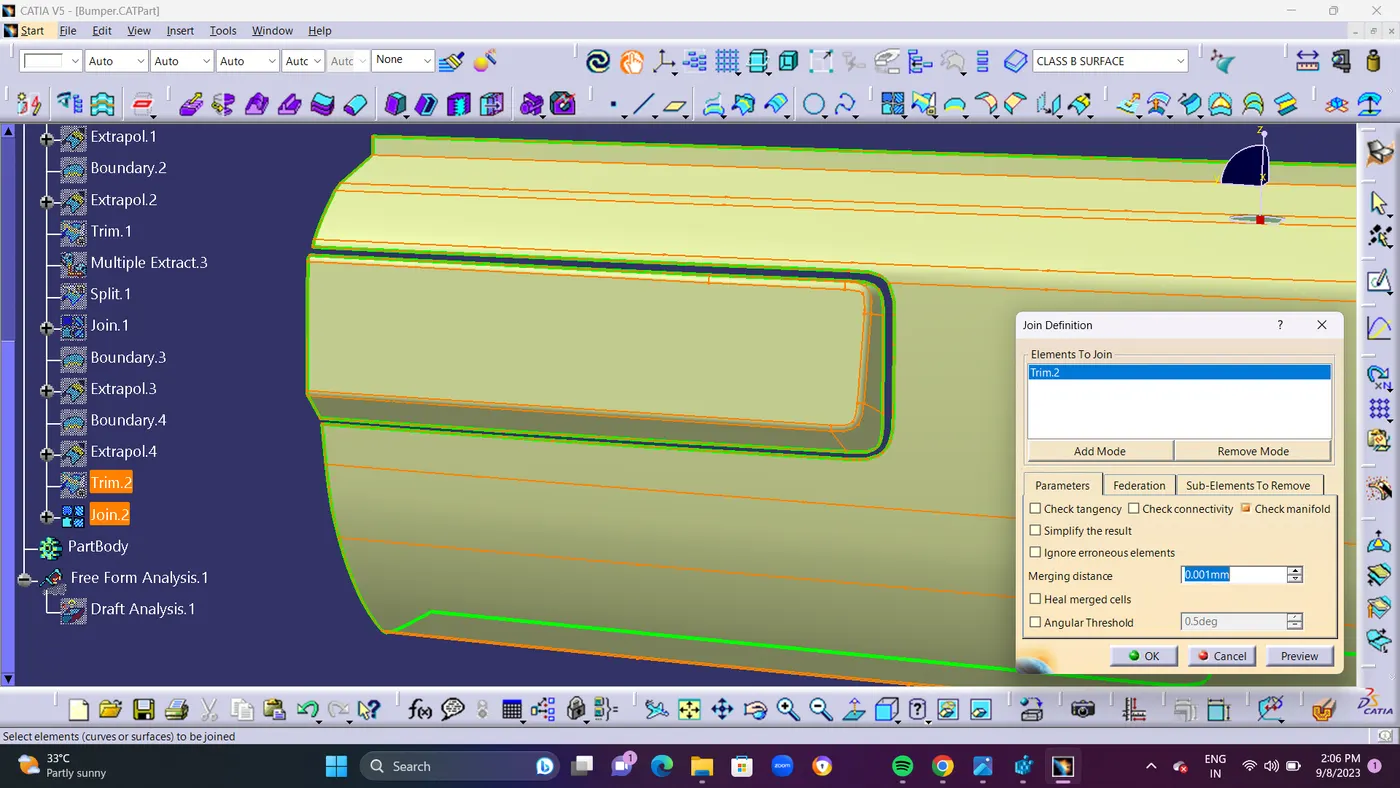
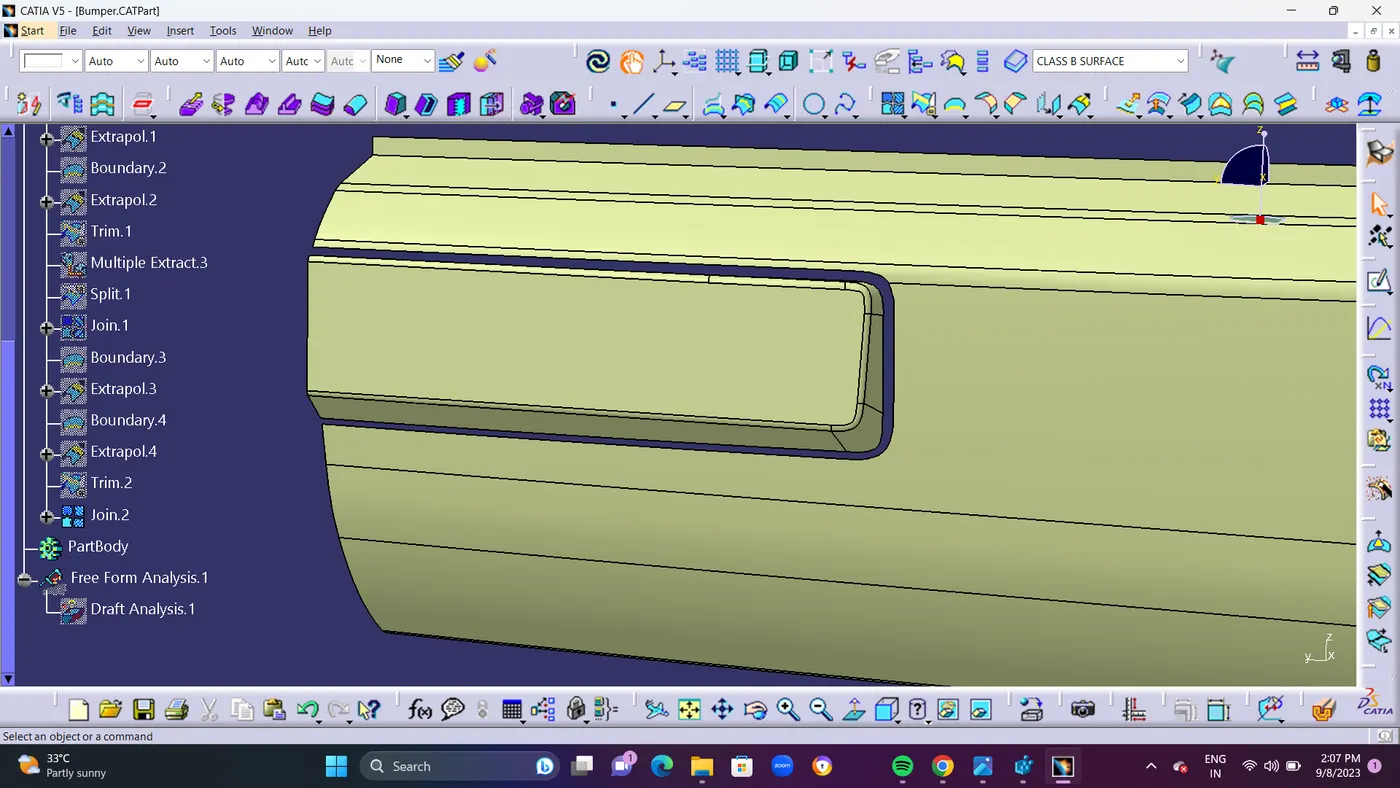
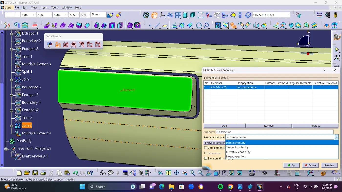
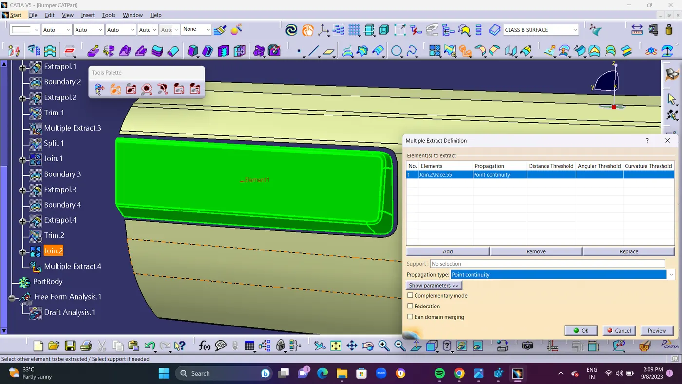
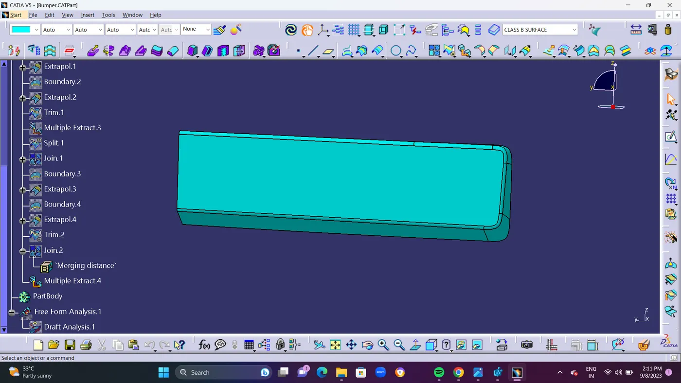
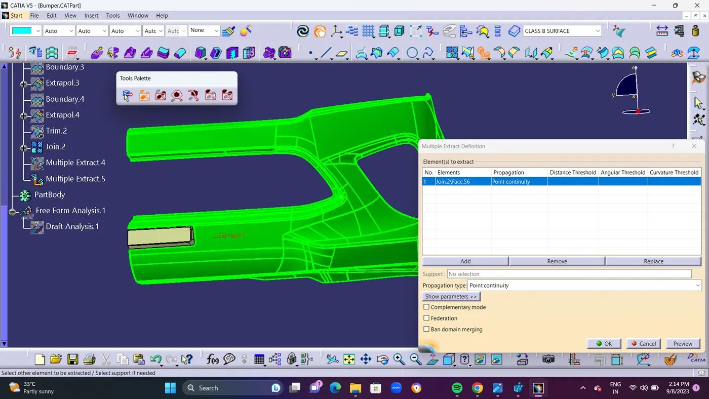
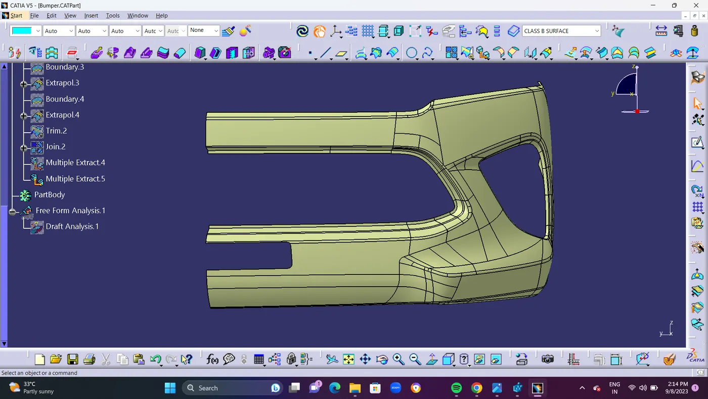
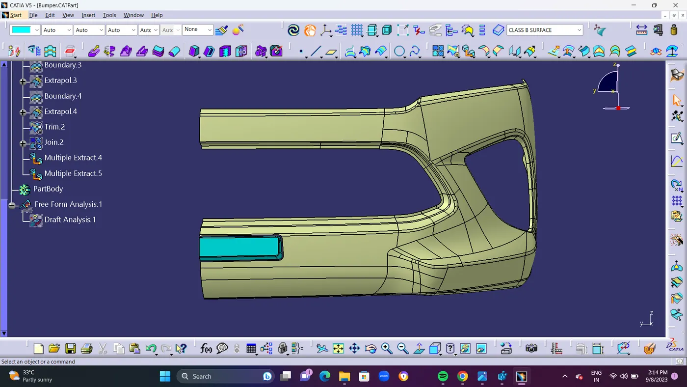
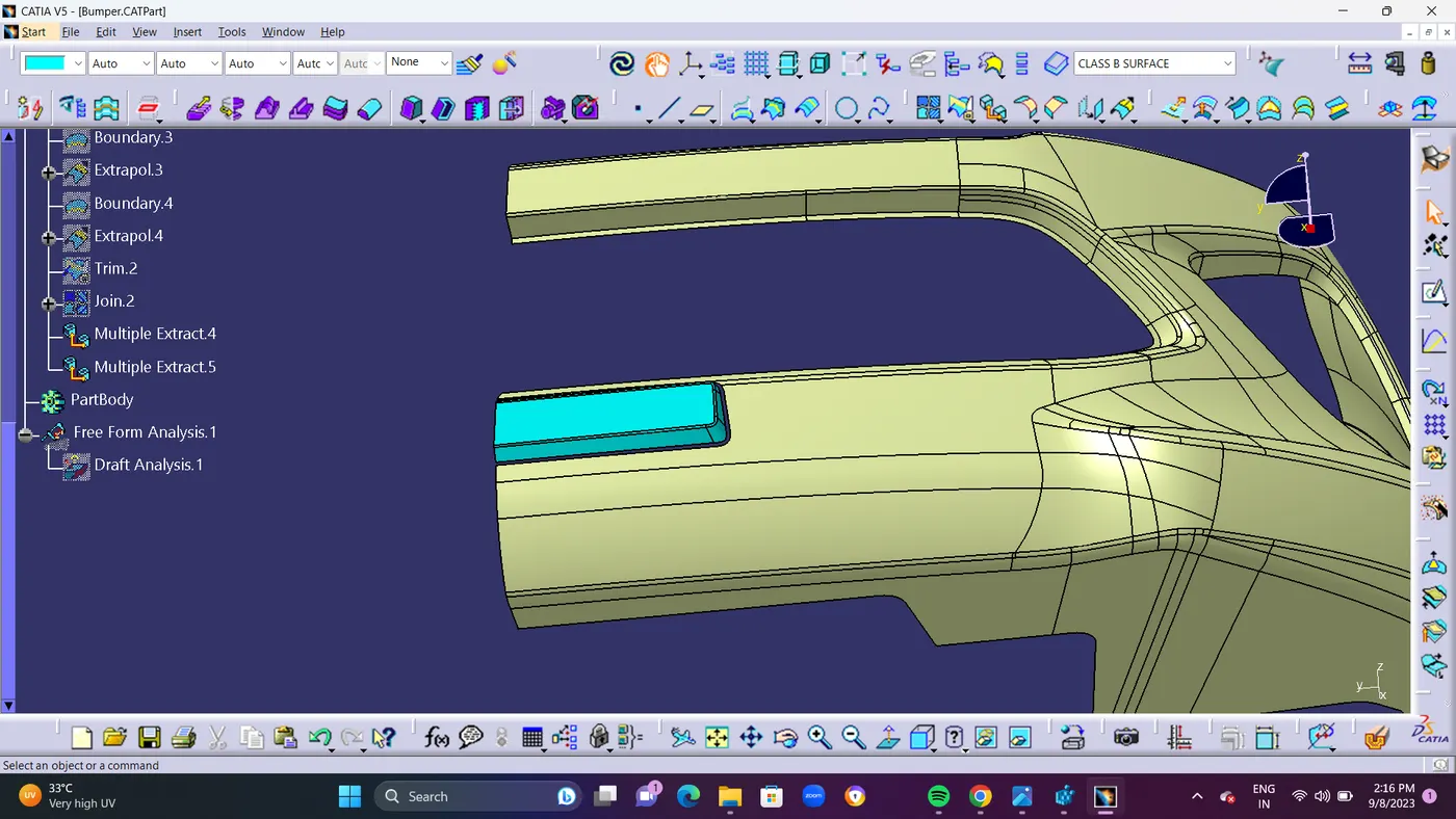
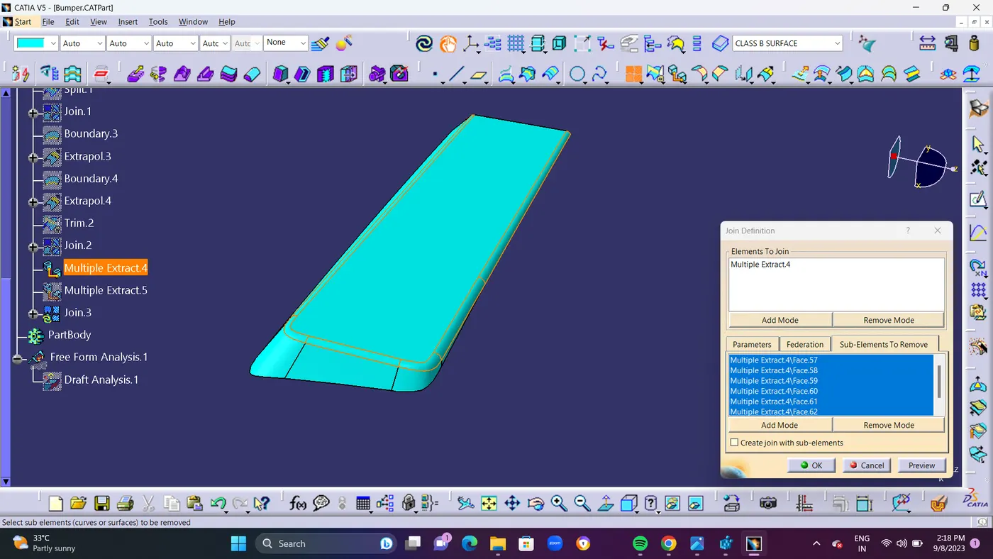
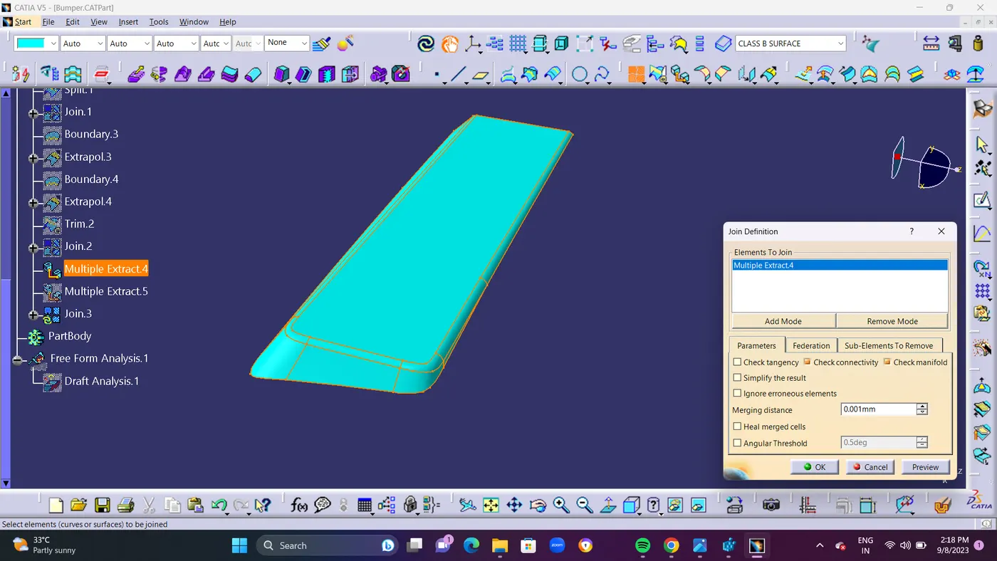
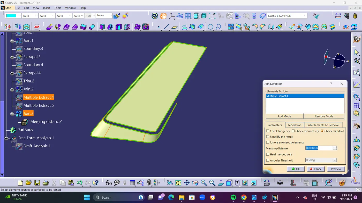
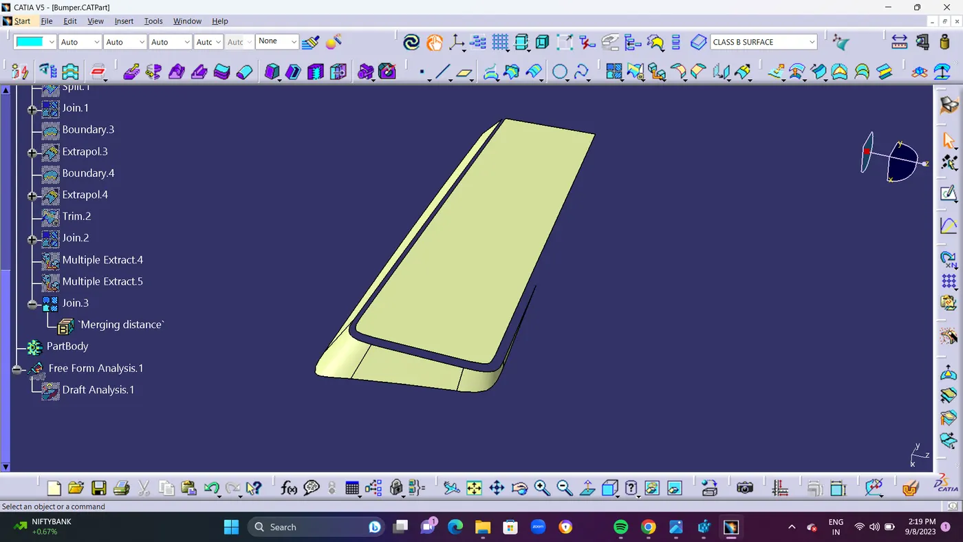
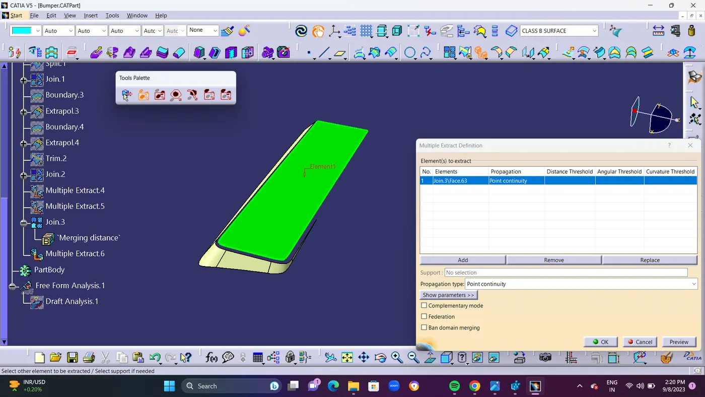
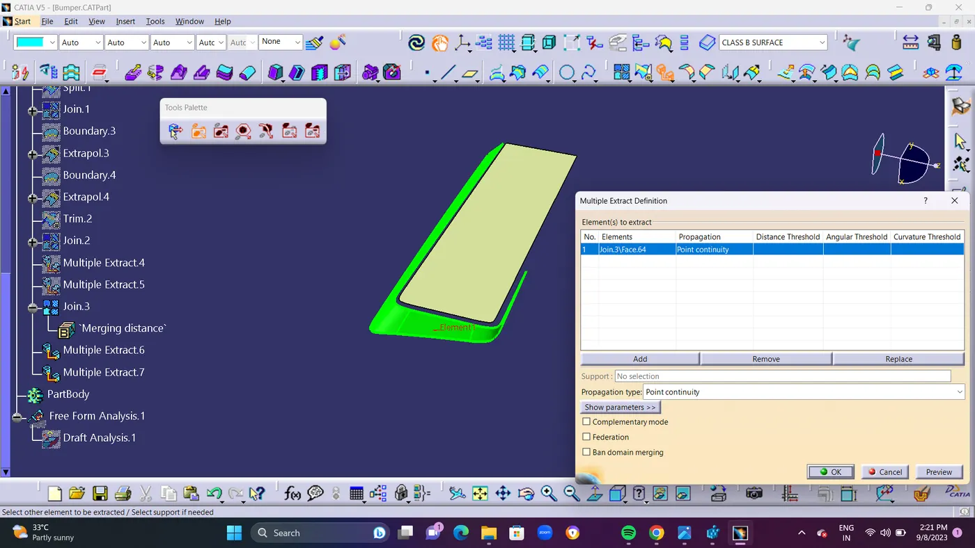
- STEP 5 : Use Boundary Command for the top surface and Extrapolate it. as shown in Below ScreenShots.Same as for Side Surface also.
- and finally TRIM the Top Surface as Extrapolate.5 with Side Surface as TRIM.3 for making as a single component.
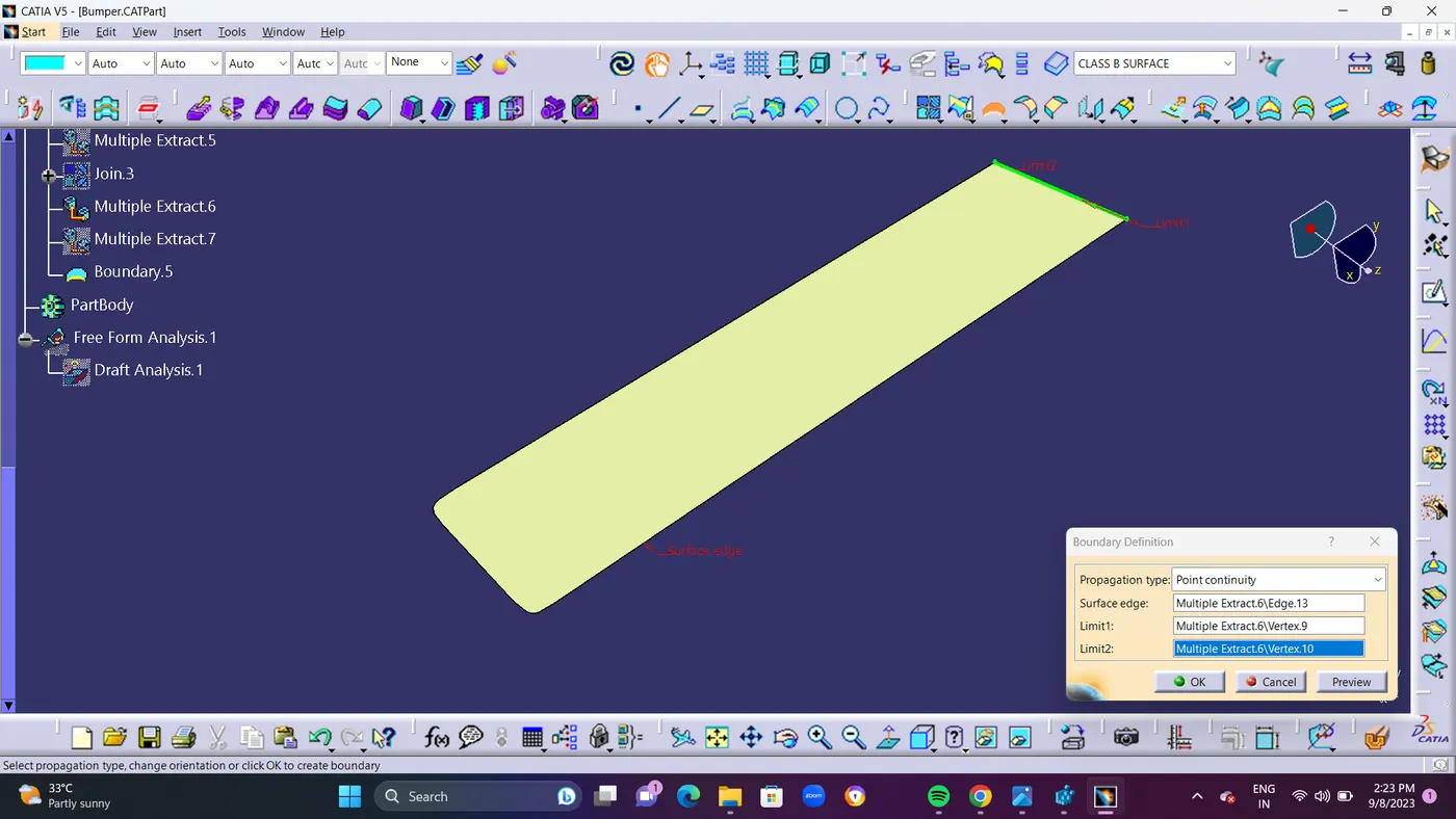
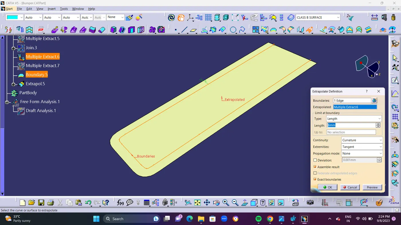
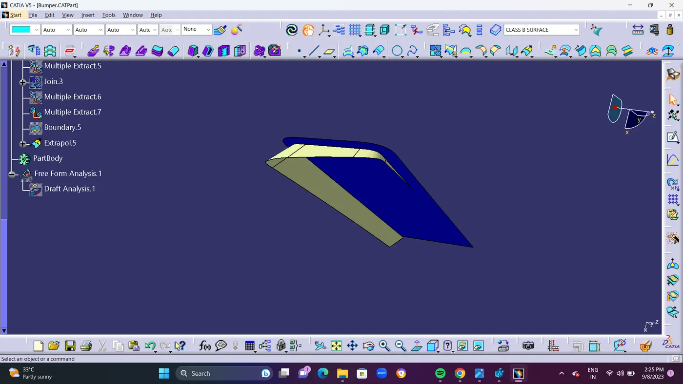
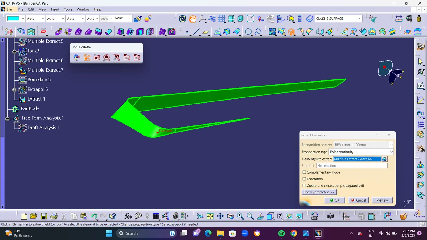
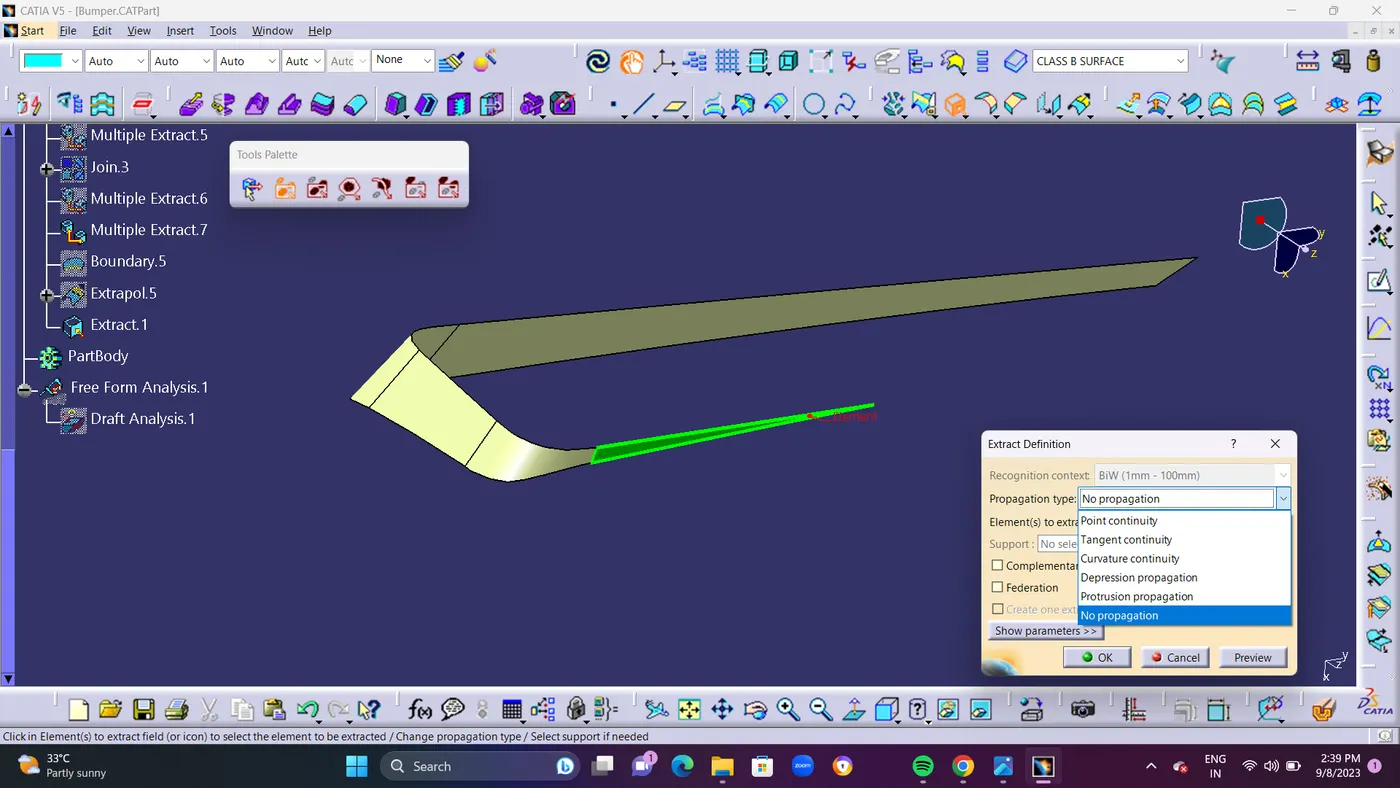
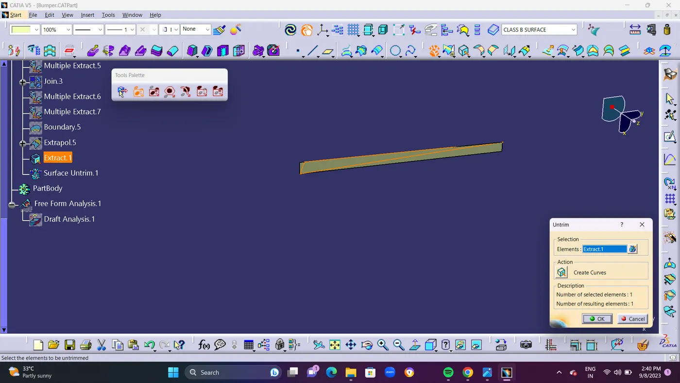
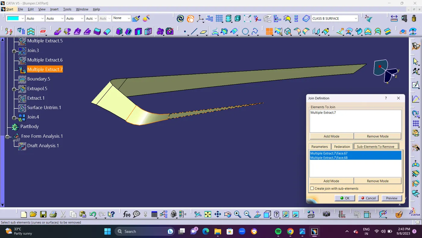
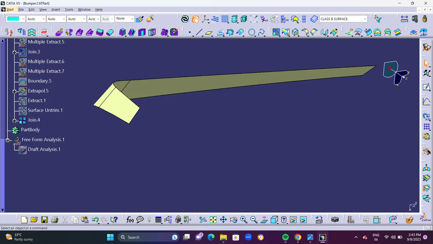
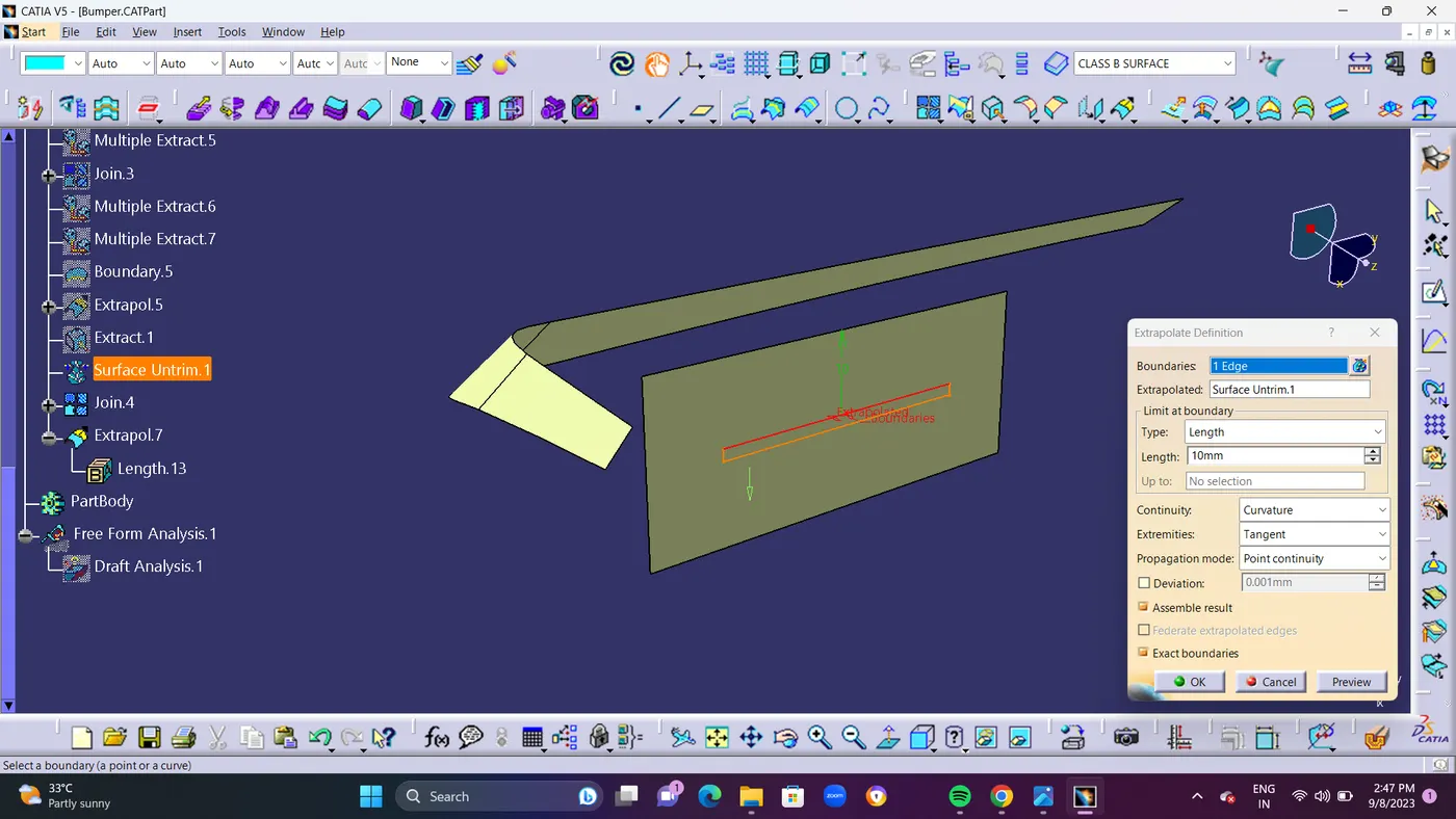
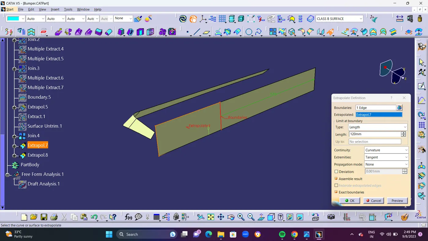
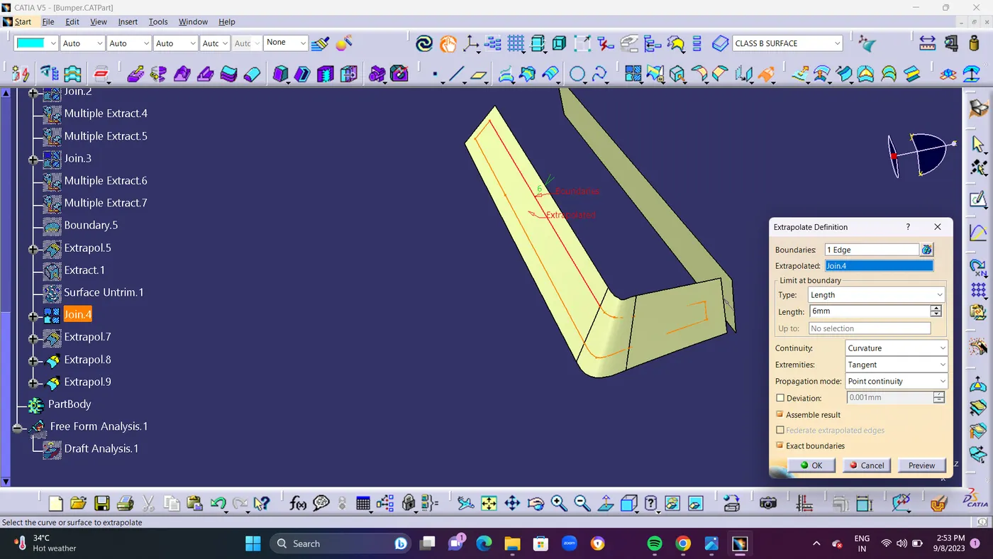
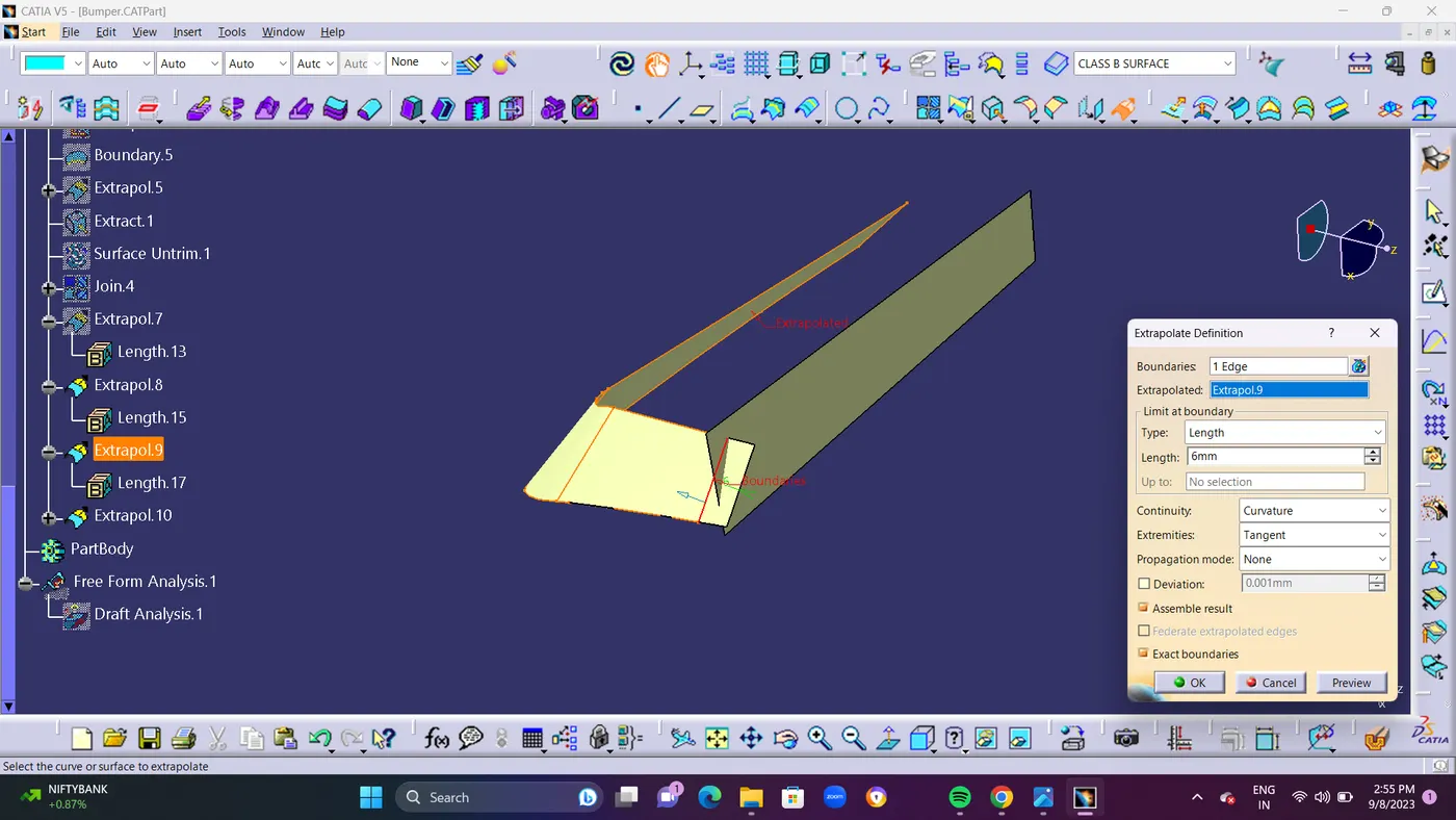
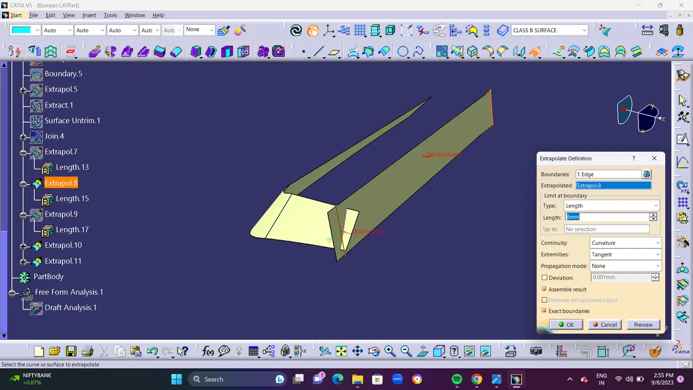
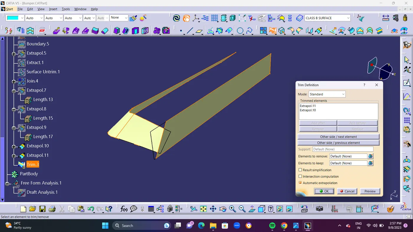
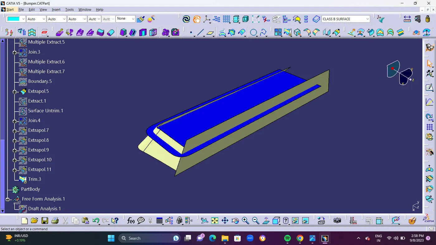
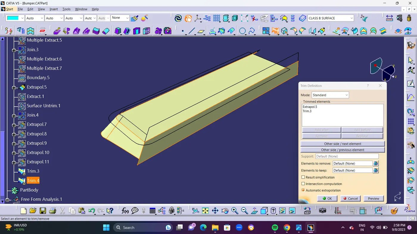
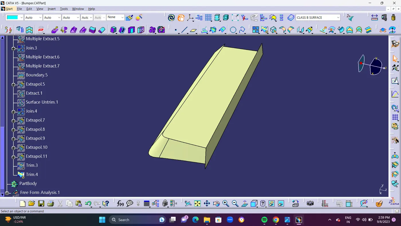
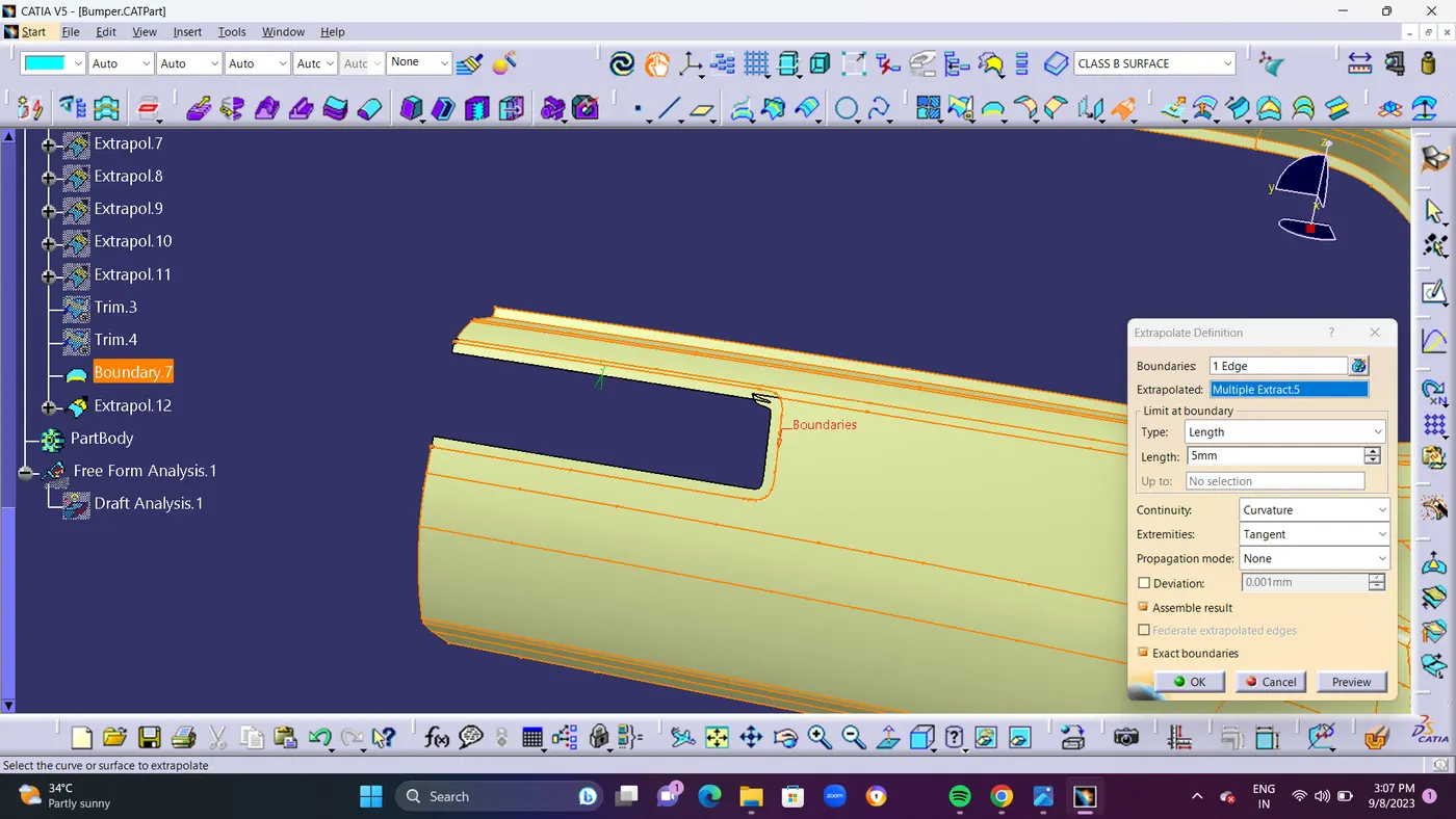
- STEP 6 : Make Boundary Line for Multiple Extract.5 and Extrapolate the Surface for 5mm.and TRIM the Extapolate.12 with Trime.4. and Finally all Surface Patches as Been Solved.
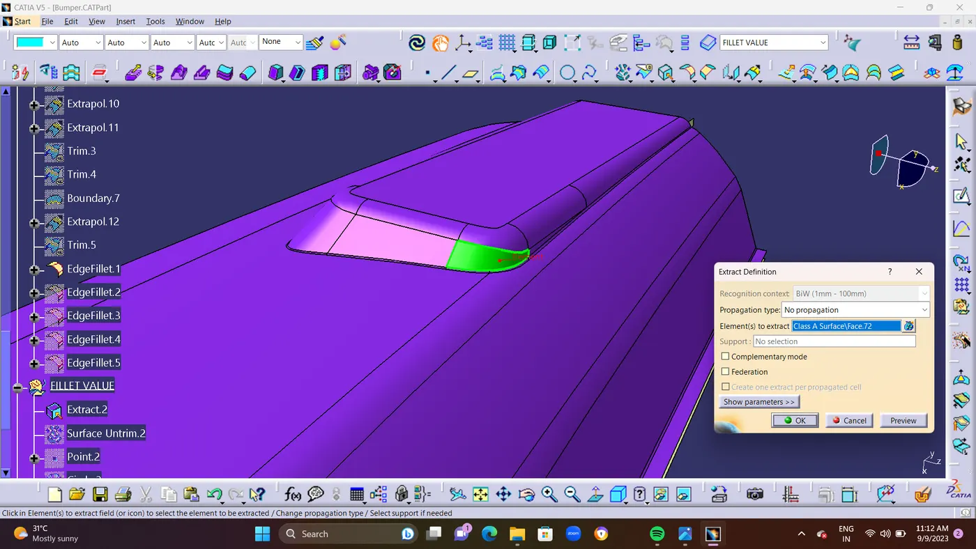
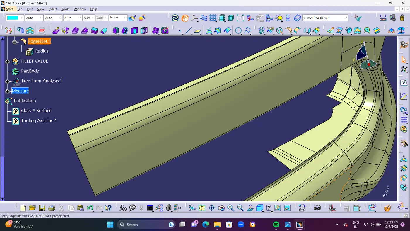
- Finally Use Edge Fillets Command For making the sharp Edges as Smooth Curve.
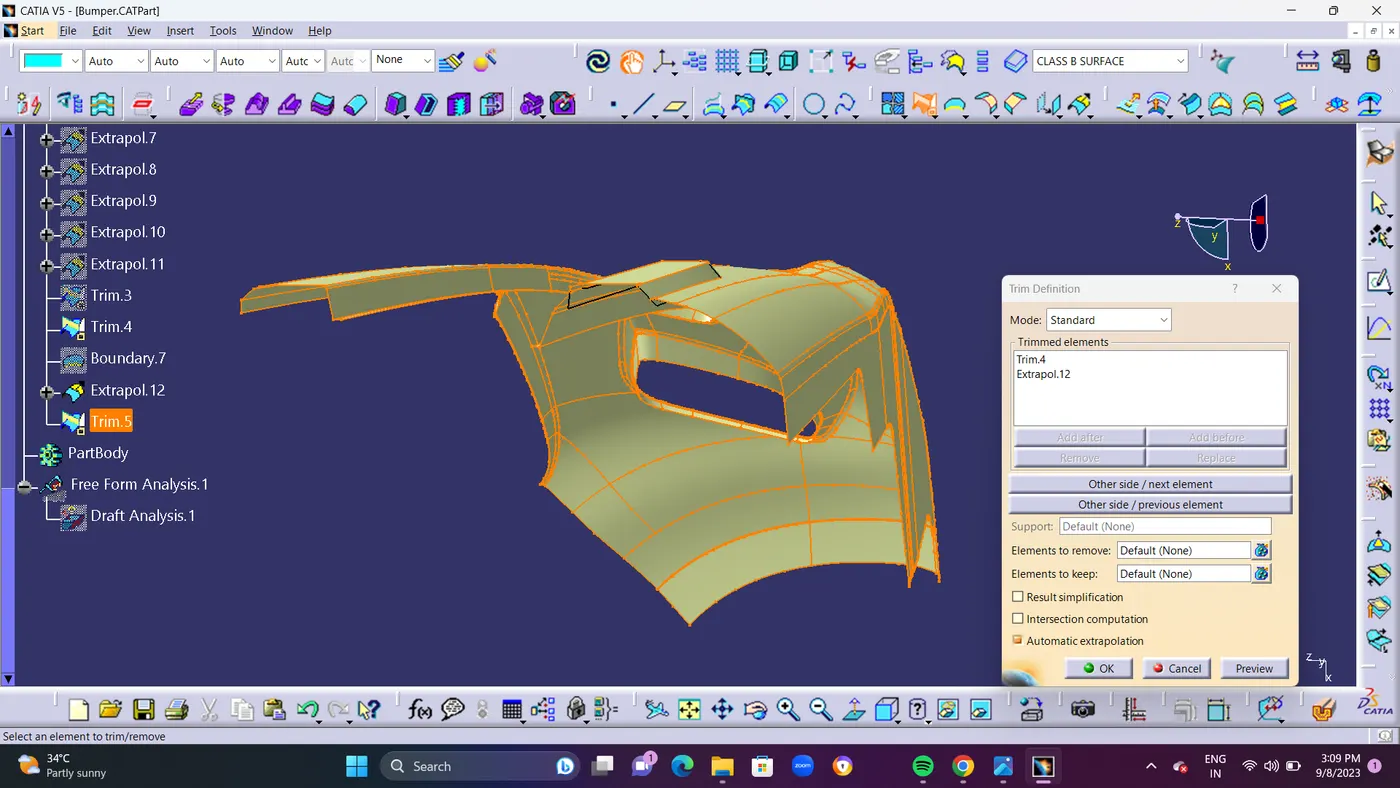
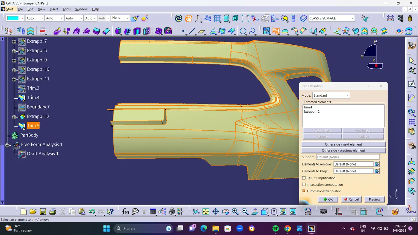
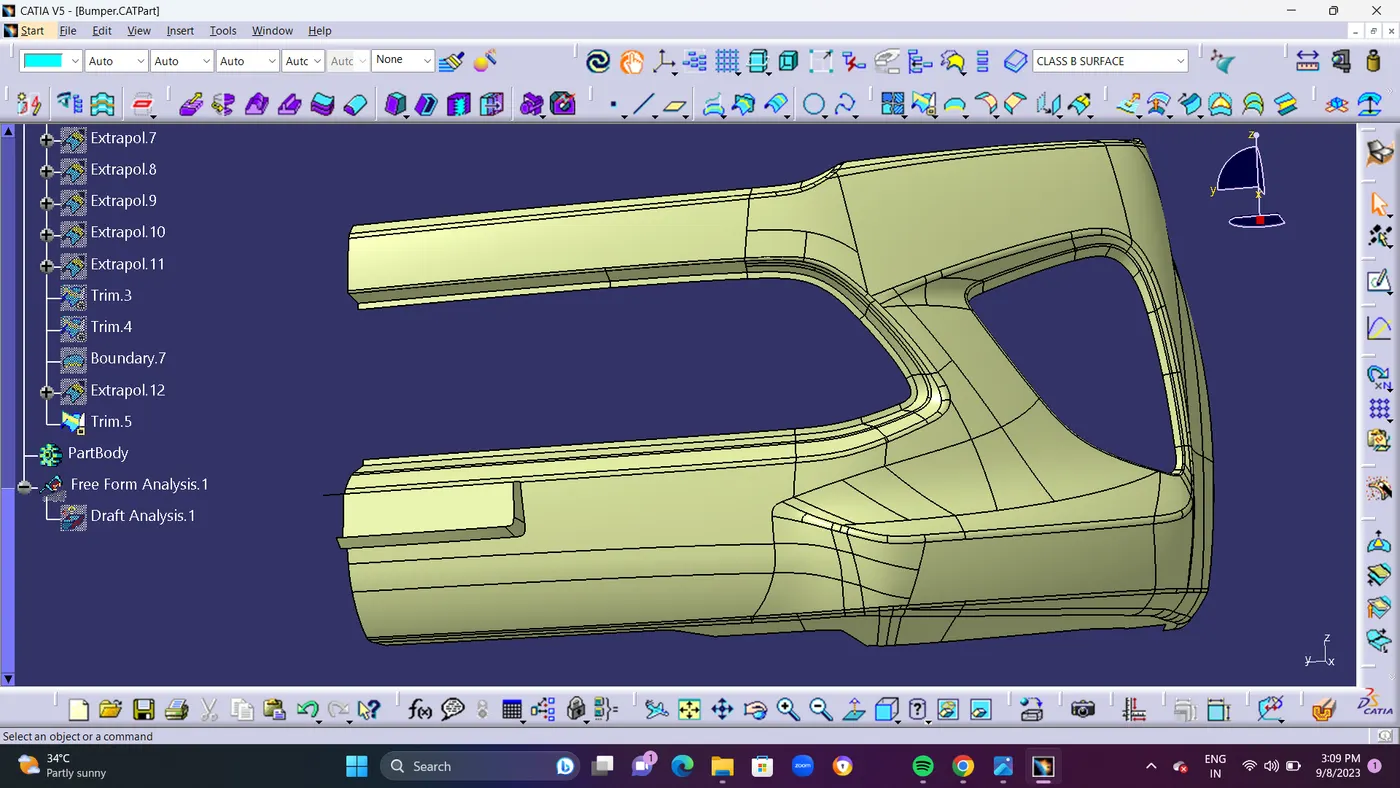
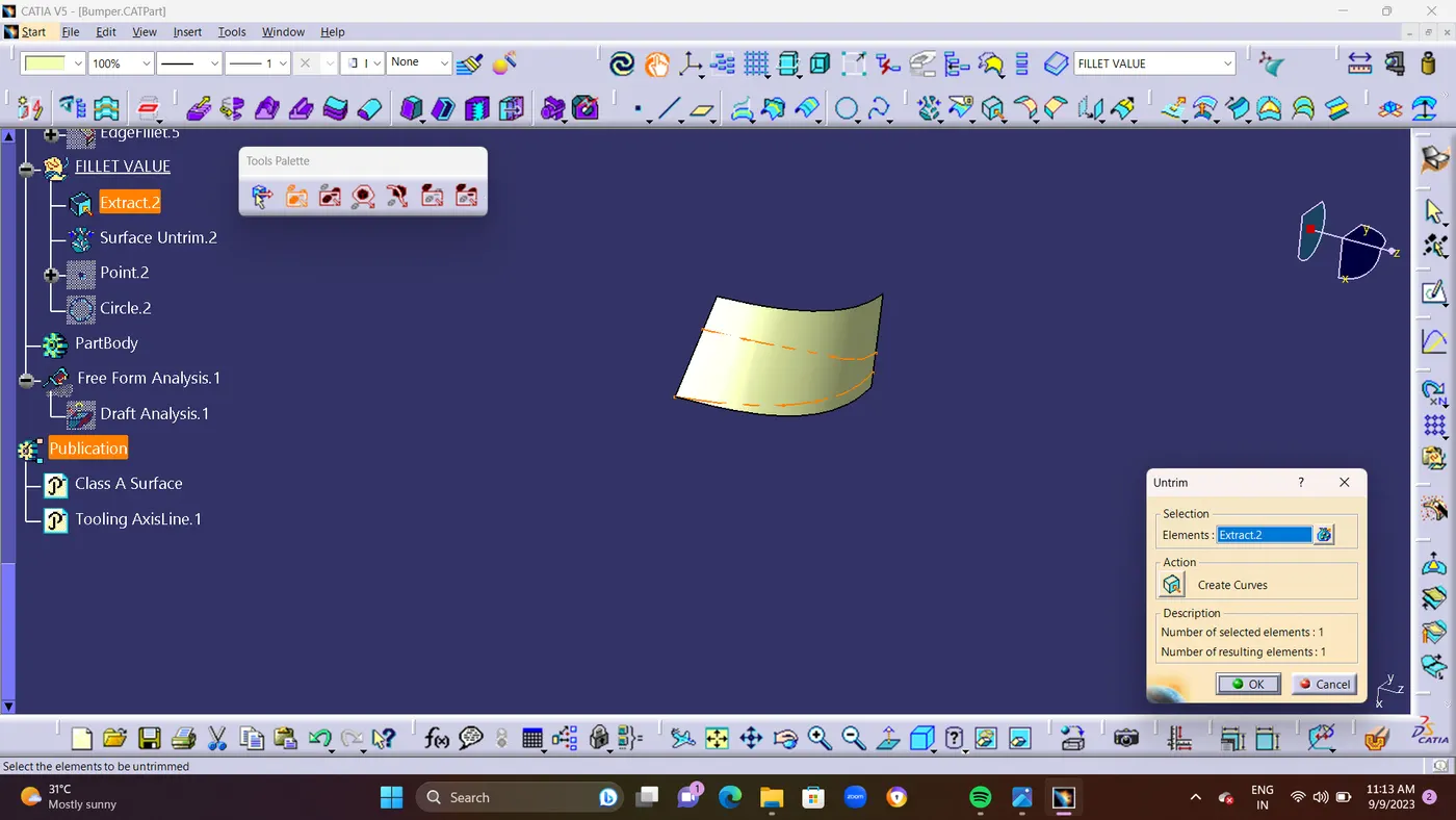
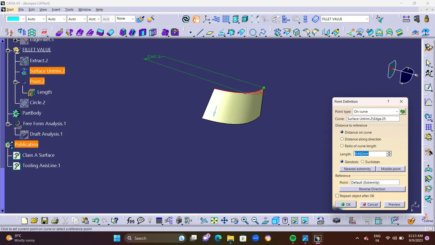
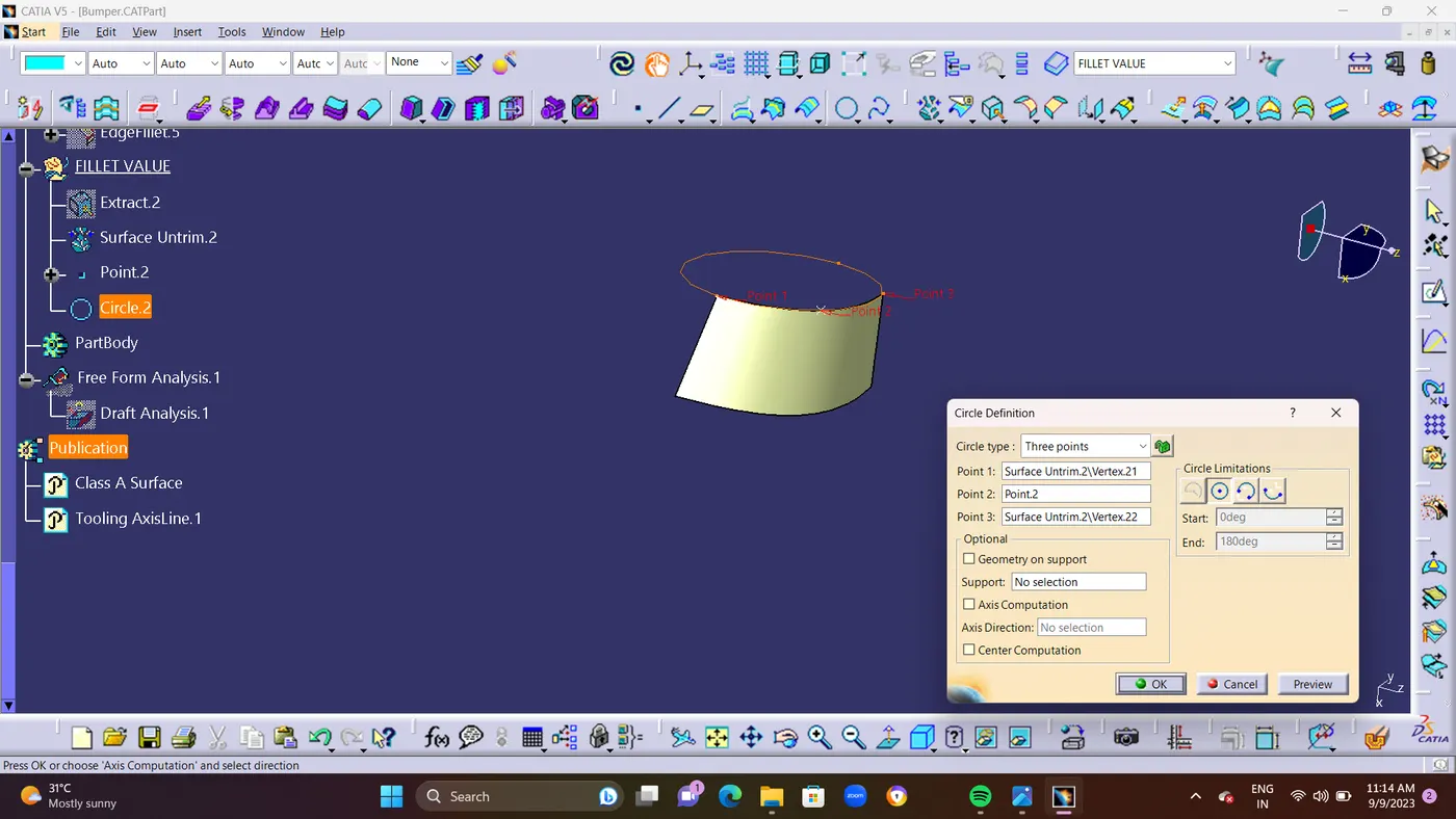
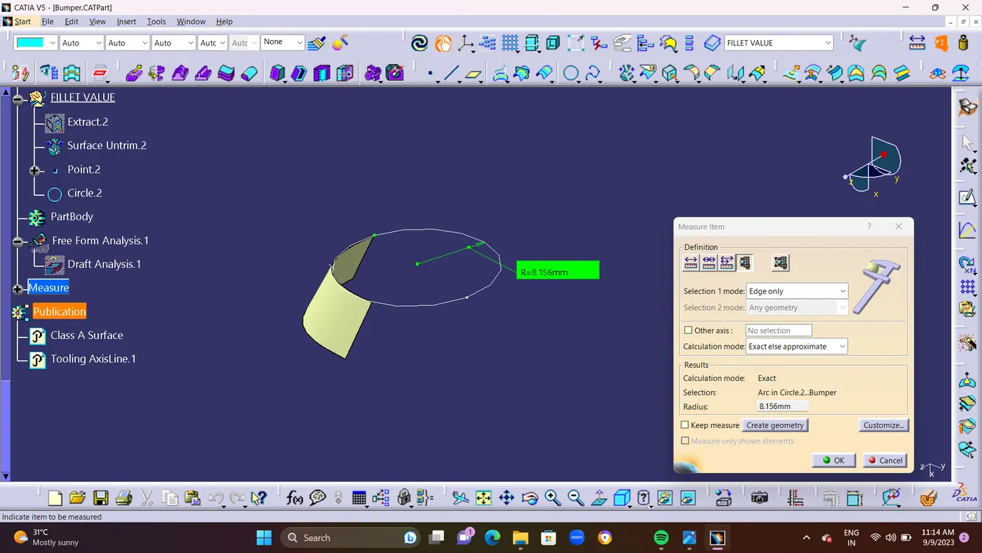
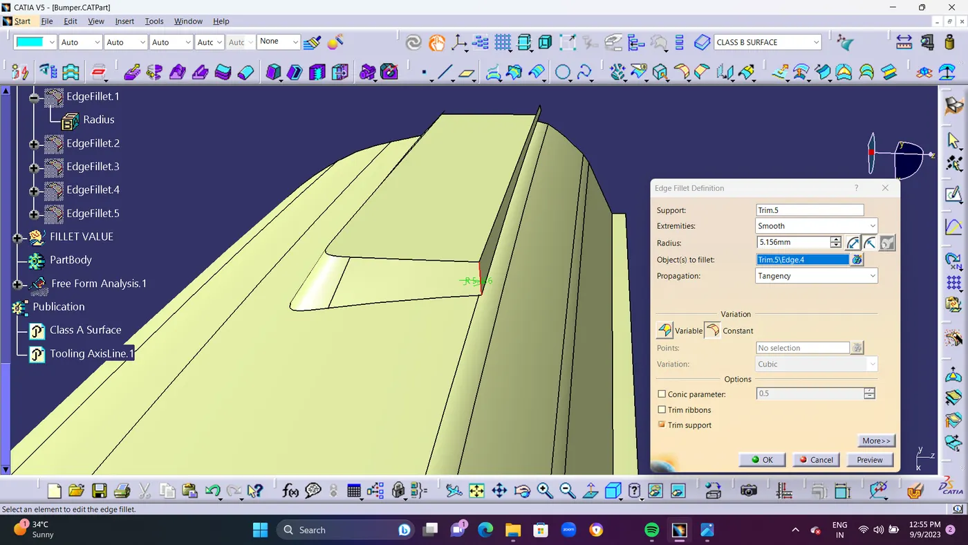
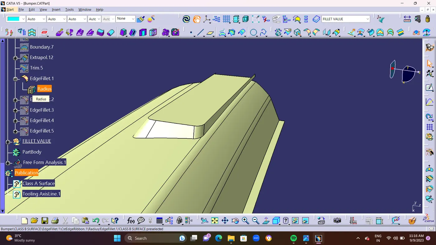
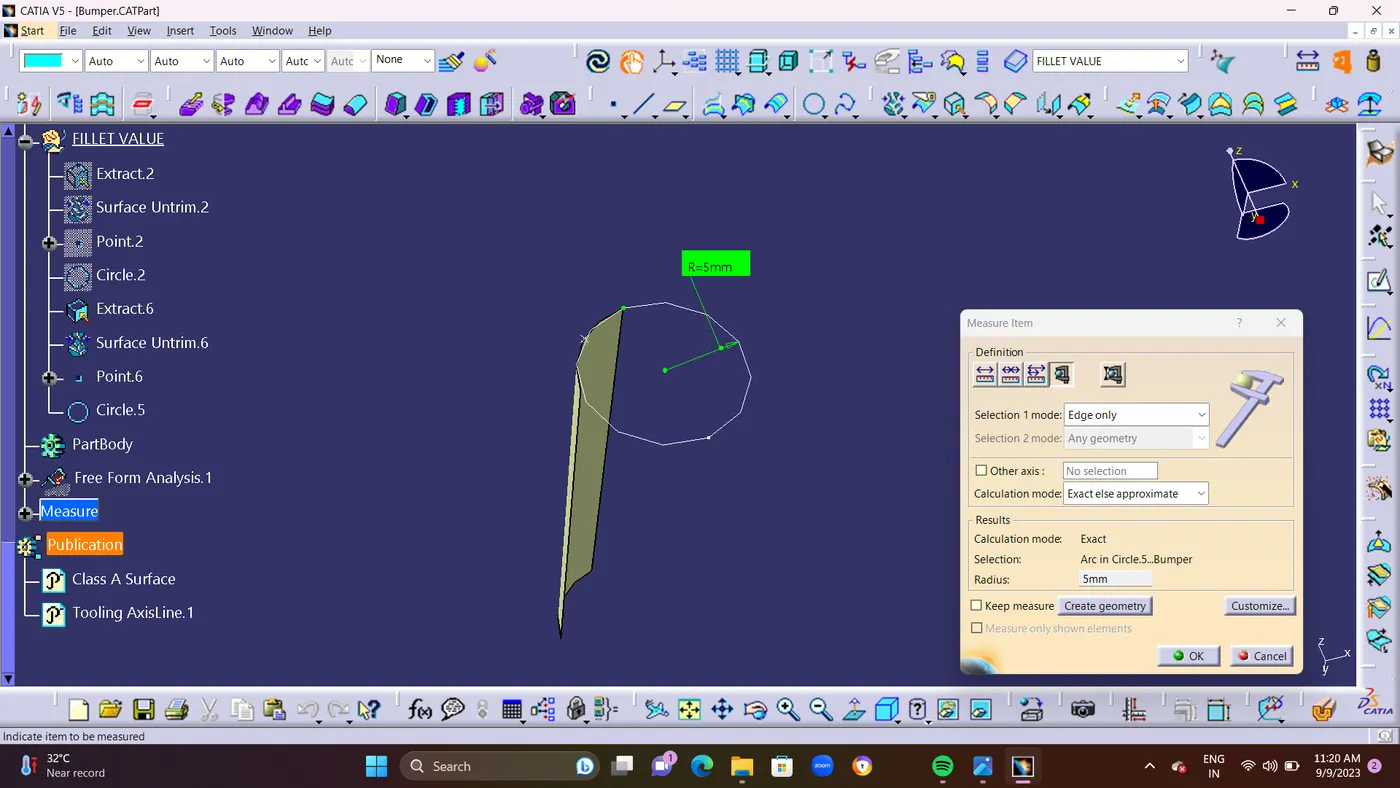
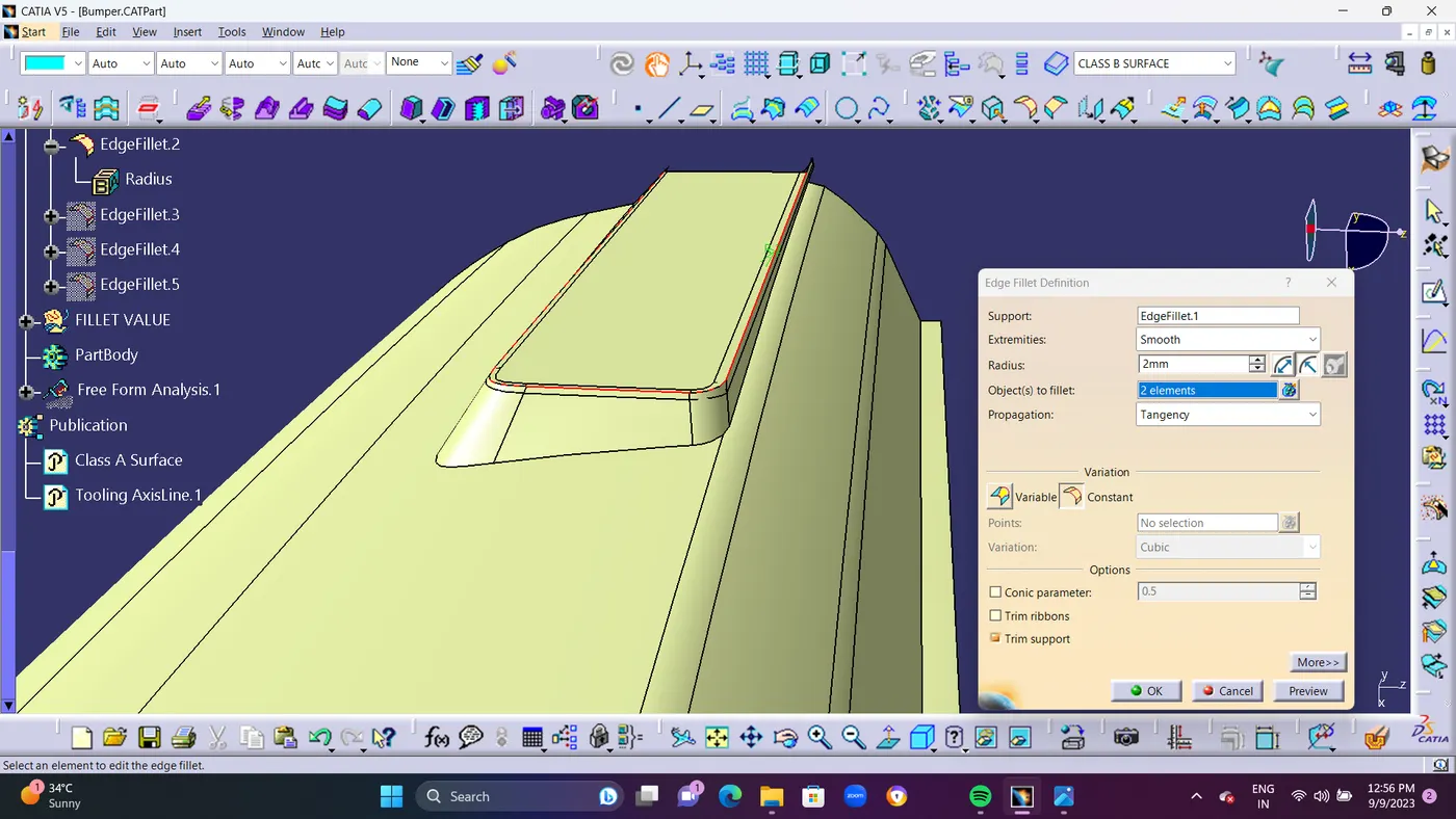
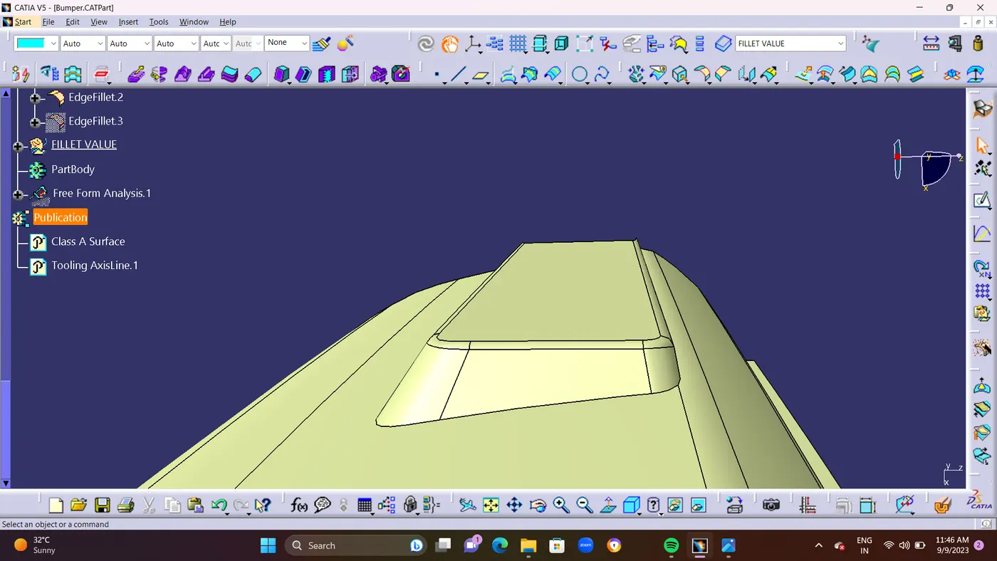
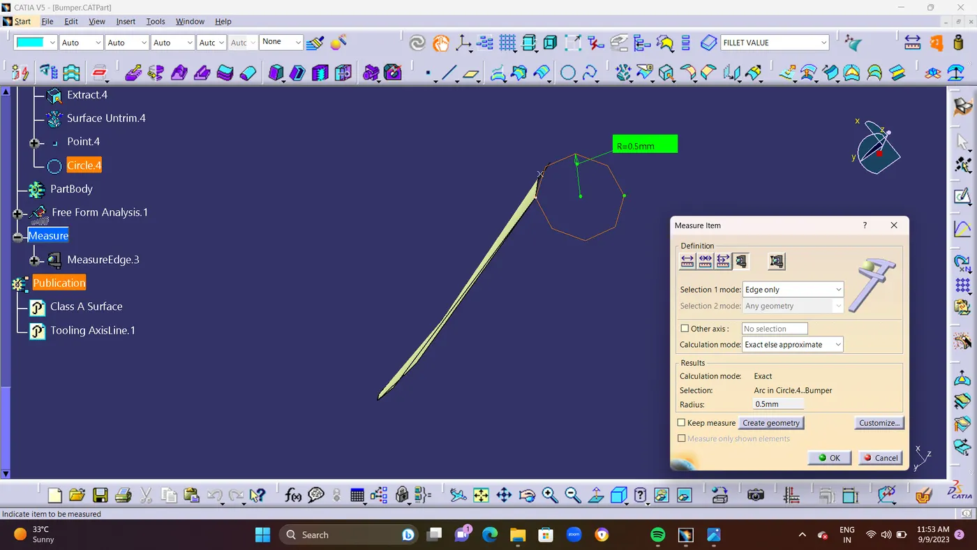
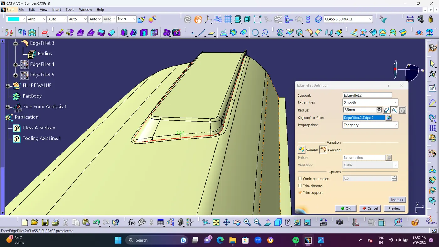
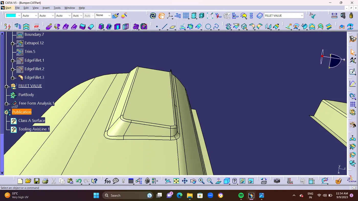
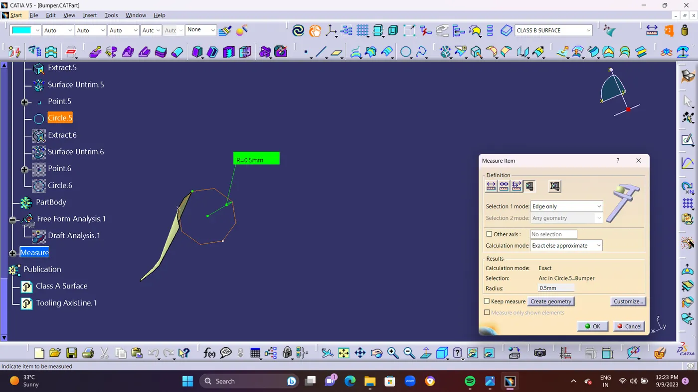
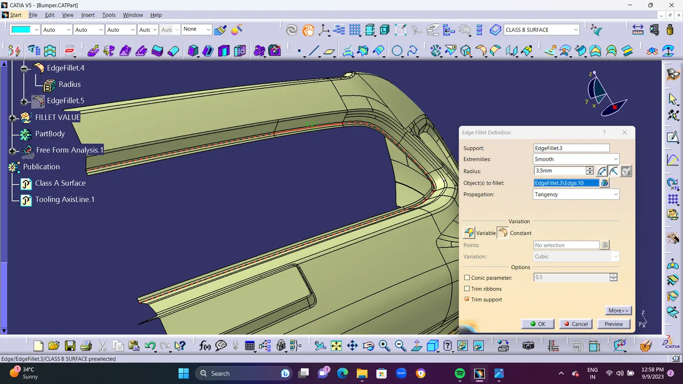
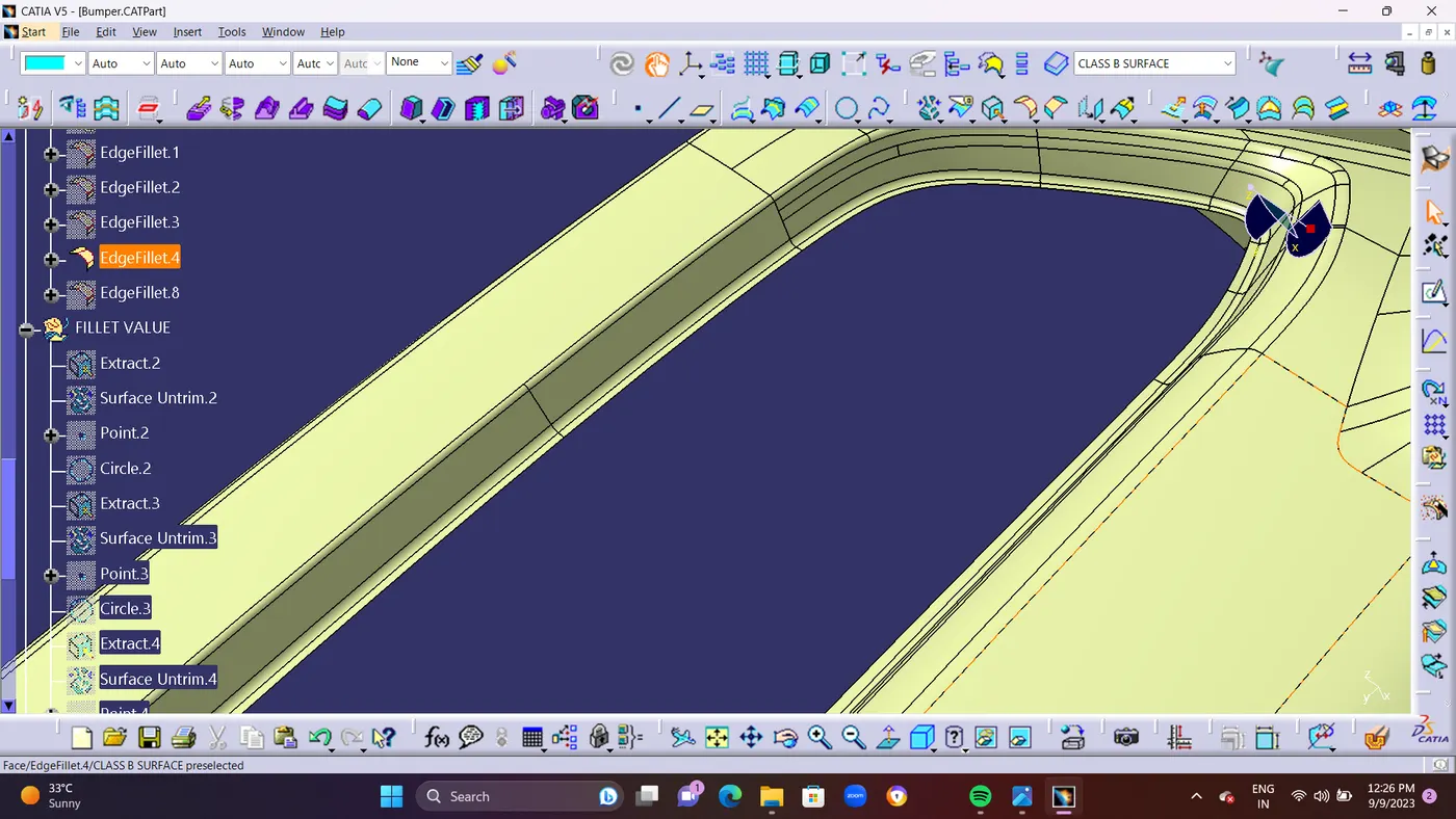
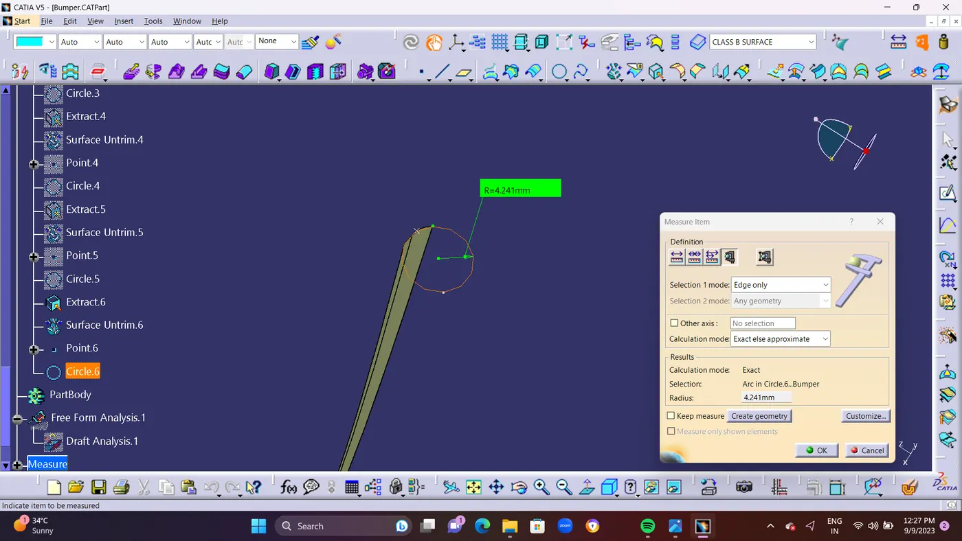
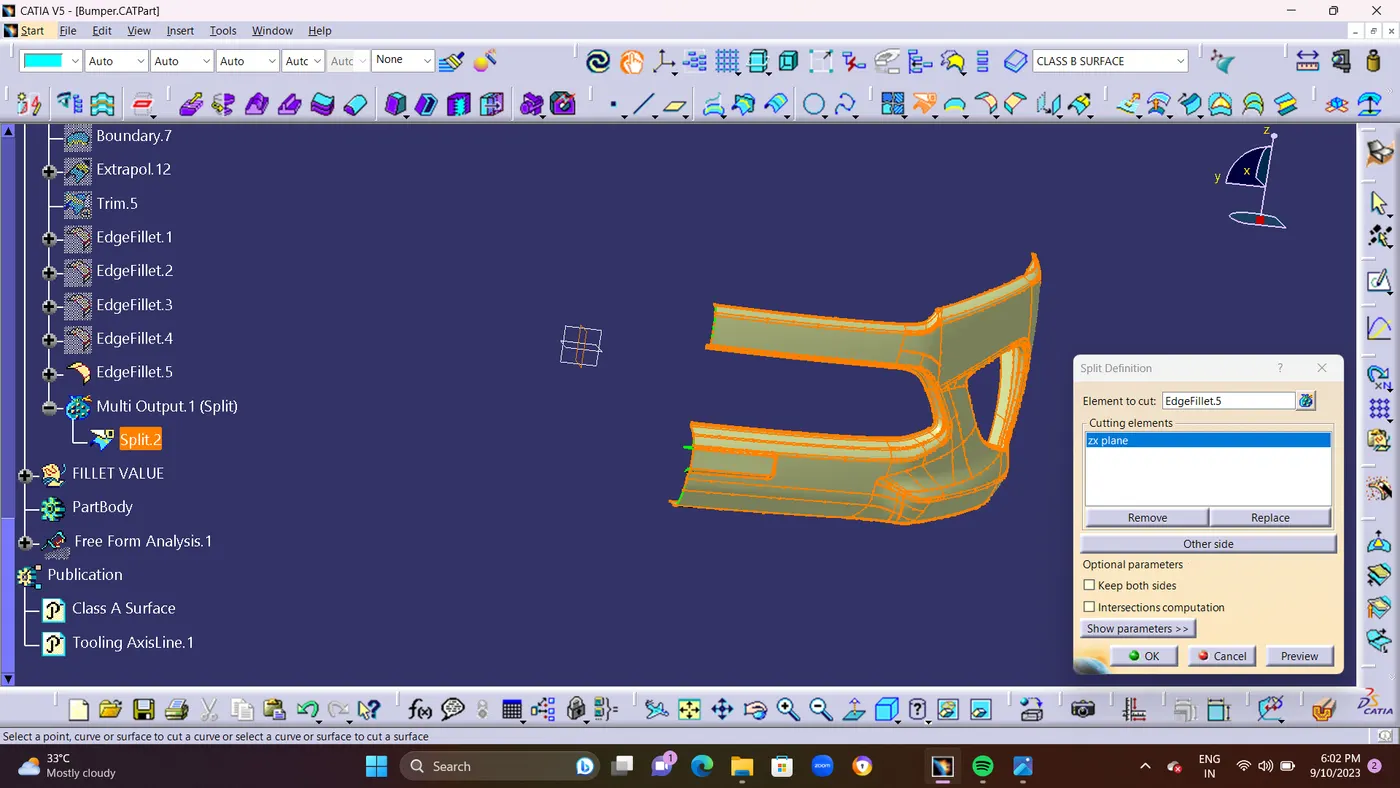
- Use SPLIT Command For Removing Extra Surface From Class B Surface.and Cutting Element as ZX Plane as shown in Below ScreenShot.and Finally Class B Surface as Been Created
- CLASS C SURFACE : Class C also known as the side wall of the surface, is a reference surface that the design engineer creates to connect Class A and Class B surfaces.
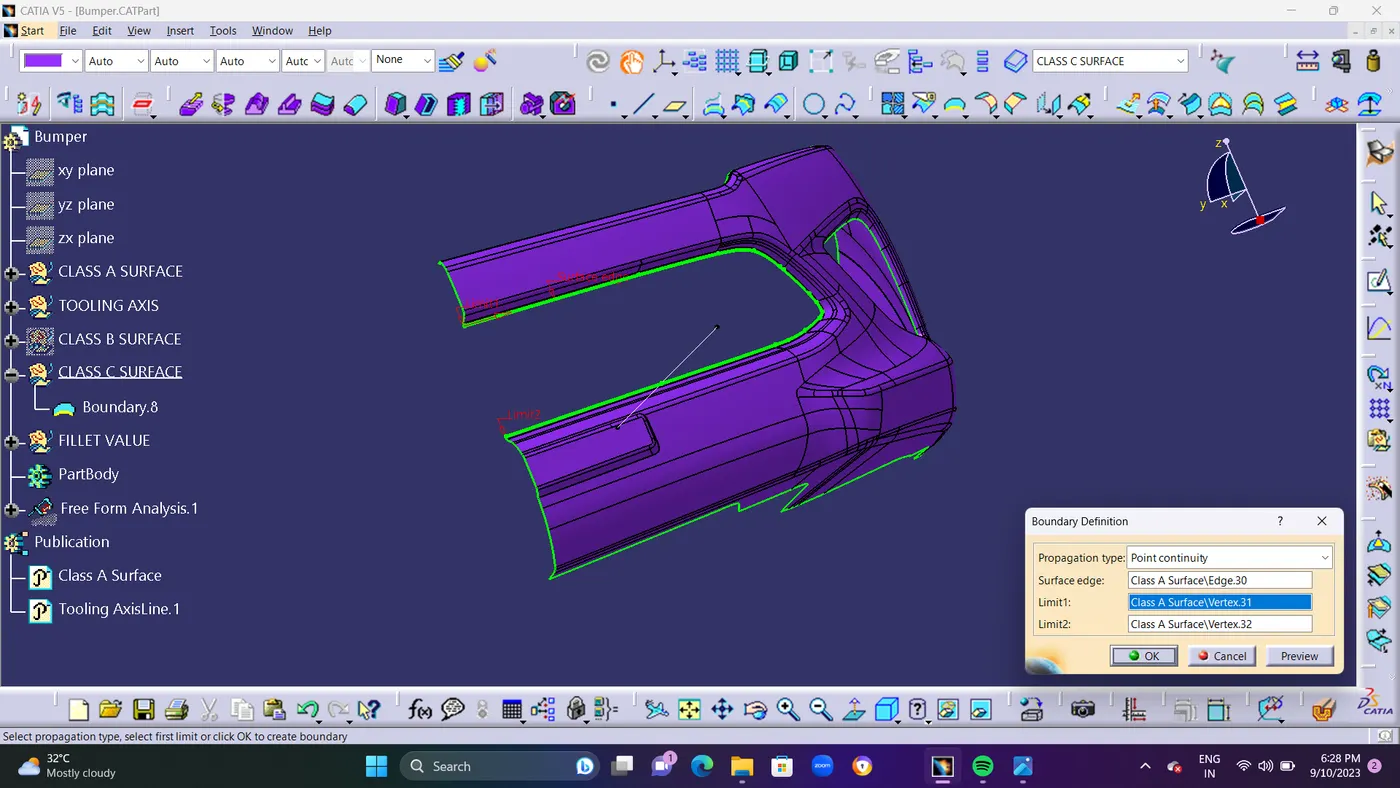
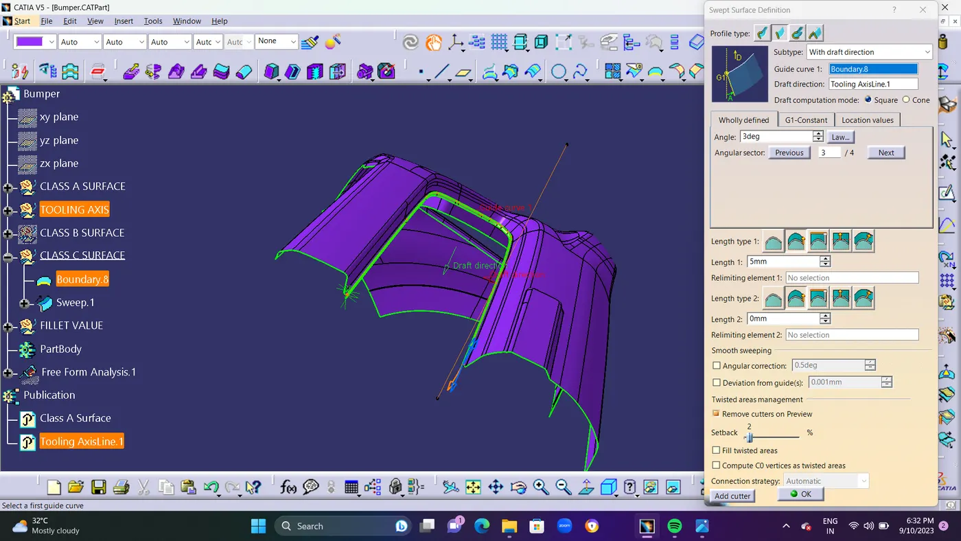
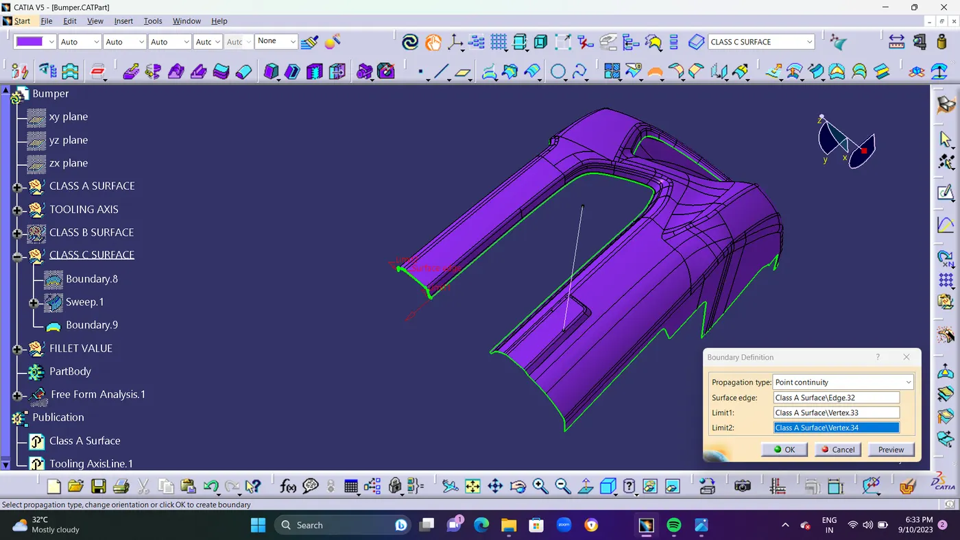
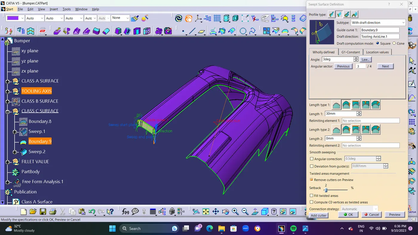
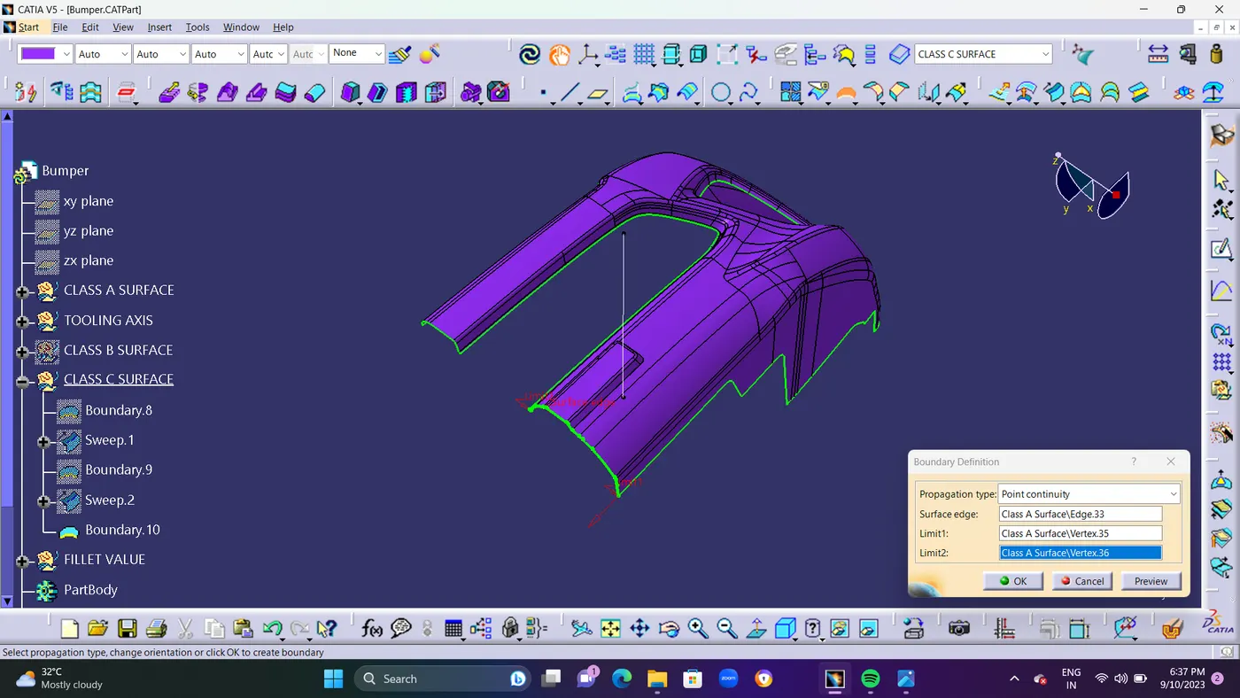
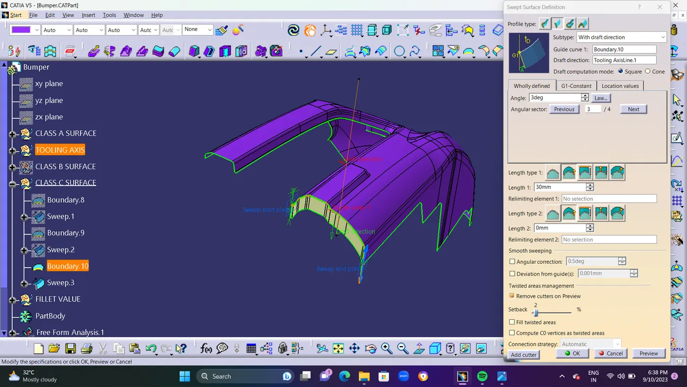
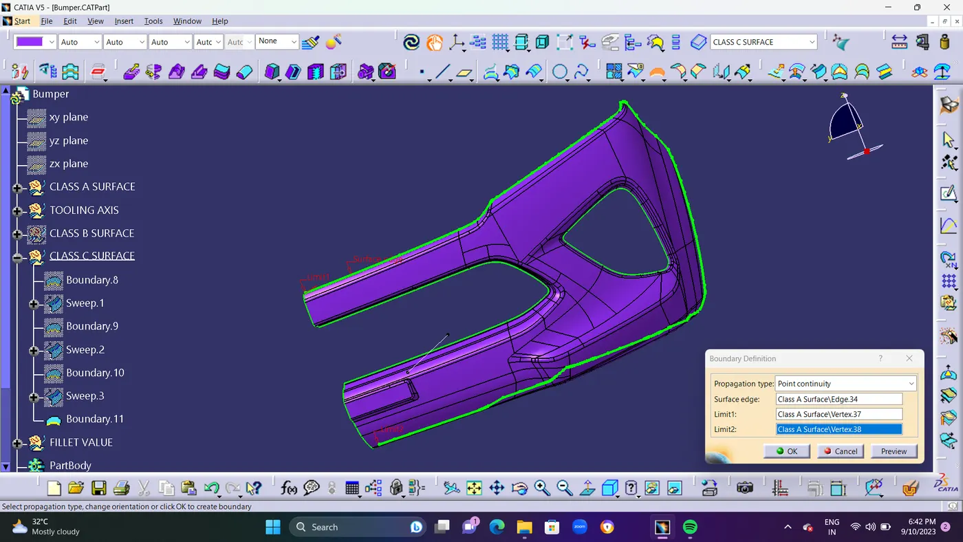
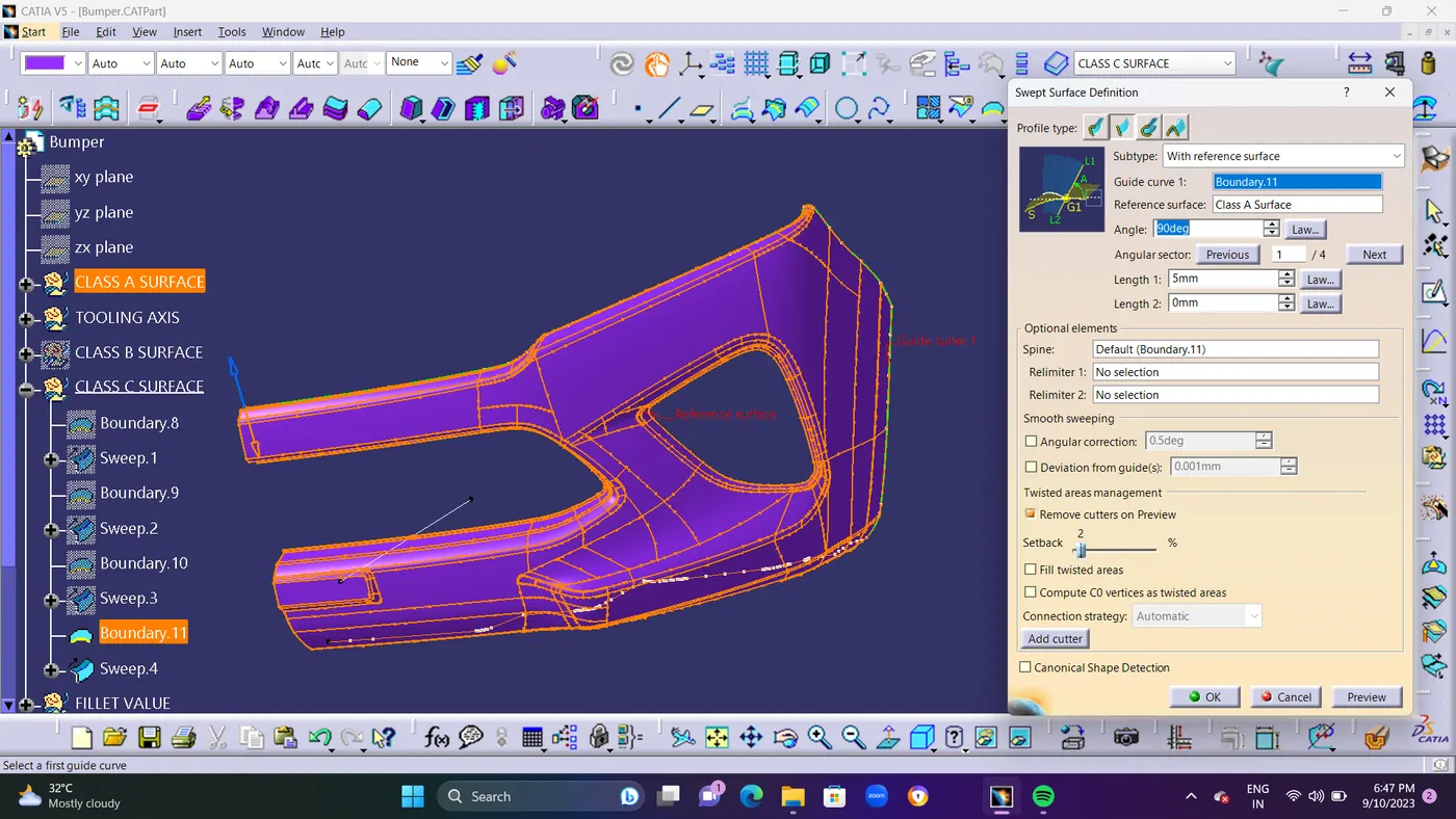
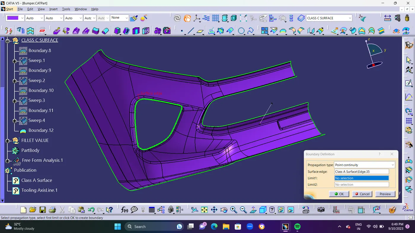
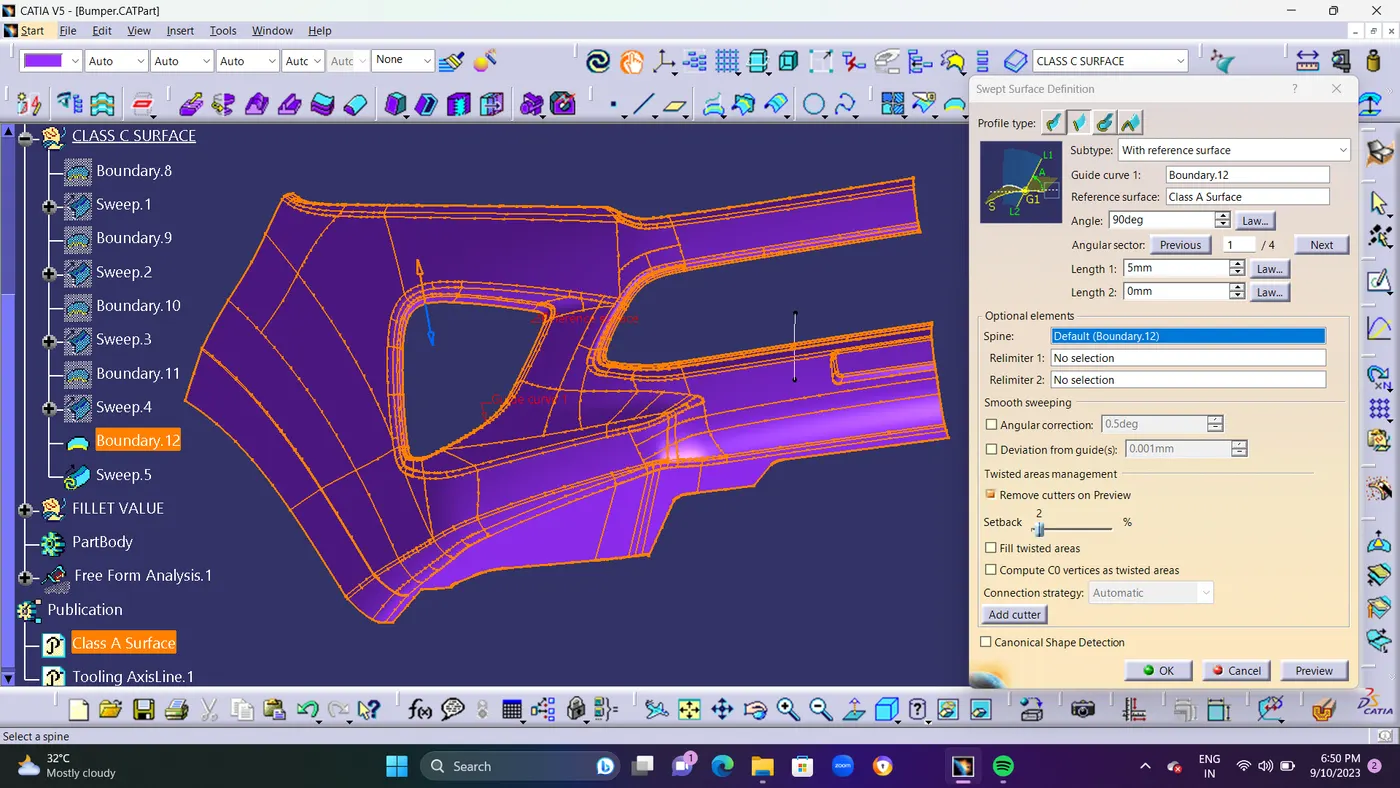
- STEP 7 : The boundary was developed by taking class A into account.To build a Class C surface, the sweep command was used for 3 DEGREE, and as a point of reference Line, the primary tooling axis and tooling direction were taken into account. Sweep Command is used to Extend the Border of Class A surface to Vertical direction for Creating Class C surface.
1.Boundary: pick the boundary for the next operation.
2.Swept: swept the selected boundary .
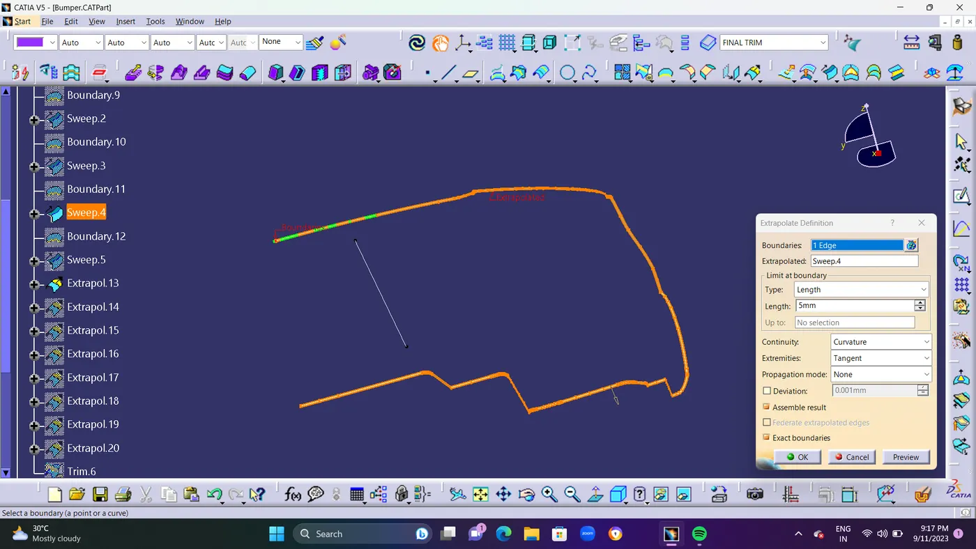
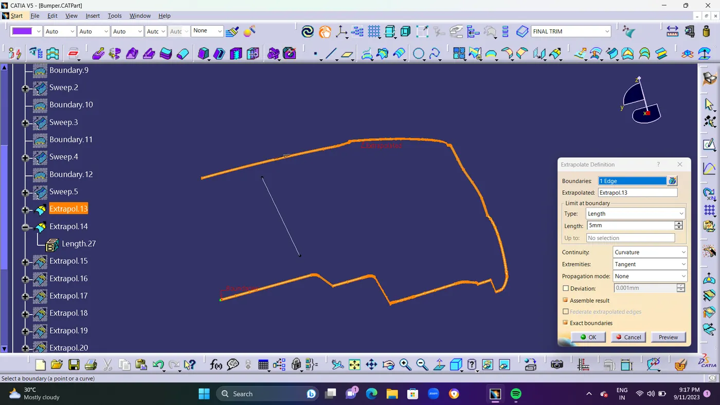
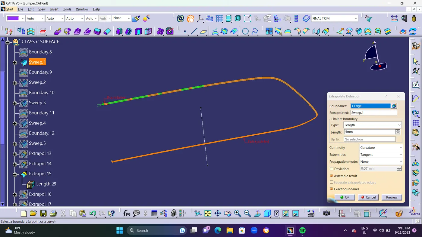
3.Extrapolate: surface can't join properly, so I used to extrapolate those surfaces.
4.Trim: trim those extrapolate surfaces and get a required surface.
5.Join: now join those surfaces with each other and form a single surface.
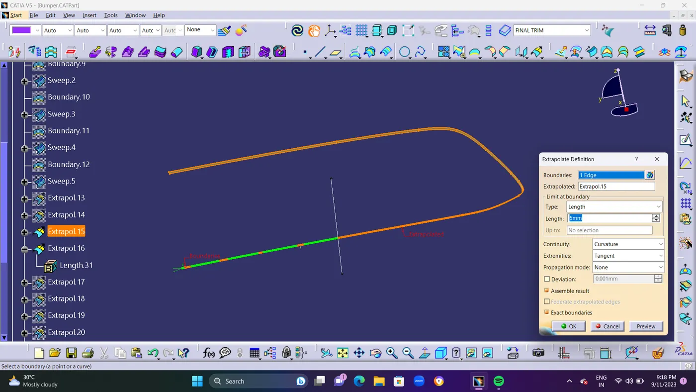
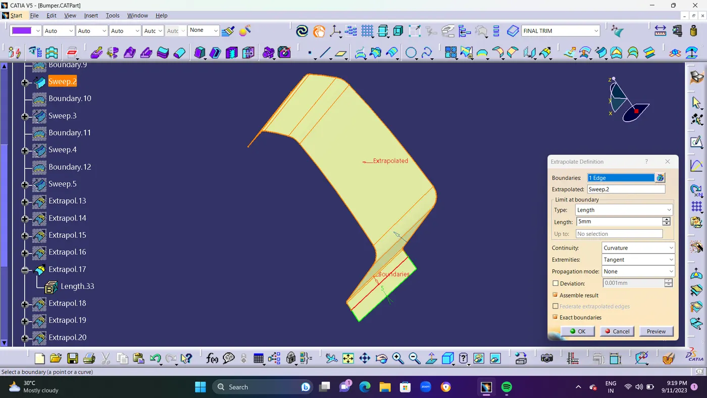
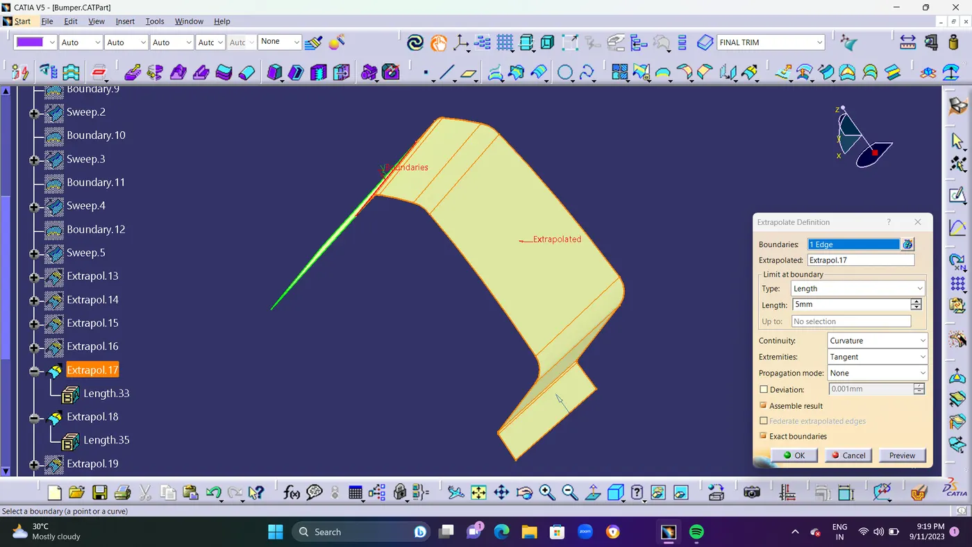
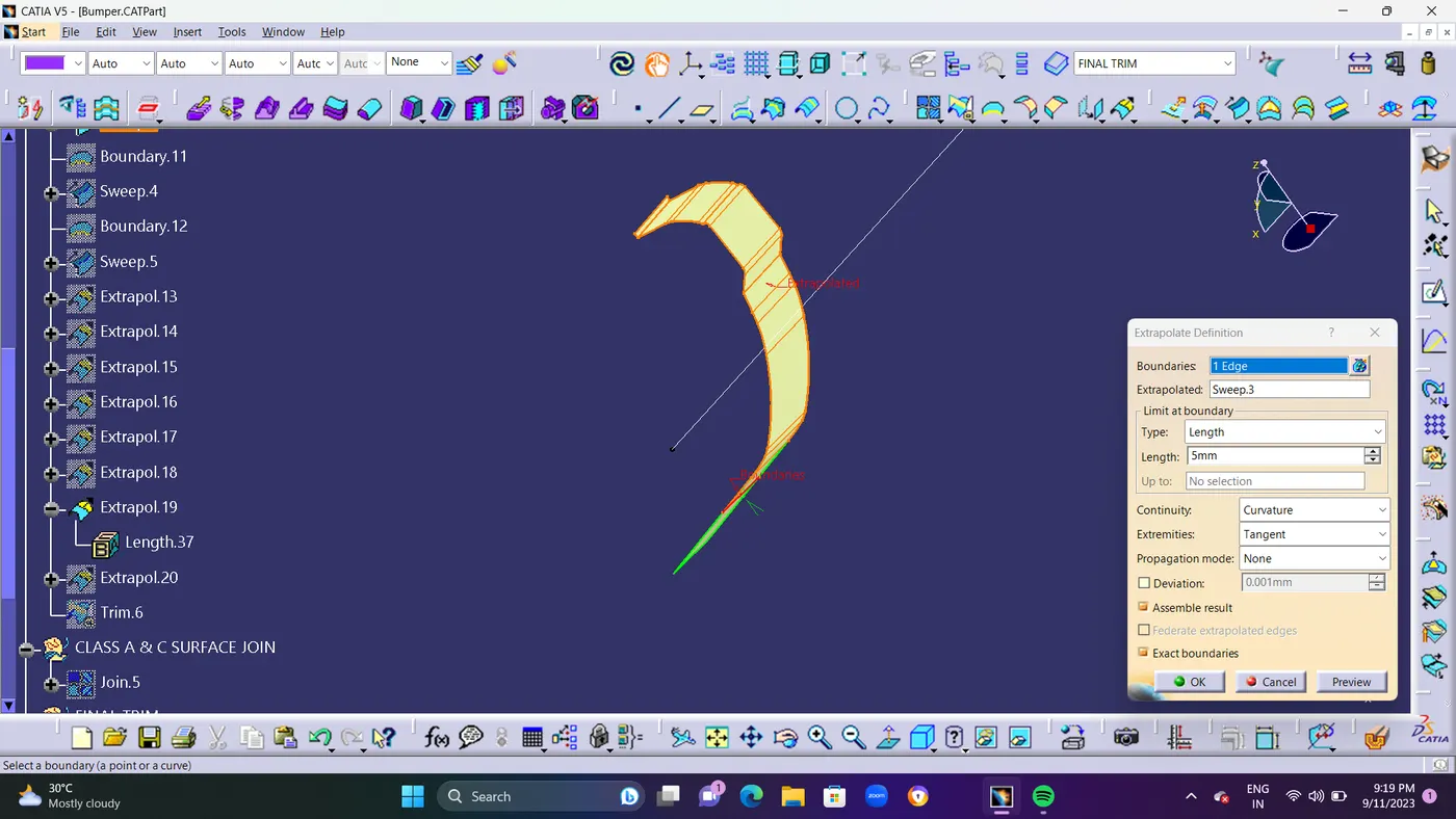
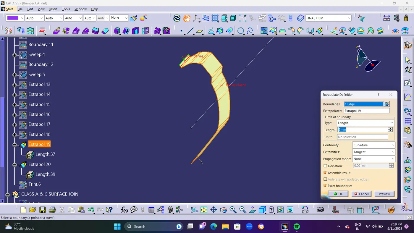
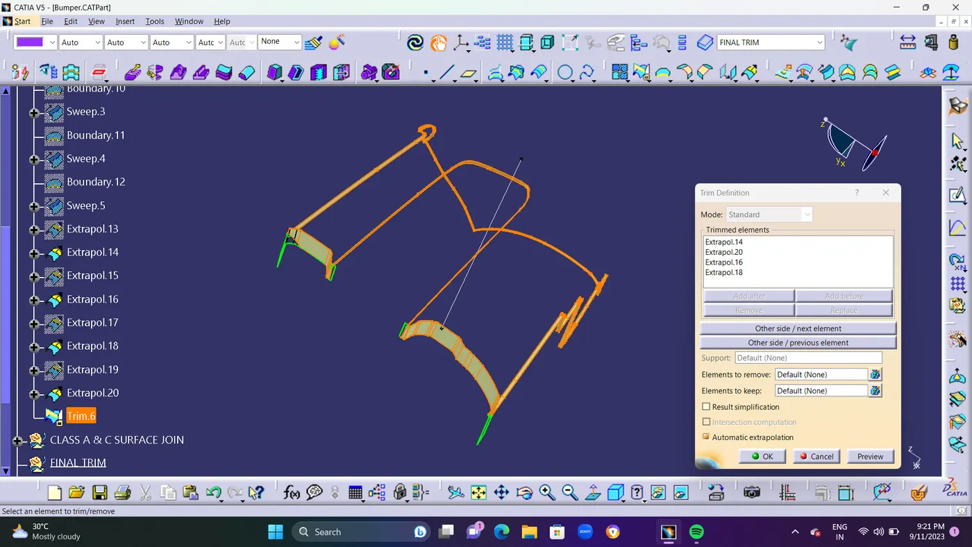
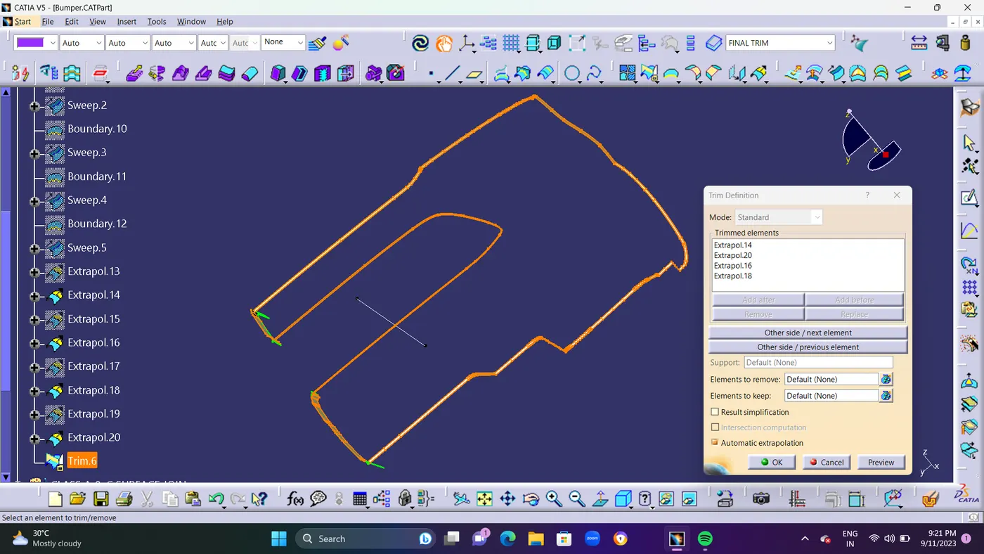
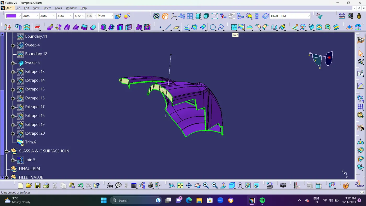
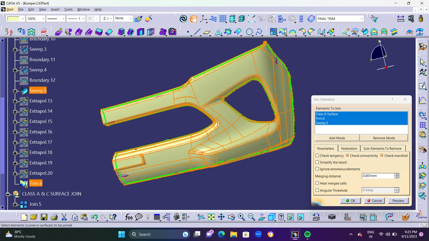
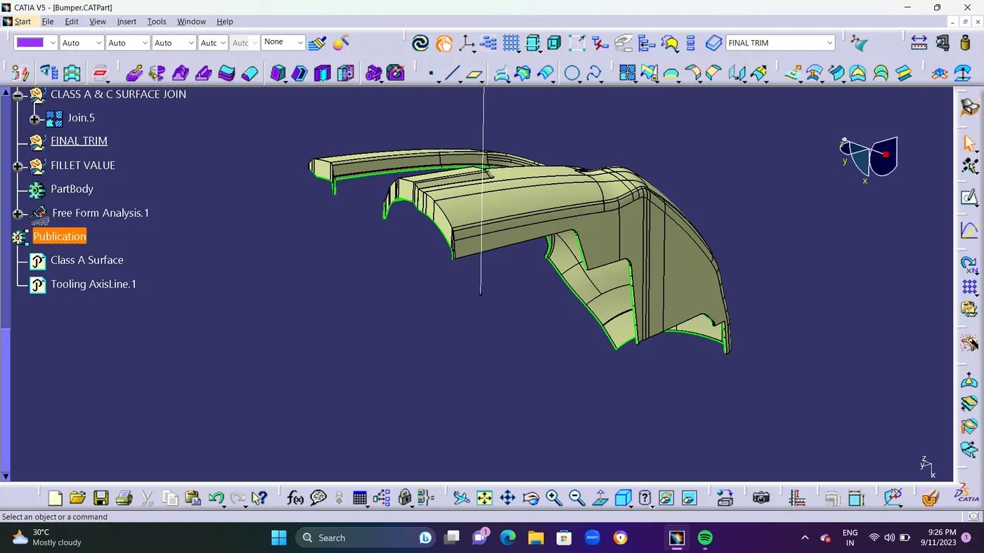
- STEP 8 : After Class C Surface As Been Created.Now We are going to Trim Class A and C Surface with Class B surface. While Trimming Its shows Some Error. Because in some area the Class B Surface Not Intersecting with Class C Surface.
- So Im Going take The Intersect command to Find where there are Gap and Area Not inersected in Class B surface with Class c surface.
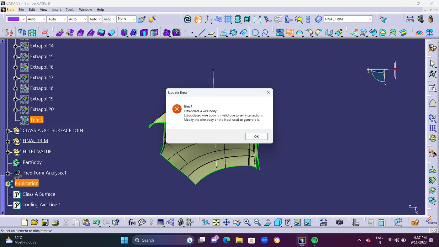
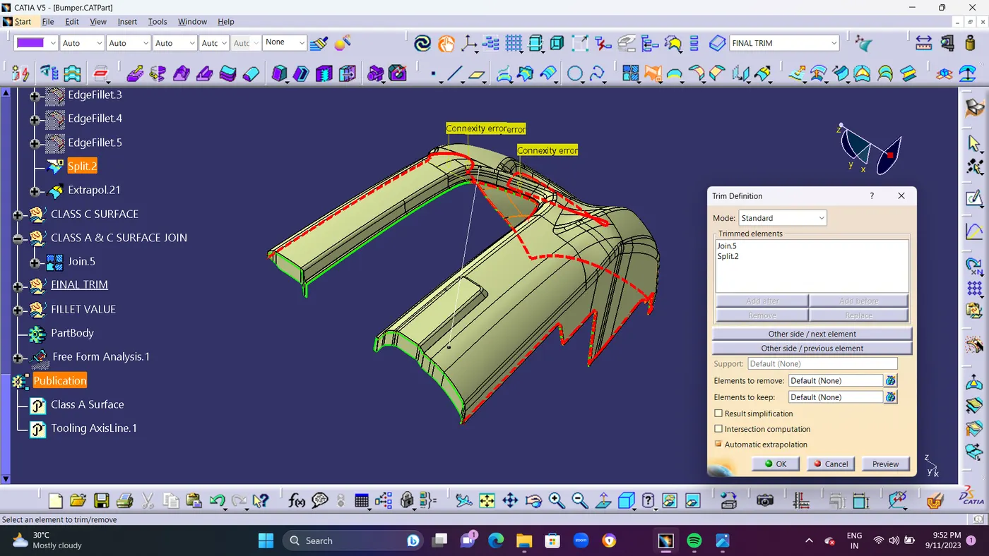
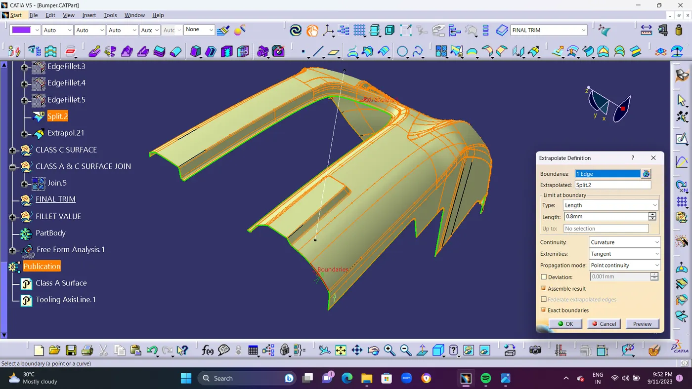
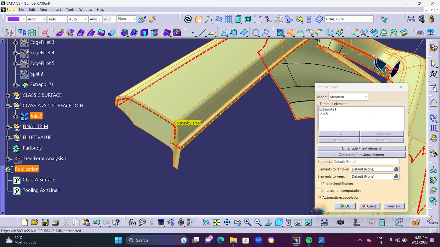
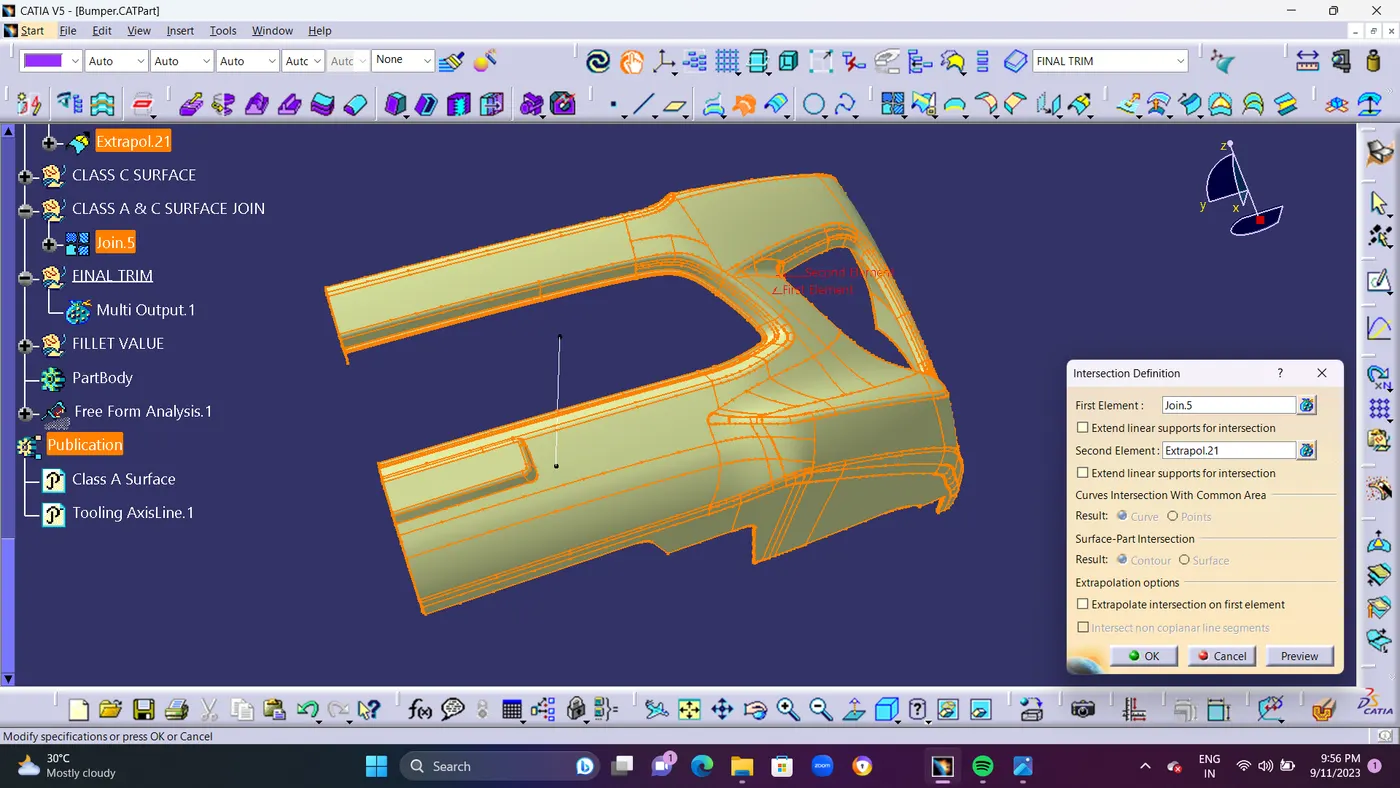
- Im Finding The Gaps in Between Class B Surface as Shown In Below ScreenShots
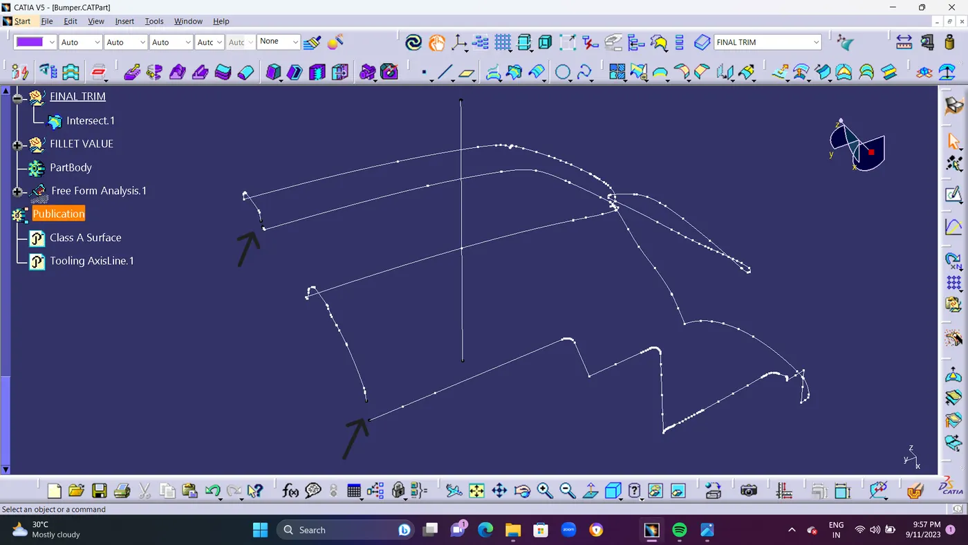
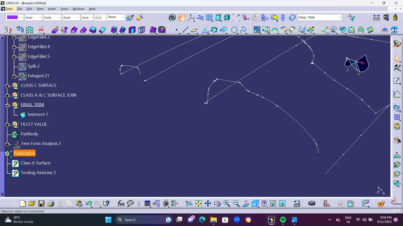
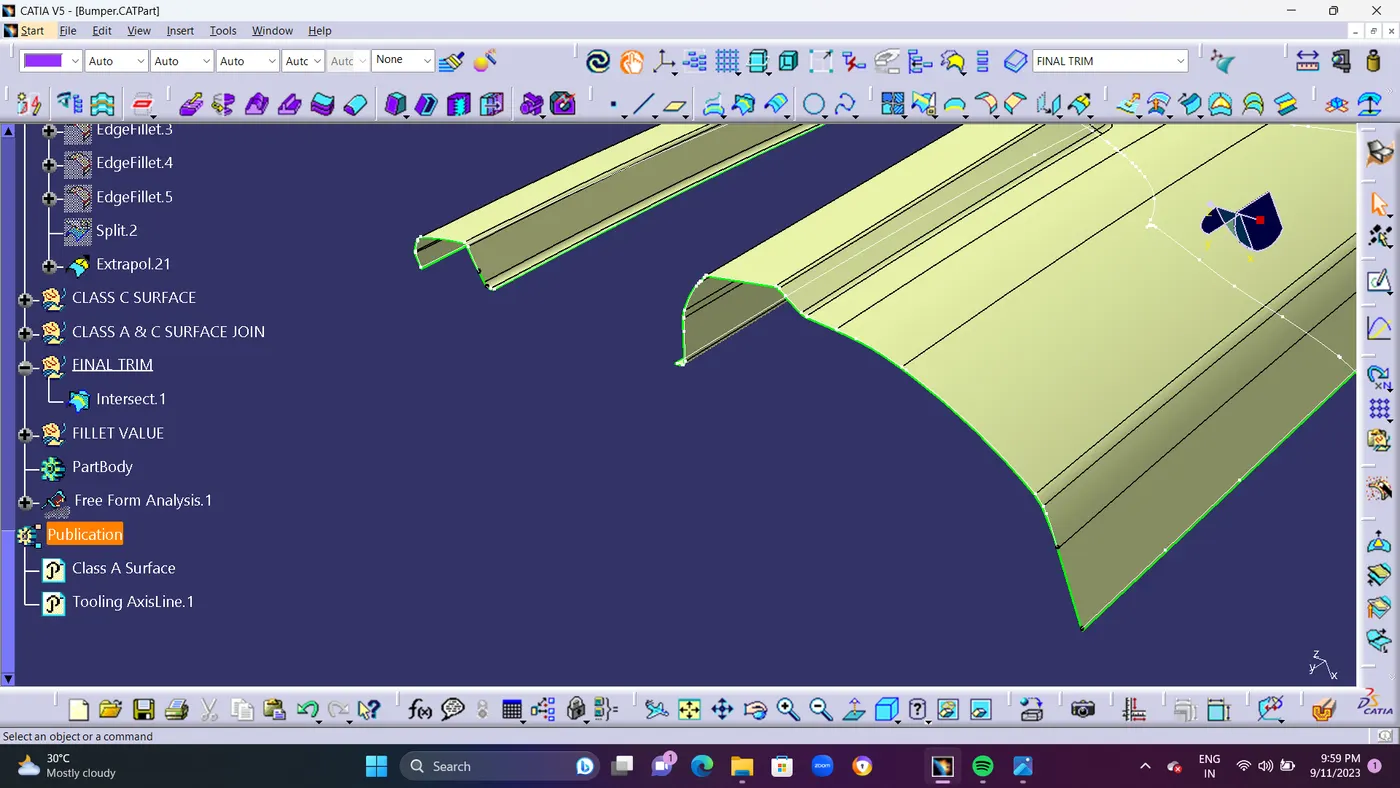
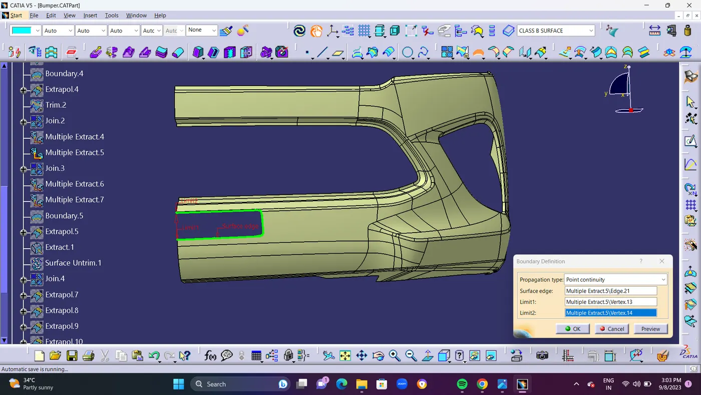
- STEP 9 : Use BOUNDARY Command to create a Boundary line where i want to Extrapolate my Class B Surface.
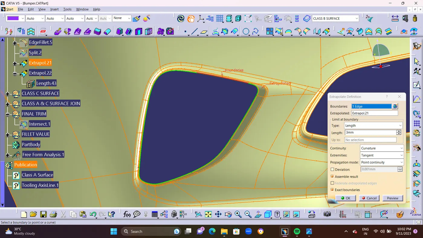
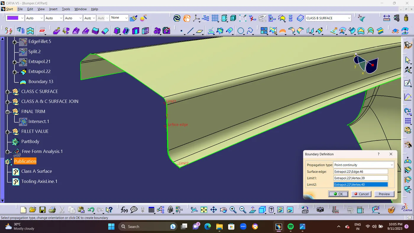
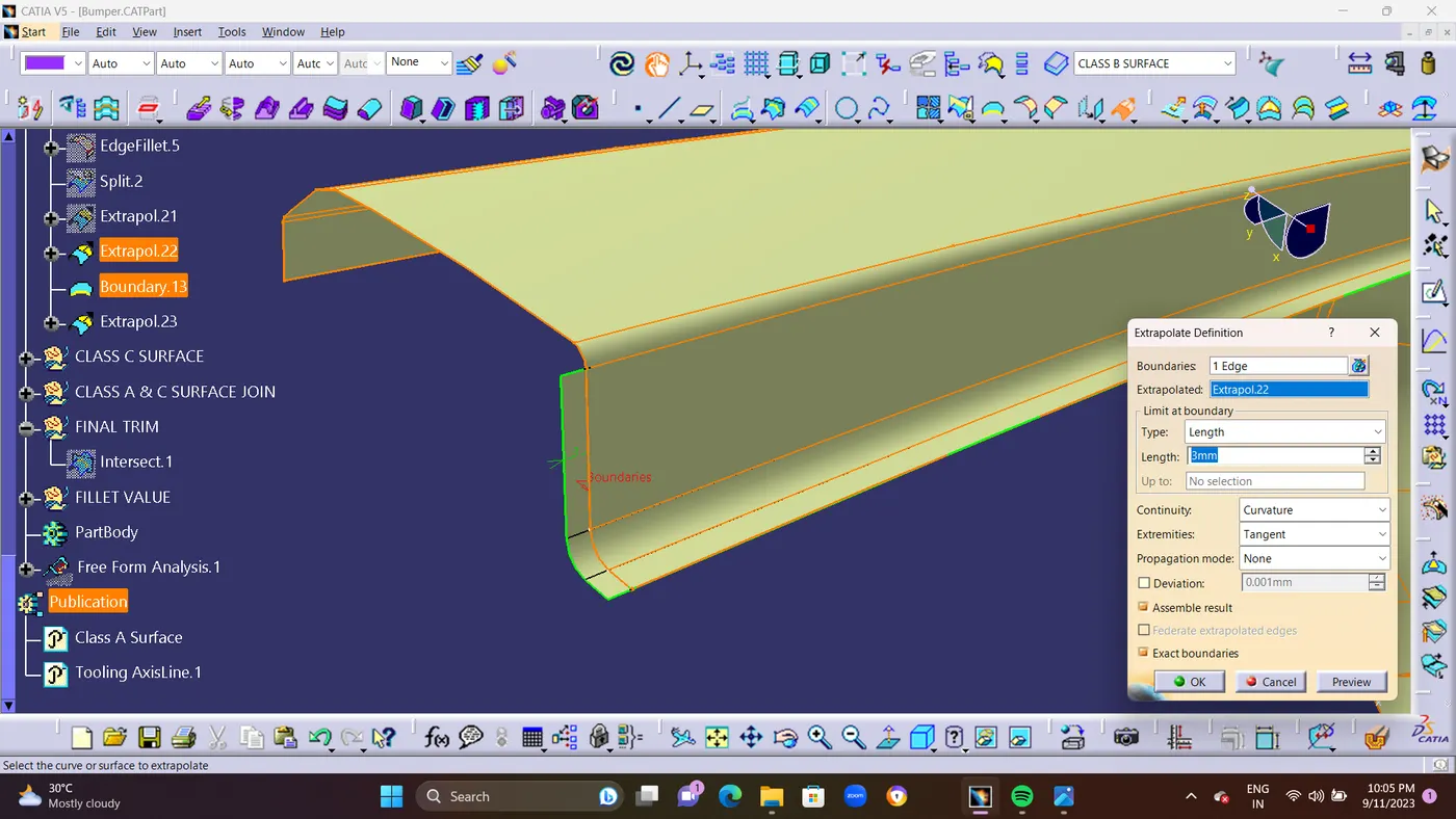
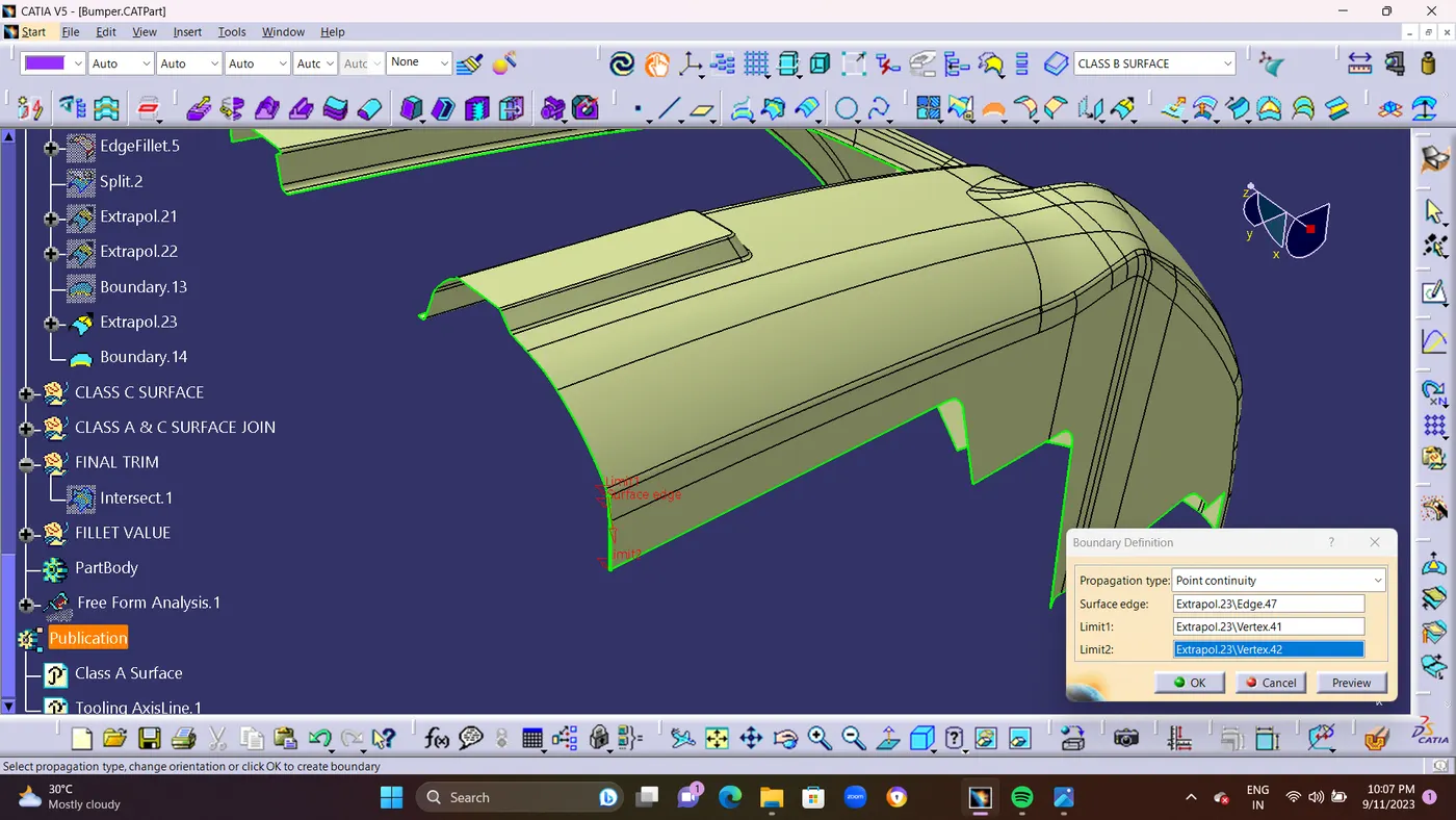
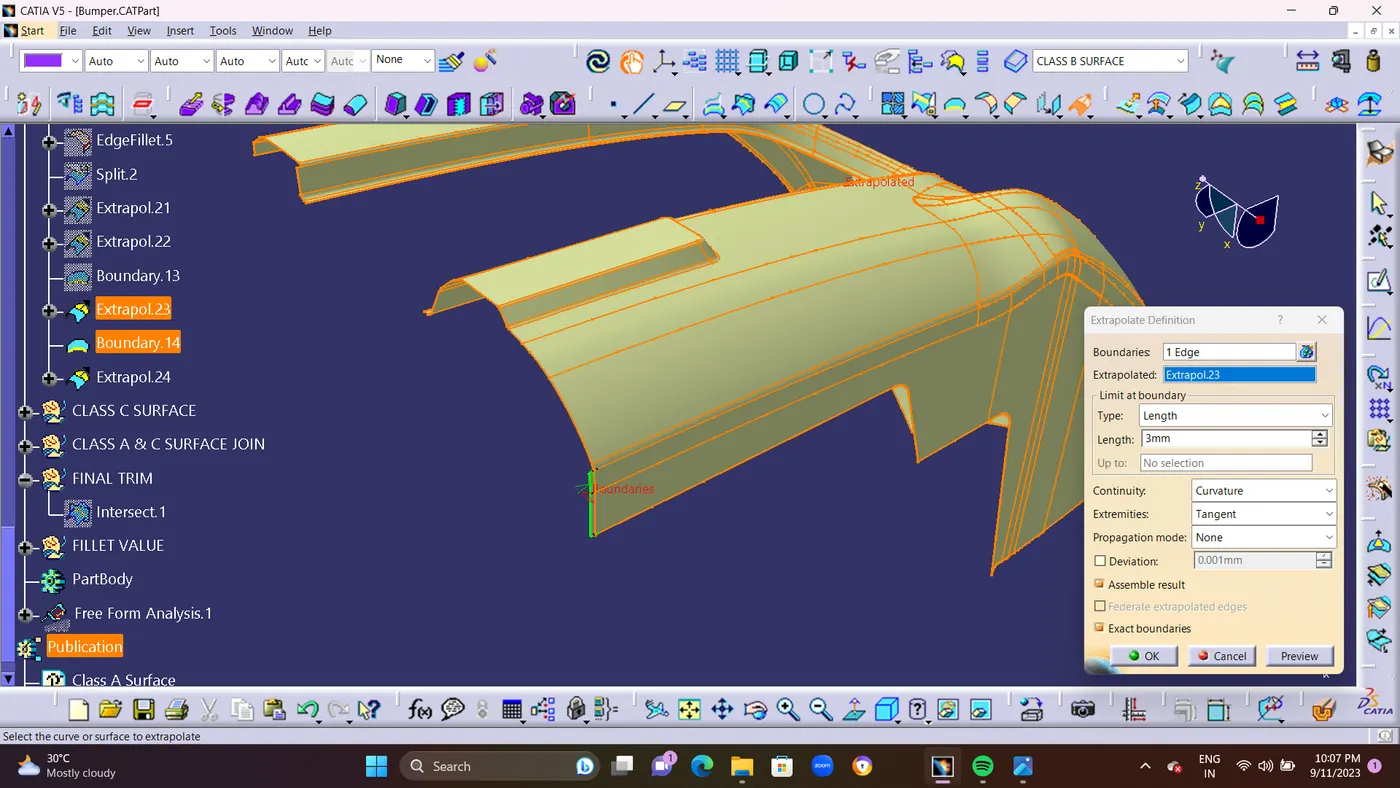
- and Finally I got the Closed Boundary or Intersect Line From Class B surface.as shown in below Screenshots.
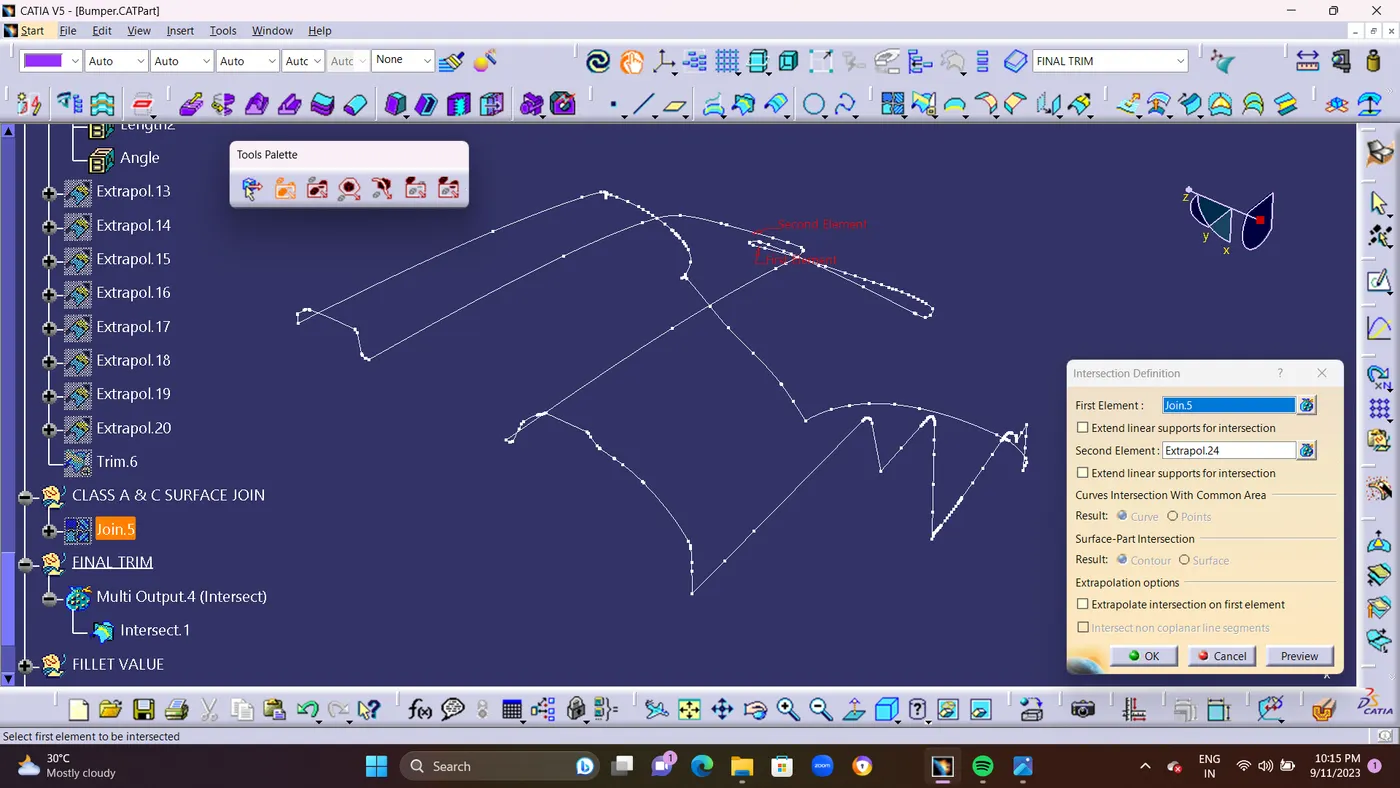
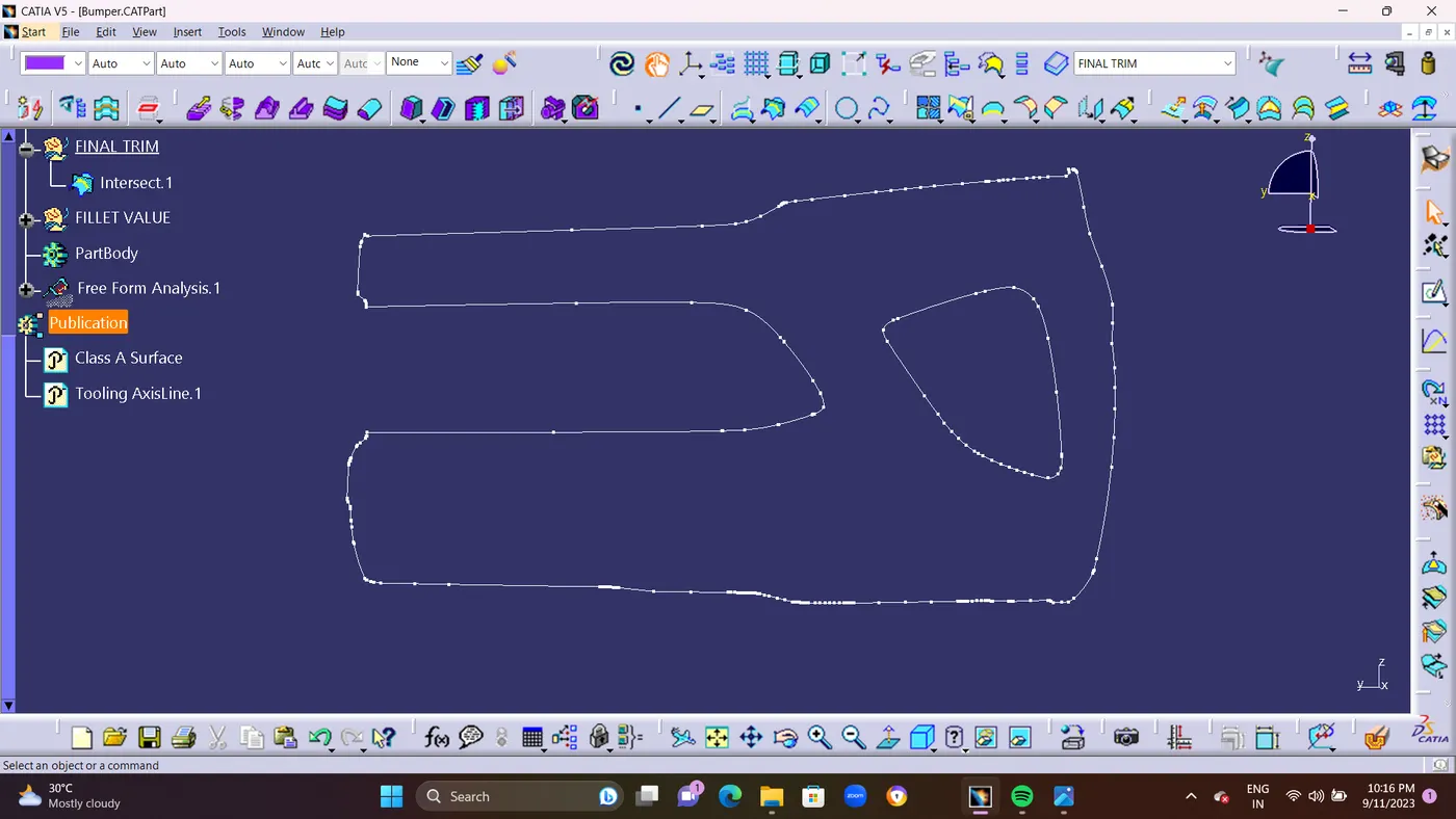
- STEP 10 : And use Final Trim for Trimming Class A and C Surface With Class B surface. Finally Surface as been created of 3mm gap between Class A and Class B Surface.
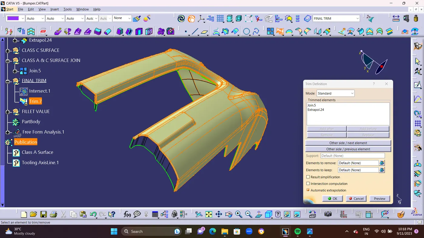
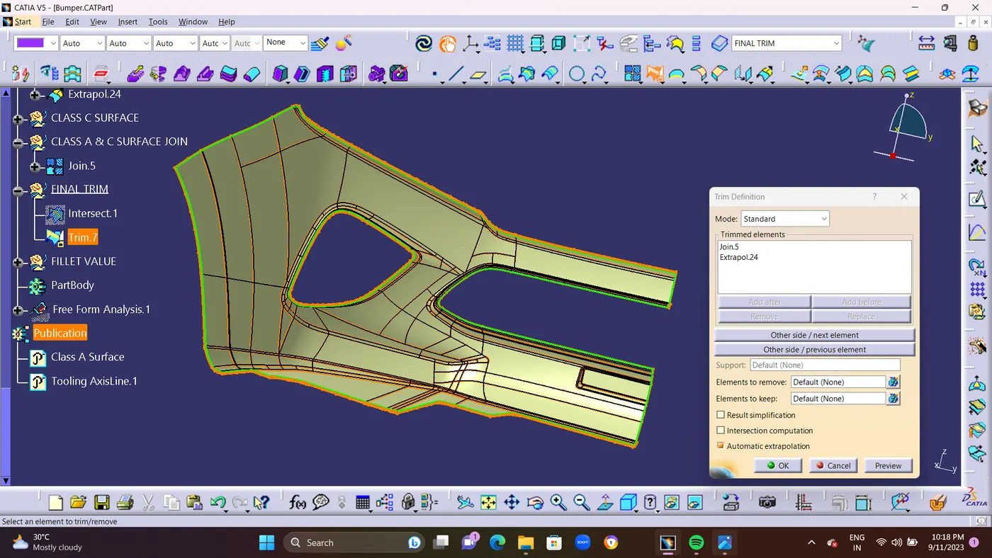
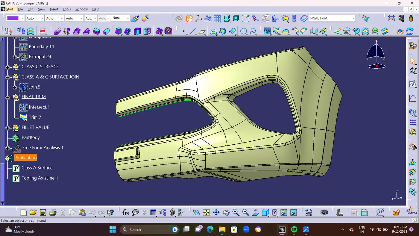
- STEP 11 : Check Finally There is No any Boundary in the BUMPER surface By using BOUNDARY COMMAND.if there is no any boundarys it shows Error and your work is clear. if you find any Boundary line its seems you done ah mistake or wrong surface while joining.so read do it.
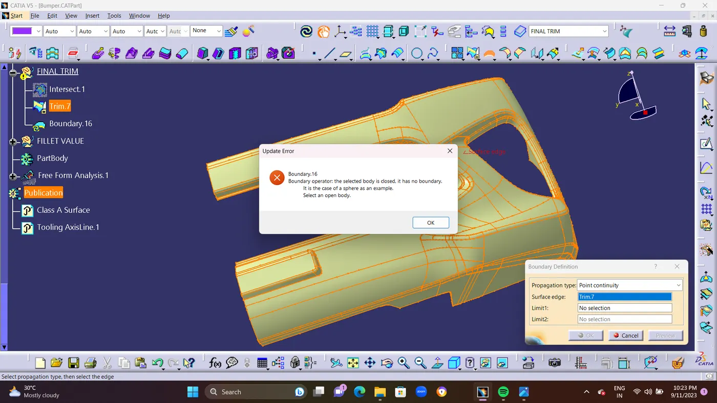
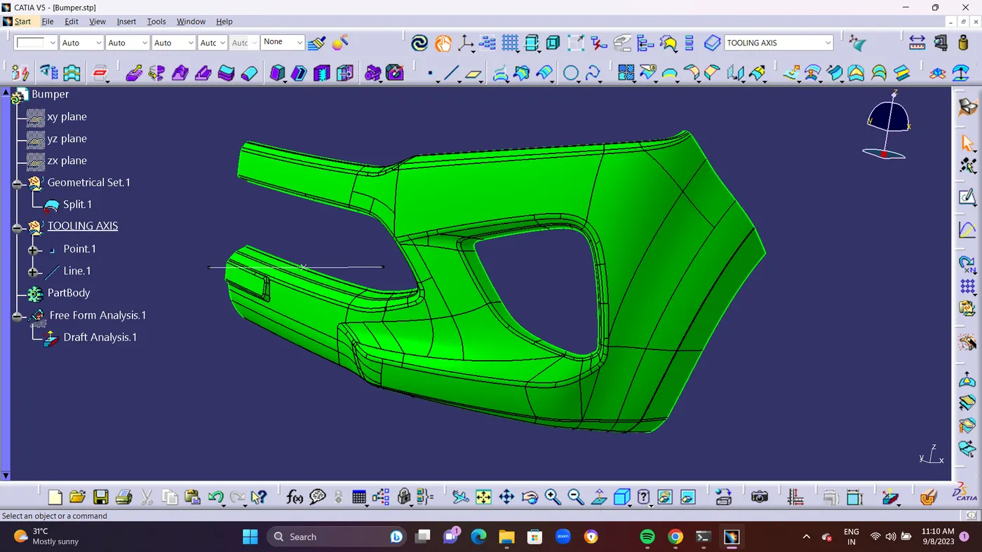
- STEP 12 : And Finally Created Close Surface in PartBody By Using CLOSE SURFACE METHOD.Using TRIM.7
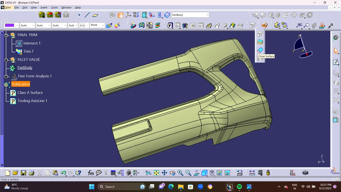
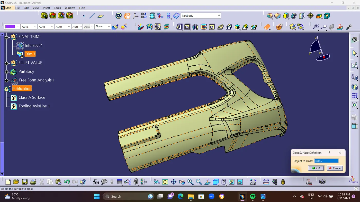
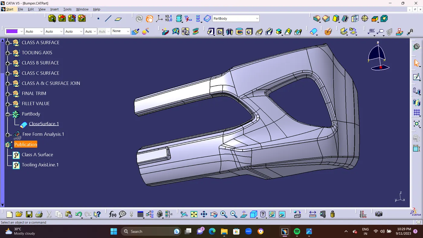
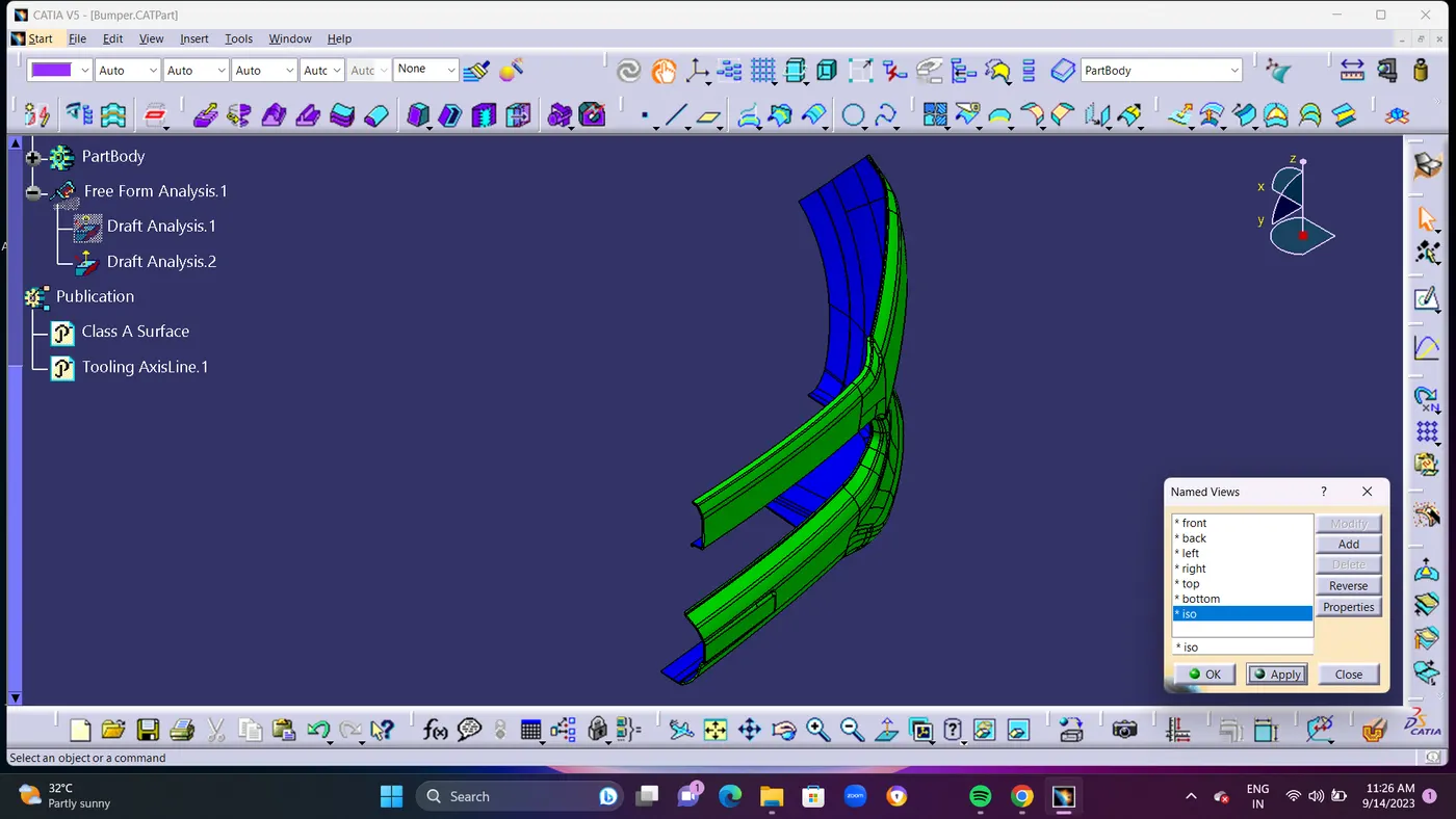
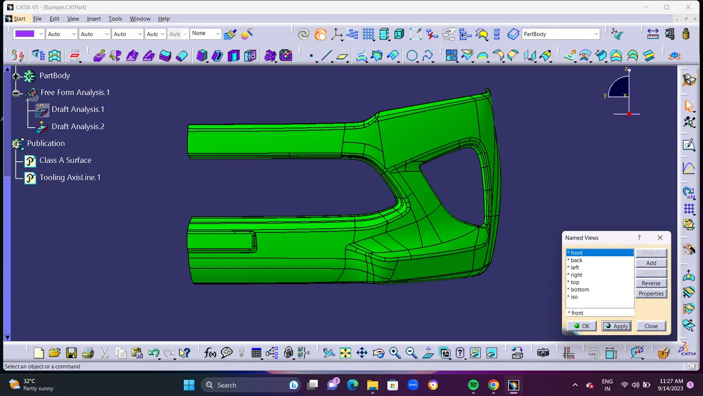
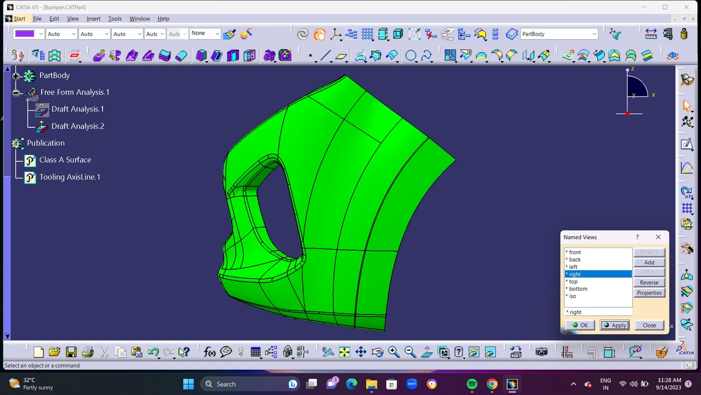
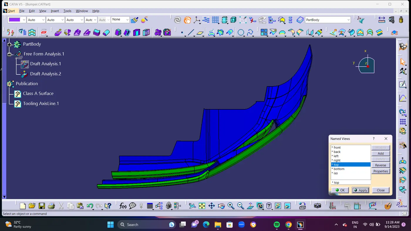
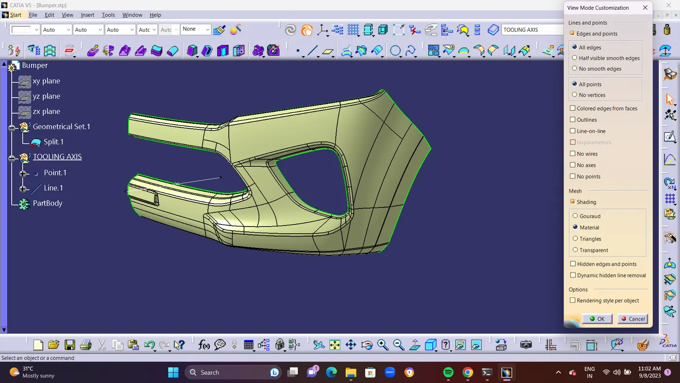
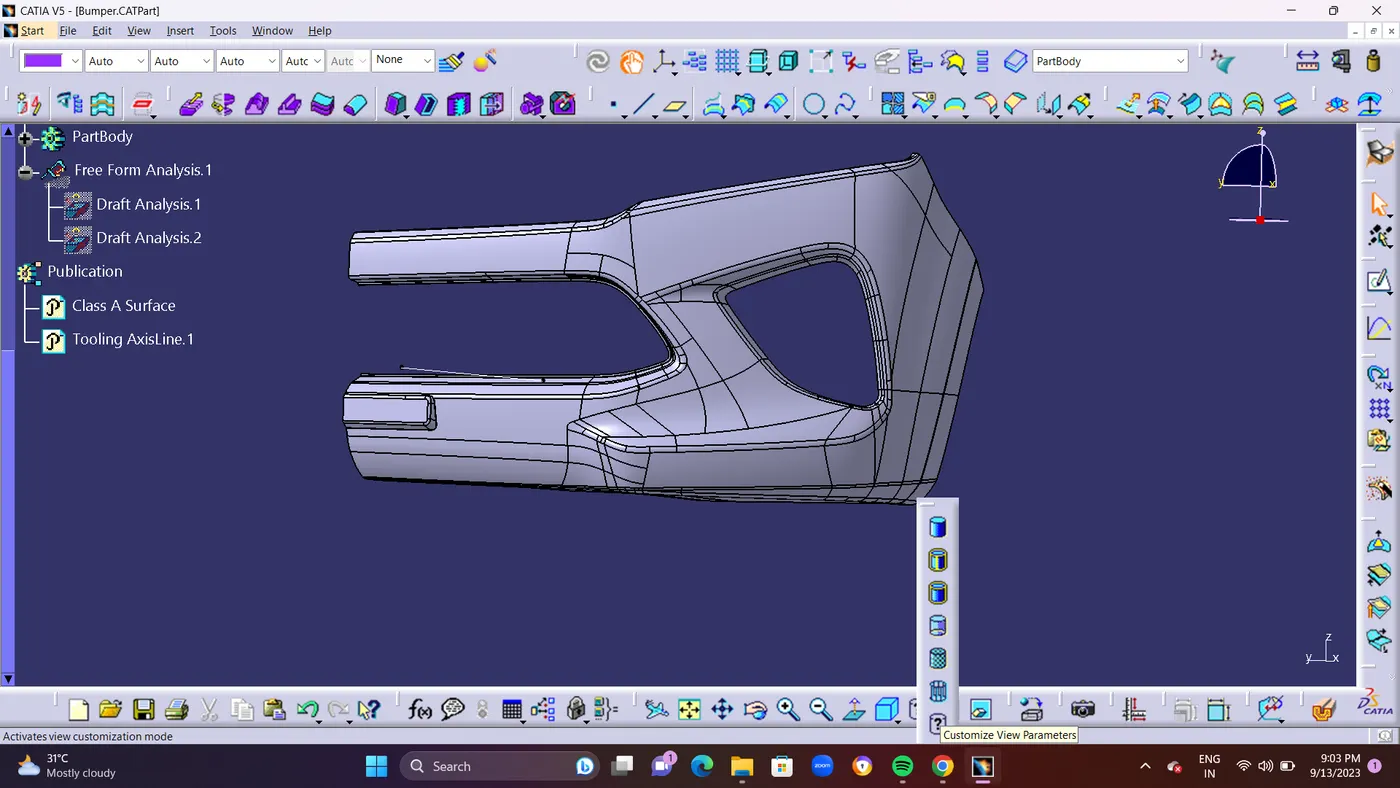
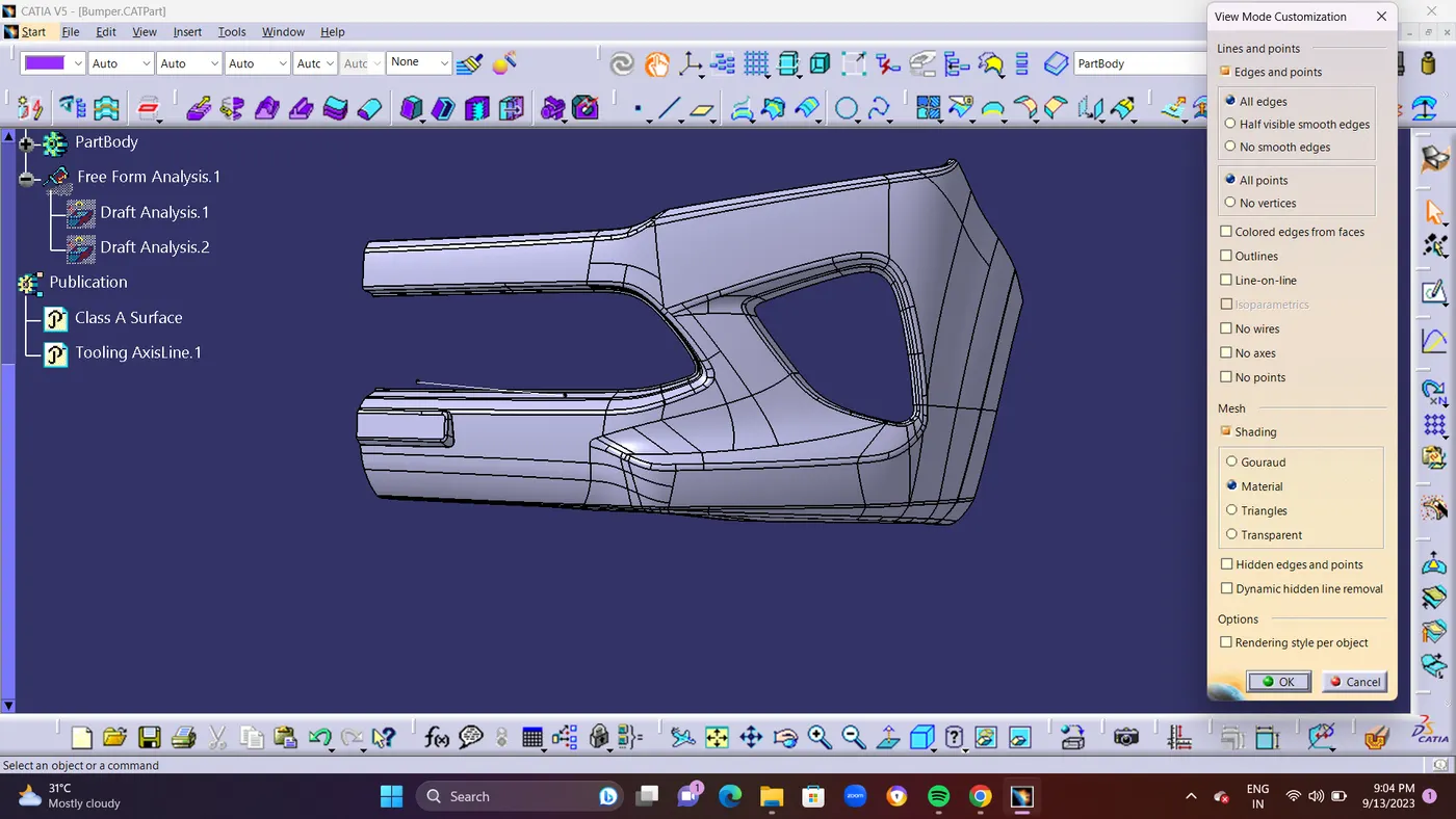
- STEP 13 : After Creating CLOSE SURFACE DRAFT ANALYSIS METHOD is used for Class A surface and Closed Surface.Draft analysis is required to check if a part has required draft or not. Draft is required so that a part can be ejected from its mould easily.Draft will be Maximum 3 Degree.But For me its failing at 2.9 Deg So i used to make it as 2.5 Deg As Maximum Level in Closed Surface Draft Analysis Method and it is passing at 2.5 Deg.Make Sure you are in MATERIAL MODE To Check Draft Analysis.Use Compass in Tooling AXIS while Drafting.
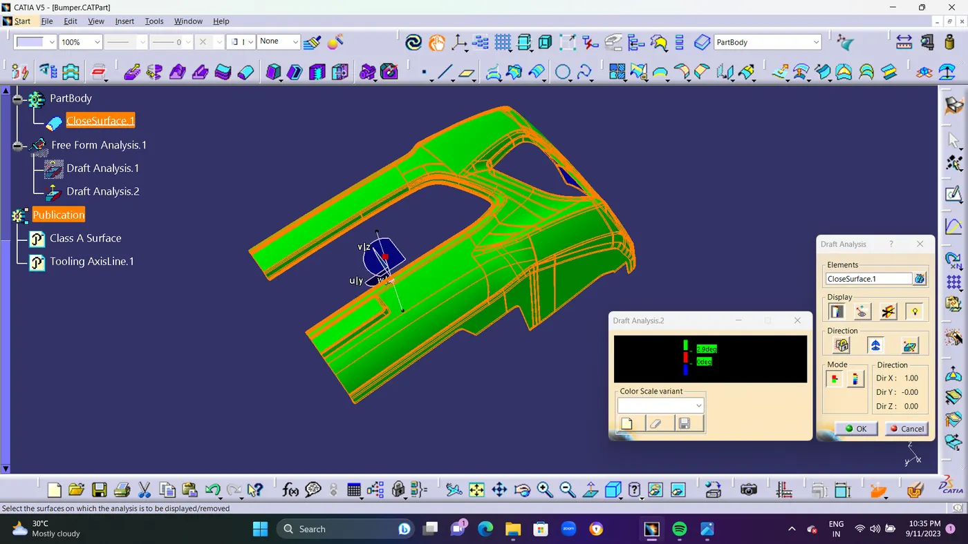
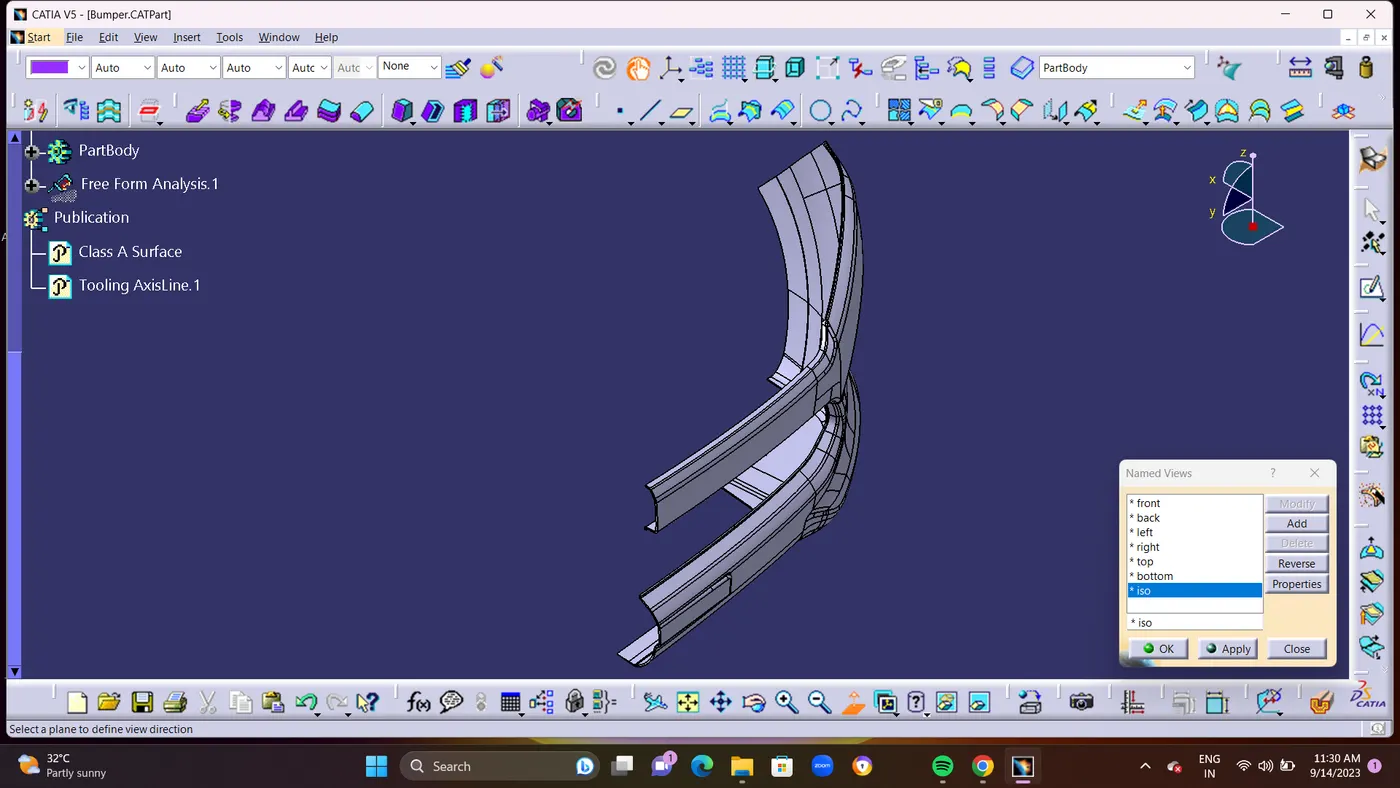
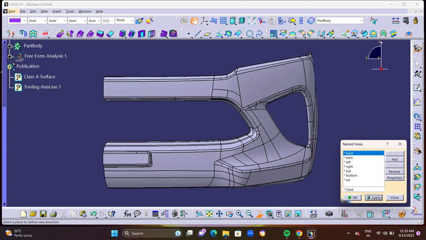
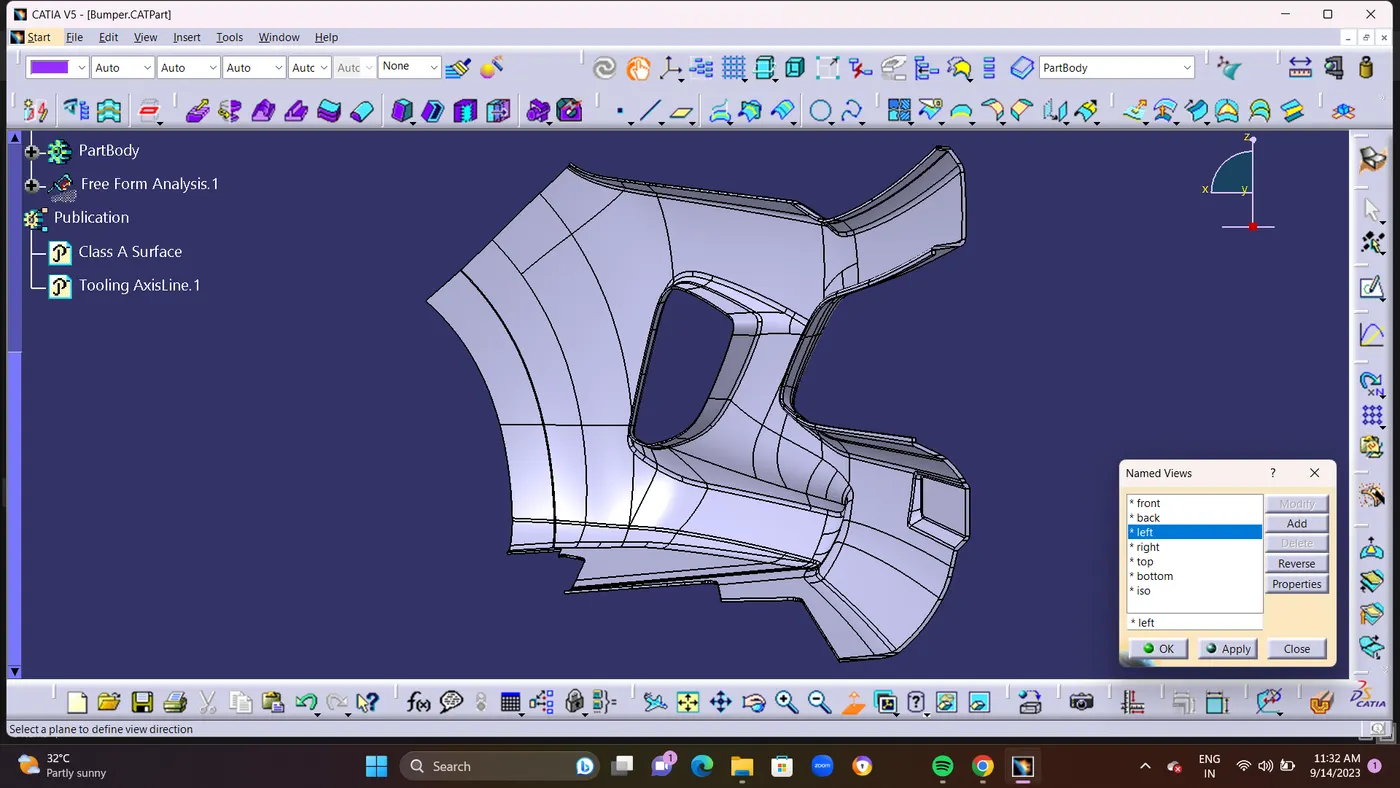
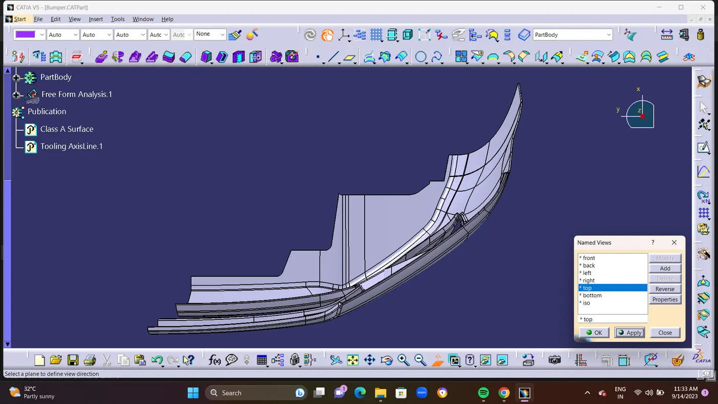
- STEP 14 : In Draft Analysis If it shows Green Colour Surface. its Pass in Drafting.Suppose its shows in Red Colour Surface its Fails in Draft Analysis.and Finally ISO,FRONT,SIDE, and TOP View Should Be taken As ScreeenShots.
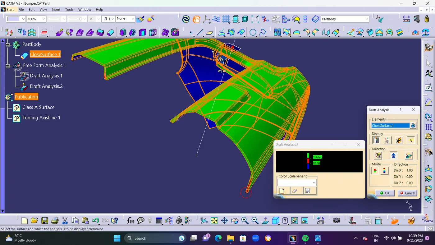
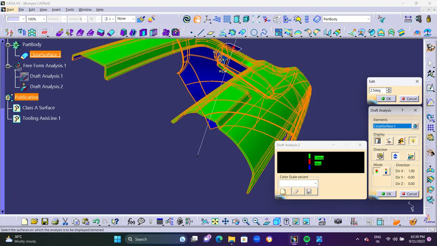
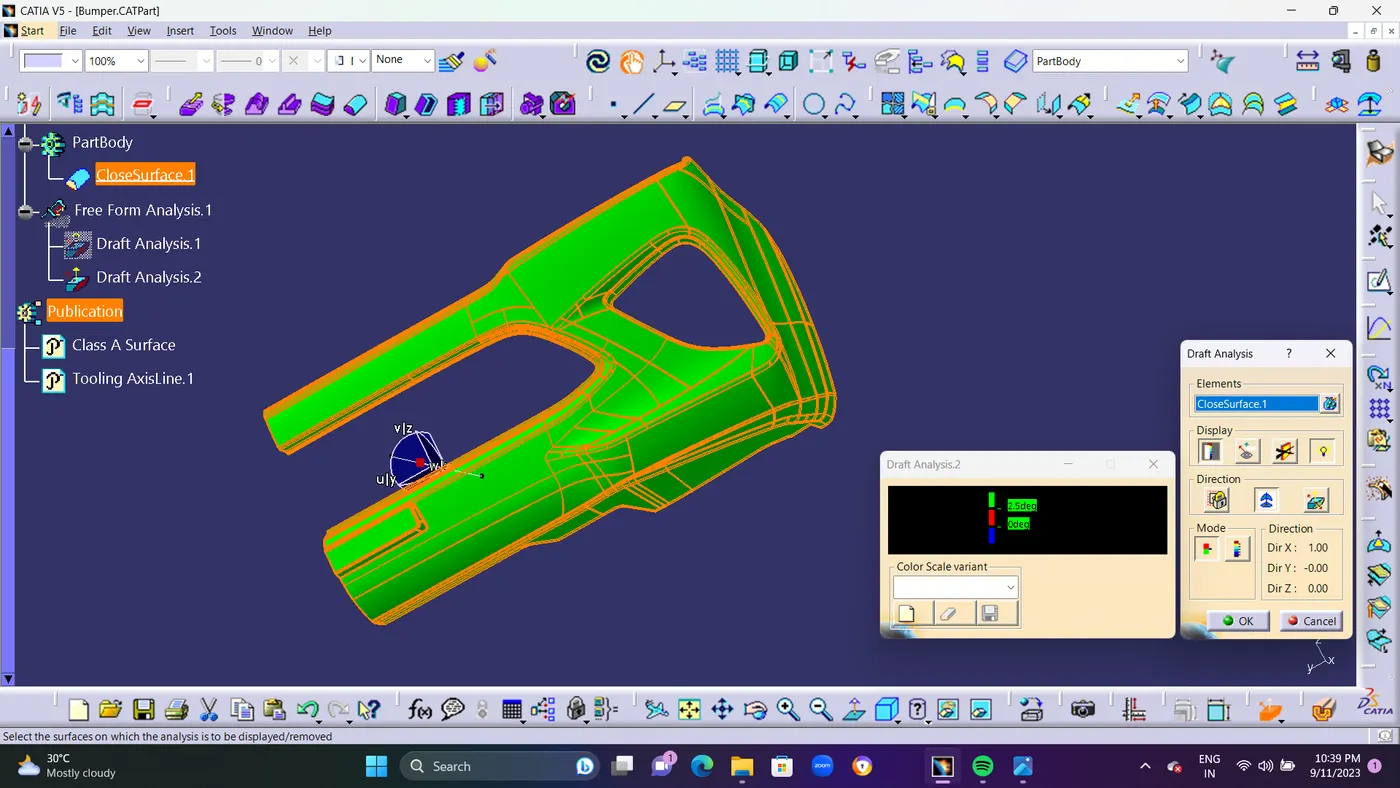
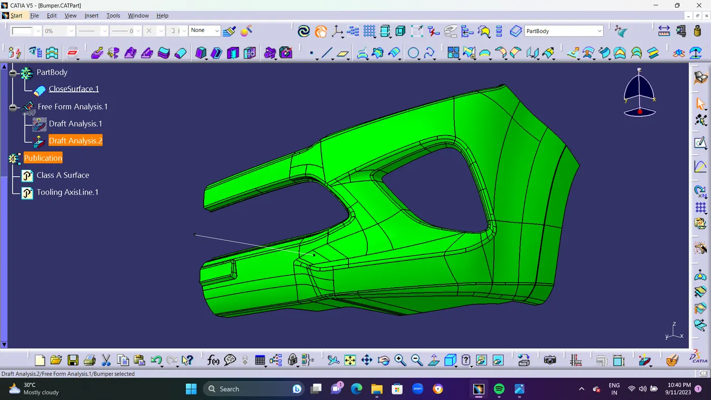
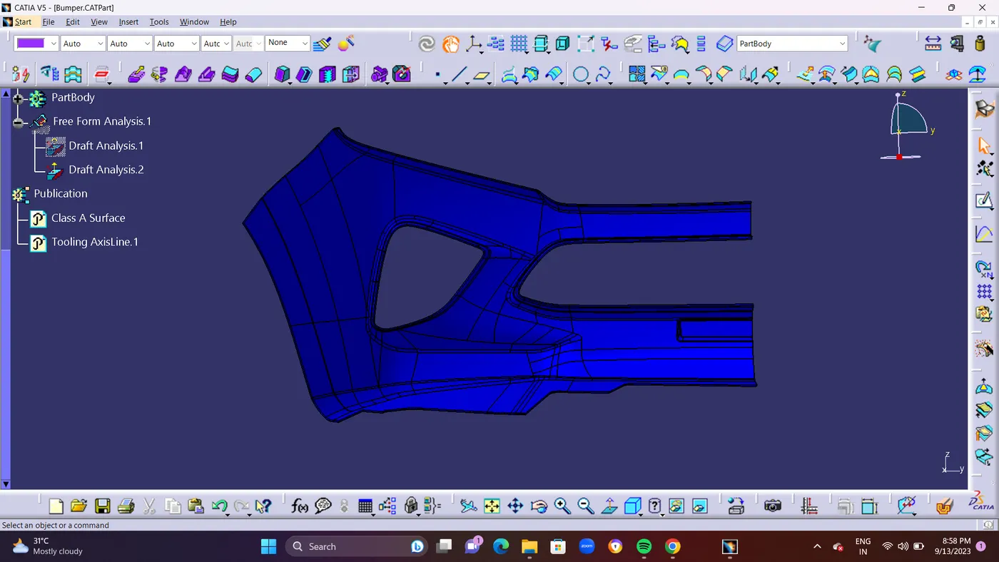
- STEP 15 : Finally take an Screen shots of ISO,FRONT,SIDE,&TOP View of Draft Analysis and Part Body in Closed Surface.